

Page 1

Version
3
VCA-5
Installation Guide
Cloud Electronics Limited
140 Staniforth Road, Sheffield, S9 3HF England
Tel +44 (0) 114 244 7051
Fax +44 (0) 114 242 5462
E-mail
Web site http://www.cloud.co.uk
info@cloud.co.uk
Page 2
VCA-5:
Installation Guide 1
VCA-5
Installation Guide
1 Introduction
The VCA-5 is an optional module that fits inside the
CX-A450 and CX-A850 to allow remote level control. The
CX-A450 can accommodate up to four VCA-5 modules the
CX-A850 can accommodate up to eight, one module for
each channel.
2 Installation Information
The VCA-5 is supplied with an M3 screw, 35mm M3 hex spacer and a 3-pin screw terminal plug.
The modules plug into connectors on the input PCB towards the rear of the amplifier. The
connectors are clearly marked as ‘CON X’ where ‘X’ is the channel number between 1 and 8 (see
diagram and list below): -
CON1 = Channel 1
= Channel 2
CON2
CON3 = Channel 3
CON4 = Channel 4
CON5 = Channel 5 (CX-A850 only)
CON6 = Channel 6 (CX-A850 only)
CON7 = Channel 7 (CX-A850 only)
CON8 = Channel 8 (CX-A850 only)
3 Installation Instructions
1. Turn the power off and remove mains cable.
2. Remove the top panel
3. Locate required PCB mounted VCA connector and
remove the jumper (see notes above)
4. Remove the relevant rear panel blanking plate
5. An M3 fixing screw can be found on the
motherboard adjacent to the chosen VCA
connector. Remove & retain this screw then fix
the provided 35mm M3 hex spacer in its place.
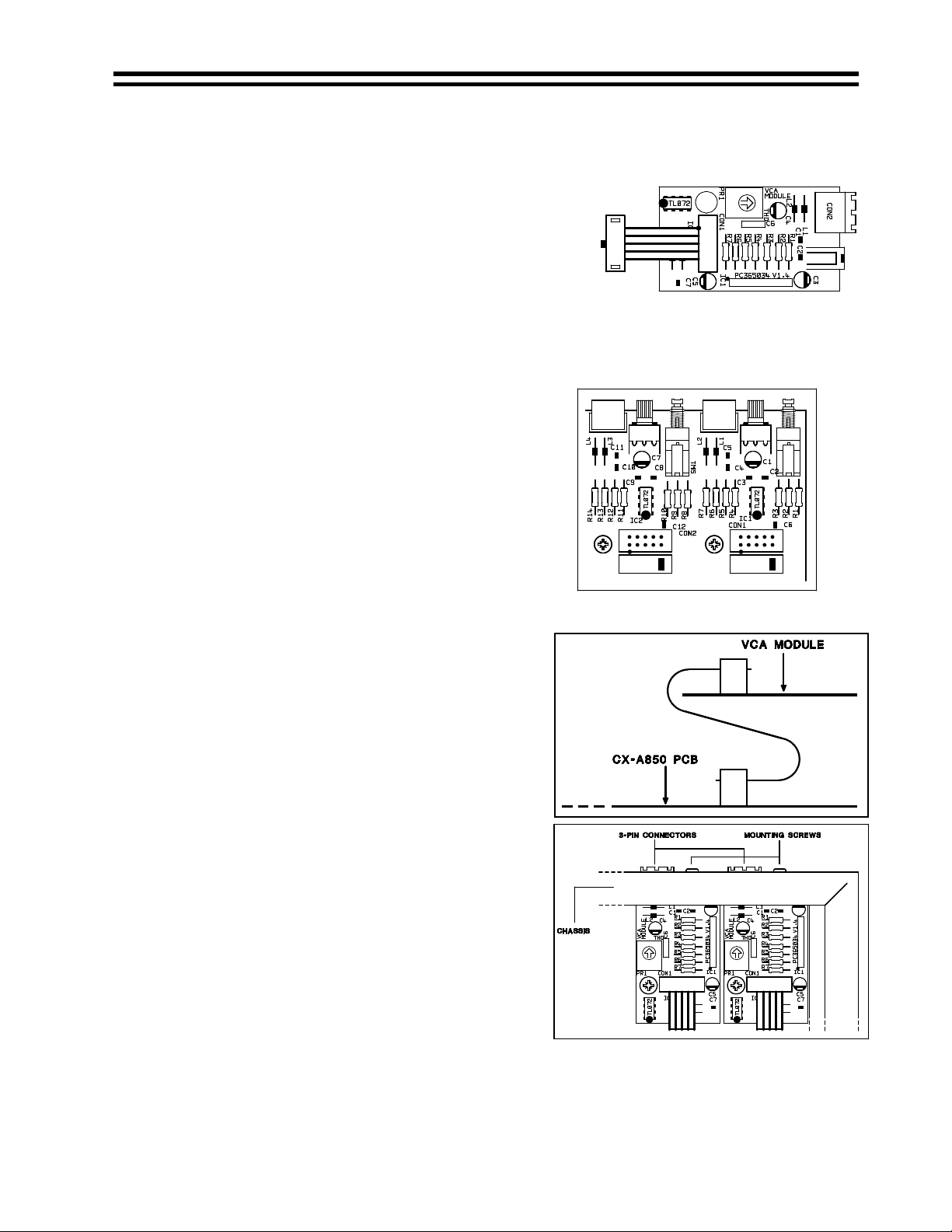
6. Push the 10-way plug from the VCA module onto
the PCB connector aligning the plug so the cable
approaches it from the rear of the chassis (see
diagram to the upper right), check the connector
mates to all 10 pins.
7. Position the 3-pin socket of the VCA-5 through the
cutout in the rear panel so that the hole in the
VCA-5 circuit board aligns over the hex spacer
8. Secure the VCA-5 to the rear panel with the M3
screw provided (see diagram to the lower right).
9. Secure the VCA-5 to the hex spacer with the M3
screw that was removed from the PCB.
10. Fit the top panel.
If you have any further questions please contact our technical staff
(Contact details on front cover)
04-05-05 V3
 Loading...