

Page 1

VCA-2
Installation Guide V2.0
Cloud Electronics Limited
140 Staniforth Road, Sheffield, S9 3HF England
Tel +44 (0) 114 244 7051
Fax +44 (0) 114 242 5462
E-mail
Web site http://www.cloud.co.uk
info@cloud.co.uk
Page 2
VCA-2: Installation Guide 1
VCA-2
Installation Guide
1 Introduction
The VCA-2 is an optional module that fits inside the CX-A4 or CXA6 and provides two channels (1&2 or 3&4 etc) with the facility to
have remote control of the level (using the RL-1 remote level
control). The CX-A4 can accommodate up to two VCA-2 modules
and the CX-A6 can accommodate up to 3 modules. The unit can
control two channels independently or provide stereo attenuation.
• For independent operation of the two channels the ‘solo/link’ switch should be depressed with
a remote level control (RL-1) wired to each 3 pin connector.
• For stereo operation, release the ‘solo/link’ switch and connect a remote level control to the
left connector only
2 Installation Information
The VCA-2 is supplied with two 40mm M3 hex spacers, one plastic insert & two 3-pin screw
terminal plugs. The connectors to install the VCA modules are to the rear of the amplifier
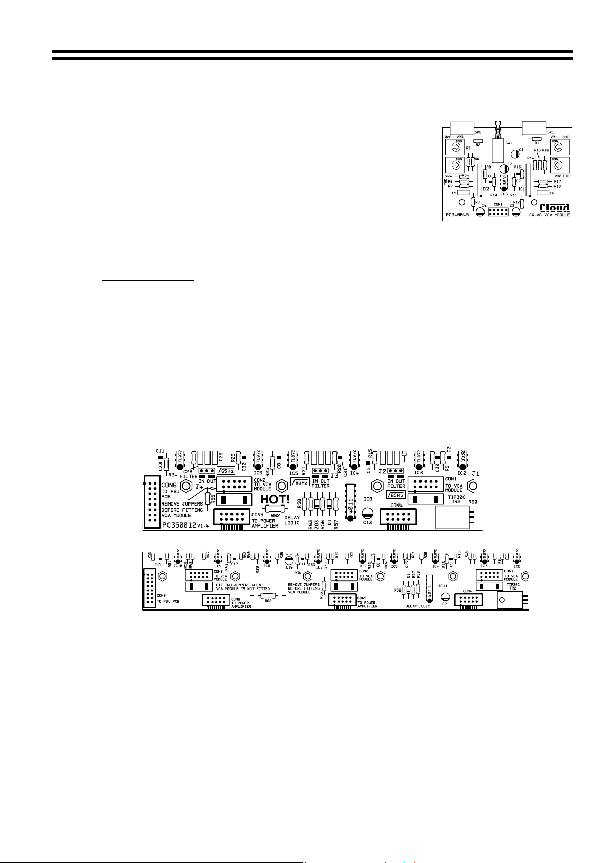
clearly marked on the PCB as ‘CON X TO VCA MODULE’ where ‘X’ is 1,2 or 3 see below: -
CON 1 = Channel 1&2
CON 2 = Channel 3&4
CON 3 = Channel 5&6 (only on CX-A6)
Note: A VCA-2 and Bose
CX-A4
CX-A6
channel.
3 Installation Instructions
1. Turn the power off and remove mains cable.
2. Remove the top panel
3. Select the required PCB mounted VCA connector (see notes above) and remove both
jumpers from it.
4. Remove the relevant blanking plate from the rear panel and push the plastic plug into the
‘clip protect’ hole.
5. Two M3 fixing screws can be found on the motherboard adjacent to the VCA connector.
Remove & retain these screws then fix the 40mm M3 hex spacers in their place.
, as viewed form the rear of the amplifier.
equalisation module cannot be installed together on the same
26-02-02 V2
Page 3

2 VCA-2: I
6. Push the 10-way plug onto this VCA connector aligning the plug so the cable approaches it
from the rear of the chassis (see diagram below), check the connector mates to all 10 pins.
7. Position the 3-pin sockets and switch of the VCA module through the cut-outs in the rear
panel and align the holes in the VCA module over the two 40mm spacers
8. Secure the VCA module to the 40mm spacers with two M3x6 screws (removed earlier)
9. Fit the top panel.
If you have any further questions please contact our technical staff
(contact details on front cover)
Bose
is a registered trademark of The Bose Corporation
NSTALLATION GUIDE
26-02-02 V2
 Loading...