

Page 1

Pump Station 16-R
Installation & User Guide
V2.1
Cloud Electronics Limited
140 Staniforth Road, Sheffield, S9 3HF England
Tel +44 (0) 114 244 7051
Fax +44 (0) 114 242 5462
E-mail
Web site http://www.cloud.co.uk
info@cloud.co.uk
Page 2

Pump Station 16-R: Installation and operation manual 1
Pump Station 16-R
Installation and operation manual
Contents
1 Safety Notes...............................................................................2
Section
Page
3 The RJ45 Connection ................................................................2
4 Schematic Diagram....................................................................3
5 Installation ..................................................................................3
6 RH-8 Installation......................................................................... 3
7 WP-8 Installation ........................................................................ 5
8 Music Inputs ...............................................................................7
9 Sensitivity & Gain Control...........................................................7
10 Global Input................................................................................7
11 Global Input Gain Control........................................................... 7
12 Global Input - High Pass Filter ...................................................8
13 Global Input Priority.................................................................... 8
14 Balanced Line Output – Channel 16 only ...................................8
15 Remote Music Mute – Fire Alarm Interface................................8
16 Chassis Ground Terminal...........................................................9
2 General ......................................................................................2
17 Solving Problems .......................................................................9
17.1 Ground Loops (aka Earth Loops) ............................................... 9
17.2 Connecting balanced signals to the unbalanced line inputs.......9
18 EMC Considerations ................................................................10
19 Technical Specifications...........................................................10
20 General Specifications .............................................................10
16-07-02 V2.1
Page 3

2 Pump Station 16-R: I
1 Safety Notes
• Do not expose this unit to water or moisture
• Do not expose the unit to naked flames.
• Do not block or restrict any air vent
• Do not operate the unit in ambient temperatures above 35
• The unit has no internal user adjustable parts. Do not remove any panel.
• Refer any servicing to qualified service personnel.
• Do not replace the power transformer with any other type
For more detailed information refer to the rear of the manual.
2 General
The Cloud Pump Station 16-R is a headphone distribution processor primarily designed to
provide headphone monitoring of up to eight stereo sound sources to a person using exercise
machines. The Pump Station 16-R has eight stereo line inputs and a balanced ‘global’ input
with priority.
A total of 16 remotely located ‘RH-8’ or ‘WP-8’ remote control units can be wired to the Pump
Station 16-R – the ‘RH-8’ is fitted with a headphone socket, rotary source select switch and
volume control and can be fitted to the exercise machine or wall mounted. The WP-8 however
is a dedicated wall-mounting version of the RH-8 with the provision to connect low power
speakers.
Eight core Category 5 (Cat 5) cable should be used to wire each remote control unit to the
Pump Station 16-R. The RH-8 comes supplied with an RJ45 patch cable that can be
terminated into any RJ45 socket (commonly used as part of a computer network).
A remote music mute facility is also provided on the Pump Station 16-R that may be used to
satisfy the requirements of the Local Fire Officer.
The Sub Station 16-R provides the capacity to add up to sixteen extra RH-8 or WP-8 remote
control devices; the Pump Station 16-R can drive up to 15 Sub Station 16-R units providing a
maximum capacity of 256 control panels. A multi-core expansion cable is supplied with each
unit and the system is wired in the ‘daisy chain’ configuration.
The front panel controls on both units are reduced to a power switch, all the input and output
terminations and gain controls are mounted on the rear panel. The unit can be positioned in a
3 The RJ45 Connection
16-07-02 V2.1
protected area with just the remote control units positioned in the most appropriate location.
The RJ45 plug is a compact 8-pole connector primarily designed for CAT5
cable. Special tools are available making termination both easy and quick.
1) Strip approximately 1” of outer sheath from the cable.
2) Remove extraneous material such as plastic wrap or foil screen from the
8 exposed cores but do not strip their sheaths.
3) Cut the 8 exposed cores down so that when the cable is inserted into the
RJ-45 the outer core can be held by the plugs cable retention system.
4) Insert the 8 cores into the RJ-45 plug fully making sure that they are all
correctly arranged. Information on the correct arrangement of cores for
the RH-8 can be found in section 6 and the WP-8 details are in section 7.
5) Place the plug/cable assembly into the assembly tool and operate the
mechanism.
6) You should now have a firmly connected plug/cable assembly that is
ready for installation.
These notes are for guidance only: always follow the instructions supplied with the assembly tool
NSTALLATION AND OPERATION MANUAL
o
C
Page 4

Pump Station 16-R: Installation and operation manual 3
4 Schematic Diagram
5 Installation
The Cloud Pump Station 16-R is suitable for mounting in a standard 19” equipment rack where
it will occupy two units of rack space. The Pump Station 16-R is 170mm deep, but a depth of
235mm should be allowed to clear the rear panel connectors. When possible, avoid positioning
the unit in close proximity to magnetic fields or equipment operating at a high temperature. The
Pump Station 16-R operates from an external plug-top transformer and a provision should be
made to plug this into a suitably positioned power socket. The Pump Station 16-R is fitted with
an RJ45 socket for each remote control unit; terminate using eight core category 5 cable (4 pair
Cat 5). The total cable length from an RH-8 to the rack should not exceed 100m (328ft).
6 RH-8 Installation
When installing the RH-8 we suggest that an RJ45 data socket is
floor mounted adjacent to each one. Wire each data socket
individually back to the equipment rack pin to pin using CAT 5
cable. The RH-8 is fitted with an RJ45 compatible data socket
and supplied with a 3m patch cord to link to the floor mounted
data socket; this approach simplifies maintenance.
Cable Information for Wiring the RH-8 to a Floor Socket
RH-8 (RJ45) Pump Station 16-R (RJ45) CAT 5*
Pin 8 Pin 8 Brown/White
Pin 7 Pin 7 White/Brown
Pin 6 Pin 6 Green/White
Pin 5 Pin 5 White/Blue
Pin 4 Pin 4 Blue/White
Pin 3 Pin 3 White/Green
Pin 2 Pin 2 Orange/White
Pin 1 Pin 1 White/Orange
Pump Station 16-R & Sub Station 16-R
16-07-02 V2.1
Page 5

4 Pump Station 16-R: I
The RH-8 is supplied with mounting accessories allowing it to be mounted onto the frame of an
exercise machine or fixed to a flat surface such as a wall or bulkhead. When the RH-8 is
mounted onto the framework, two small nylon brackets should be fastened to the body of the
moulding using the nylon rivets provided. With the brackets in place, loop a nylon tie through
each of the two brackets and use these to securely fasten the RH-8 to the frame. To prevent
rotation on smooth surfaces, we suggest that self-amalgamating electrical insulating tape is
wound around the tube before the ties are fitted. The nylon brackets can be fitted in two
positions to suit the exercise machine.
FIT
BRACKET
HERE
NSTALLATION AND OPERATION MANUAL
FIT
BRACKET
HERE
FIT
BRACKET
HERE
When mounted to framework the RH-8 should be positioned at 45
FIT
BRACKET
HERE
o
(see left hand diagram
below), Ideally the RH-8 should also be positioned to one side of the user instead of directly in
front (See right hand diagram below)
When mounted directly on to a wall or perhaps the bulkhead of an exercise machine, it may be
preferable to hard wire a cable directly to the RH-8 using its internal screw terminals, a diagram
and wiring information for this are shown below.
Cable for Hard Wiring an RH-8 to a Pump Station 16-R
16-07-02 V2.1
Cable Information for Hard Wiring the RH-8
RH-8 (Screw Terminals) Pump Station 16-R (RJ45) CAT 5*
Pin 1 Pin 8 Brown/White
Pin 2 Pin 7 White/Brown
Pin 3 Pin 6 Green/White
Pin 4 Pin 5 White/Blue
Pin 5 Pin 4 Blue/White
Pin 6 Pin 3 White/Green
Pin 7 Pin 2 Orange/White
Pin 8 Pin 1 White/Orange
*The CAT 5 colour is described as the dominant colour first with the tracer second.
Page 6
Pump Station 16-R: Installation and operation manual 5
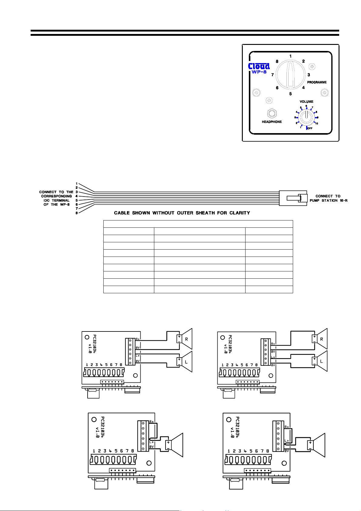
7 WP-8 Installation
The WP-8 is a dedicated wall-mounting unit that has all of the
features of the RH-8 plus a provision for low power speakers.
The module is primarily aimed at applications such as tanning
suites and treatment rooms where users may wish to listen to
music. The WP-8 has two low impedance, low power speaker
outputs each with a different operation:
• The first is a normal low impedance speaker output.
• This second provides a similar low impedance output that is
disconnected when headphones are connected to the WP-8.
The WP-8 should be wired directly to the equipment rack using unscreened ‘Category 5’ cable
(4 pair CAT 5), an IDC insertion tool will be required to connect the WP-8 to the CAT-5 cable.
Cable length should not exceed 100m (328ft).
Cable for Hard Wiring a WP-8 to a Pump Station 16-R
Cable Information for Wiring the WP-8
WP-8 (IDC) Pump Station 16-R (RJ45) CAT 5*
Pin 1 Pin 8 Brown/White
Pin 2 Pin 7 White/Brown
Pin 3 Pin 6 Green/White
Pin 4 Pin 5 White/Blue
Pin 5 Pin 4 Blue/White
Pin 6 Pin 3 White/Green
Pin 7 Pin 2 Orange/White
Pin 8 Pin 1 White/Orange
*The CAT 5 colour is described as the dominant colour first with the tracer second.
The following diagrams show how to wire either speaker output in stereo or mono.
Permanent Speaker Network (Stereo) Switched Speaker Network (Stereo)
Permanent Speaker Network (Mono) Switched Speaker Network (Mono)
16-07-02 V2.1
Page 7

6 Pump Station 16-R: I
NSTALLATION AND OPERATION MANUAL
The WP-8 will provide 150mW of power in stereo configuration and 300mW in mono into 8Ω
speakers. The impedance of the speakers is not critical however the unit will deliver more
power into speakers with an impedance of >8Ω.
Be vigilant when wiring the WP-8 since wiring errors can cause flawed operation. If a problem
is experienced, turn off the power, disconnect the WP-8 and double-check the wiring.
The Cloud WP-8 is designed to be wall mounted. The WP-8 is the same physical size as a
single UK electrical socket (13A Type) and can be mounted in the recessed back box provided
or be surface mounted in a standard 25mm deep housing.
The Cloud WP-8 is fitted with a 3.5mm stereo jack socket that will accept a pair of stereo
headphones. We recommend the use of headphones with 32-ohm impedance for example, the
Cloud CP-32.
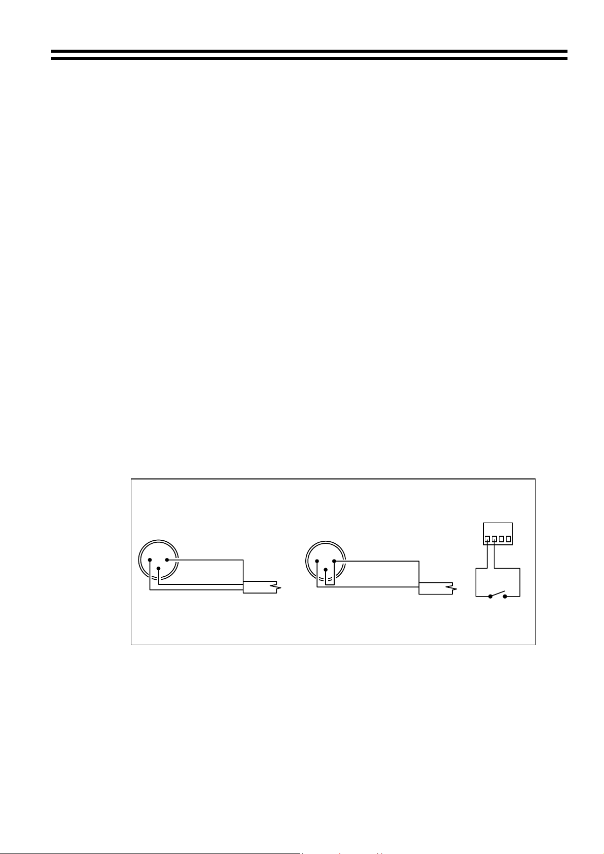
It is also possible to obtain a line level output from the WP-8 by wiring it as follows:
Permanent Line Level Output (Stereo) Switchable Line Level Output (Stereo)
Permanent Line Level Output (mono) Switchable Line Level Output (mono)
The output of the WP-8 can be used to drive a pair of powered speakers if extra volume is
required. The diagram below shows how this can be achieved.
Powered Speaker Output (mono) Powered Speaker Output (stereo)
16-07-02 V2.1
Page 8
Pump Station 16-R: Installation and operation manual 7
8 Music Inputs
The Pump Station 16-R has eight stereo line inputs; these are suitable for most music sources
such as CD players, tape players, satellite receivers and television sets etc. All the stereo
inputs are unbalanced and use RCA type phono sockets. The input impedance is 47kΩ. Try to
plan the installation so that the length of the signal leads is as short as possible.
9 Sensitivity & Gain Control
All eight stereo line inputs have a pre-set gain control on the rear panel, adjacent to the
respective input sockets. The input sensitivity can be varied from –14dBu (155mV) to +6dBu
(1.55V). The pre-set gain controls should be set using the ‘signal’ LED so that all the input
signals operate at the same level within the mixer so that there is no perceivable change in
level when switching sources. Position the pre-set gain control in the fully anti-clockwise
position; rotate the gain control clockwise until the LED illuminates briefly on signal peaks only.
Repeat this process on the other seven inputs. Do not increase the gain control above the
suggested level as this may result in a distorted signal when the RH-8 or WP-8 volume control
is set to the maximum level position.
10 Global Input
A ‘global’ microphone/line input is provided for paging, spot announcements or evacuation
messages. The input amplifier is an electronically balanced, transformer-less design configured
for optimum low noise performance. The ‘global’ signal is routed to all the headphone amplifiers
with automatic, signal sensing priority over the music signal. The ‘global’ signal is fed into the
signal path before the VCA so that any announcement will be heard at the level set by the user.
The input impedance is 5kΩ and is suitable for 600Ω microphones and general line level
signals. The input is via a female 3 pin XLR type connector positioned on the rear panel.
The global input is compatible with general purpose paging microphones fitted with a ‘push to
talk’ switch or open collector switching device. To open the global channel the access switching
terminals should be shorted. If the input is used with other signal sources, it will be necessary to
link pins 1 & 2 on the 4 way screw terminal to open the global input permanently.
2
1
3
BALANCED
GROUND (SCREEN)
REV - PHASE (-)
IN - PHASE (+)
THE GLOBAL INPUT CAN BE USED FOR BOTH MICROPHONE AND LINE SIGNALS
USE THE HIGH PASS FILTER FOR IMPROVED SPEECH CLARITY
For balanced signals, connect the cable screen to pin 1, the in-phase signal (+) to pin 2 and the
reverse phase signal (-) to pin 3.
For unbalanced signals, connect a wire link from pin 1 (ground) to pin 3 inside the XLR cable
mounted plug; use pin 1 as ground (cable screen) and pin 2 as hot.
11 Global Input Gain Control
A pre-set gain control is provided adjacent to the XLR input connector, the gain can be adjusted
from 0dB to 50dB. This large variation in gain allows direct connection to a wide range of
devices from microphones to high output units (such as radio microphones), without the need
for additional attenuation. A high overload margin is maintained at all gain settings.
16-07-02 V2.1
WIRING THE GLOBAL INPUT
2
3
UNBALANCED
1
GROUND (SCREEN)
NO CONNECTION TO PIN 3
HOT (+)
ACCESS
CONTACT
123
4
CLOSE CONTACT TO
OPEN GLOBAL INPUT
Page 9

8 Pump Station 16-R: I
12 Global Input - High Pass Filter
The global input channel features a 3 pole high pass filter operating at 200Hz that can be
switched into the signal path to improve the intelligibility of speech; it also provides effective
attenuation of breath blasts and low frequency handling noises. If the global input is used for
13 Global Input Priority
music signals the filter should be switched to the ‘out’ position.
This feature provides the user with a fully automatic signal sensing input that has priority over
all channels. When a global input signal is detected, the music signals fed to every remote
control unit connected to the system will attenuate by approximately 30dB; once the global
14 Balanced Line Output – Channel 16 only
signal ceases, the music signals will restore smoothly to their former level.
Channel 16 on the Pump Station 16-R is fitted with a balanced line level output using a 3 pin
plug-in screw terminal type connector.
NSTALLATION AND OPERATION MANUAL
GROUND
(SCREEN)
WIRING THE MONO LINE OUTPUT
BALANCED
0V
REV-PHASE (-)
IN-PHASE (+)
(CHANNEL 16 ONLY)
IN-PHASE (+)
GROUND
(SCREEN)
This output satisfies the occasional requirement to provide a signal to a separate sound system
such as a general background music system providing sound within a sports hall or gym. We
suggest that the channel 16 remote control unit be wall mounted in a convenient location. We
do not advocate that any headphones are connected to the remote control unit but the volume
control and source selector can be used to control the signal fed into the separate system.
The nominal output level is 0dBu (775mV). For balanced interconnections, 2 core screened
cable should be used. Connect the screen to left terminal (0V), the centre pin (+) is the in-phase
signal (normally red) and the right terminal (-) is the reverse phase signal (normally blue or
black). If you wish to connect this balanced output to an unbalanced input, connect the cable
screen to (0V) with the hot connection (inner core) connected to the centre pin (+). Make no
15 Remote Music Mute – Fire Alarm Interface
connection to pin on the right (-).
In certain circumstances, there may be a Local
Authority or Fire Service requirement to mute the
music signals via a fire alarm control panel in an
alarm condition. The Cloud Pump Station 16-R
provides a facility to mute the music signals of the
whole system by connecting pins 3 & 4 of the four
pole connector to the contacts of a relay which is
controlled by the fire alarm control panel. The twowire connection should not be connected to any
other circuit or voltage. In most instances, the fire
alarm installation company will provide an auxiliary
relay, normally located close to the sound equipment
rack. The global input will operate normally when
the music mute is operating. (See section 10)
UNBALANCED
0V
NO
CONNECTION
REMOTE MUSIC MUTE TERMINATIONS
RELAY
1
23 4
16-07-02 V2.1
Page 10
Pump Station 16-R: Installation and operation manual 9
16 Chassis Ground Terminal
The rear panel of the Pump Station 16-R is fitted with a Chassis Ground Terminal – this should
be terminated to a convenient earth terminal on the mains distribution system. The termination
is provided for protection purposes; this unit is normally connected to a number of TV sets, FM
receivers and satellite receivers and the grounding of the Pump Station 16-R is a safety
measure to protect the users of the system.
17 Solving problems
17.1 Ground loops (aka Earth loops)
Despite your best efforts, the completed sound system may have some audible ‘hum’, if this is
the case you probably have a ‘ground loop’; this is usually caused by introducing an additional
ground on one of the signal sources. One technique to find the offending signal source can be
undertaken by monitoring the ‘hum’ then disconnecting the input leads (both left & right
channels) on each line input until the ‘hum’ disappears. This problem is often caused by
terminating a screened input cable into a signal source positioned a significant distance from
the mixer. A good way of avoiding this potential problem is to use signal sources (CD players
and the like) that are double insulated with no connection to the mains supply earth. In some
instances the problem can be resolved by insulating the front panel of the signal source from
the equipment rack. If a signal feed is derived from a second mixer (a club or microphone mixer
for example) it would be perfectly normal to expect this to be earthed; we suggest that a
17.2 Connecting balanced signals to the unbalanced line inputs.
16-07-02 V2.1
transformer be used to isolate the signal and prevent a noisy loop.
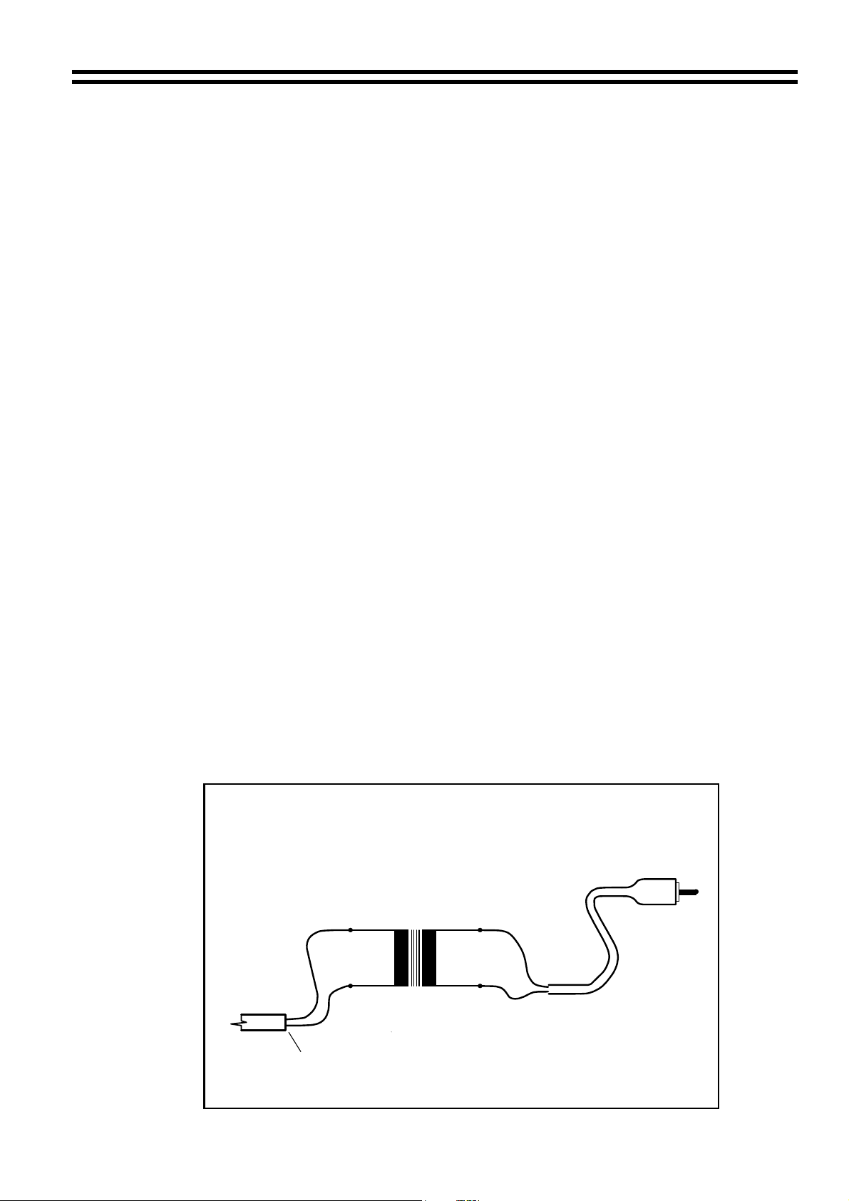
We recommend the use of a transformer to convert a balanced signal to an unbalanced signal
suitable for direct connection to the mixer line inputs. The transformer should be mounted close
to the Pump Station 16-R and the unbalanced output lead should be kept as short as possible.
Where both the source unit and destination mixer are earthed, it is important to isolate the
primary and secondary windings to avoid a potential ground loop; if there is any doubt about
this, we suggest that the balanced cable screen is not connected at the transformer end.
Suitable transformers for this application are the RS Components 210-6447 (primary &
secondary series connected) we recommend the fitting of a screening can also from RS (part
number 210-6469); Canford Audio supply a similar transformer OEP Z1604 we again
recommend that this should be fitted in a similar screened housing. All transformers should be
wired to give a ratio of 1:1. A diagram showing the transformer wiring can be seen below.
BALANCED TO UNBALANCED INTERCONNECTION
INPUT
BALANCED
SIGNAL
INPUT
( WITH ISOLATION TO PREVENT GROUND LOOP )
AUDIO
TRANSFORMER
1 : 1
+
PRIMARY SECONDARY
--
DO NOT CONNECT CABLE
SCREEN AT THIS END
+
SCREEN
HOT
TO MIXER
LINE INPUT
OUTPUT
Page 11

10 Pump Station 16-R: I
18 EMC Considerations
The Cloud Pump Station 16-R fully conforms to the relevant electromagnetic compatibility
(EMC) standards and is technically well behaved; you should experience no operational
problems and under normal circumstances, no special precautions need to be taken. If the unit
is to be used within close proximity to potential sources of HF disturbance such as high power
communications transmitters, radar stations and the like, the performance of the unit may be
reduced. We suggest that the global input cable screen be connected to the shell of the XLR
type connector and the line input leads are kept as short as possible.
19 Technical Specifications
Line Inputs
Frequency response
Input level -14dBu (155mV) to +6dBu (1.55V)
Input impedance 47kΩ
Input gain range 20dB
Input level indicator LED – illuminates above a fixed threshold
Input connector 2 x RCA phono jack (stereo)
Global Input
Frequency response
High pass filter -3dB @ 200Hz – 3 pole (with in/out switch)
Gain range 0dB to 50dB
Input impedance 5kΩ
CMR >70dB @ 1kHz
Access contact Channel off/on by closing contact
Headphone Output – via RH-8
Nominal output level 100mW rms per channel with 32Ω load
Optimum load impedance 32Ω
Recommended headphones Cloud CP32
Headphone Output – via WP-8
Nominal output level 100mW rms per channel with 32Ω load
Optimum load impedance 32Ω
Recommended headphones Cloud CP32
Speaker Output – via WP-8
Nominal output level 150mW rms per channel with 8Ω load
Optimum load impedance >8Ω
Line Output – Channel 16
Nominal output level 0dBu (775mV)
Minimum load 600Ω
20 General Specifications
Pump Station 16-R
Power consumption 25VA with approved external transformer
Width 482.6mm (19.0”)
Height 88.0mm (3.50”) – 2U
Depth 170.0mm (6.70”) + connectors
Weight 4.0kg net
Power Transformer
Output 15V AC 1.25A 18.5VA
Weight 0.52kg net
16-07-02 V2.1
20Hz – 20kHz ±0.5dB
20Hz – 20kHz ±1dB
NSTALLATION AND OPERATION MANUAL
Page 12

Pump Station 16-R: Installation and operation manual 11
This Pump Station 16-R conforms to the following European EMC Standards:
BS EN 55103-1:1997
BS EN 55103-2:1997
This product has been tested for normal use in the commercial and light industrial environment. If the
equipment is used in controlled EMC environments, the urban outdoors, heavy industrial environments
or close to railways, transmitters, overhead power lines etc. the performance of the unit may be
degraded.
The Pump Station 16-R conforms to the following European electrical safety standard.
BS EN 60065:1998
The power transformers for the Pump Station 16-R conform to the following standards:
Power transformer for the UK market (Friwo 11.8367) BS EN60742 + BABT
Power transformer for the European market (Friwo 11.8366) EN60742 + EN60950
Power transformer for USA and Canada (SHOGYO A572710OT) C-UL Approved
Safety Considerations and Information
When the mains switch is in the off ‘O’ position the Pump Station 16-R is disconnected from the
power transformer
CAUTION – Installation
Do not expose the unit to water or moisture
Do not expose the unit to naked flames.
Do not block or restrict any air vent
Do not operate the unit in ambient temperatures above 35
o
C
CAUTION – Servicing
The unit contains no user serviceable parts. Refer servicing to qualified service personnel. Do
not perform servicing unless you are qualified to do so.
Disconnect the power cable from the unit before removing the top or bottom panel
Only reassemble the unit using bolts/screws identical to the original parts
In the interest of continuing improvements Cloud Electronics Limited reserves the right to alter
specifications without prior notice.
Cloud Electronics Limited 140 Staniforth Road Sheffield S9 3HF England
Telephone +44 (0) 114 244 7051 Fax +44 (0) 114 242 5462 E-mail: Info@cloud.co.uk
16-07-02 V2.1
 Loading...