

Page 1

MPA-626
Installation & Operation
Manual
V5.0
Cloud Electronics Limited
140 Staniforth Road, Sheffield, S9 3HF England
Tel +44 (0) 114 244 7051
Fax +44 (0) 114 242 5462
E-mail info@cloud.co.uk
Web site: http://www.cloud.co.uk
Page 2

MPA-626: Installation and Operation Manual 1
MPA-626
Installation and operation manual
Contents
1
2
3
4
4.1 Sensitivity & Gain Control.................................................... 4
4.2 Music Source Select............................................................ 4
4.3 Music Level Control, Local or Remote................................. 4
5
6
7
7.1 Gain Control ........................................................................ 6
7.2 Microphone Input................................................................. 6
7.3 Restoration Relays .............................................................. 7
8
9
Section
Safety Notes
General Description
Schematic Diagram
Music Inputs
Music Equalisation
Music Priority
Microphone Input
Front Panel Level Controls
Microphone Equalisation
............................................................................. 3
................................................................. 3
................................................................. 3
.................................................................. 4
........................................................................... 5
..................................................................... 5
..................................................... 8
........................................................ 8
Page
10
11
12
13
14
14.1 Installation Information..................................................... 10
14.2 Installation Instructions.................................................... 10
15
15.3 Connecting Multiple DM-1 Modules to the Facility Input.. 13
16
17
General Notes
Microphone Priority
10.1 Microphone Over Music Priority......................................... 8
10.2 Mic 1 Over Mic 2 Priority................................................... 8
Chime
Power Amplifier and Line Outputs
12.1 Power Amplifier and Protection Circuits............................. 9
12.2 High Pass Filter ................................................................ 9
12.3 Aux Outputs...................................................................... 9
Music Mute (Fire Alarm Interface)
Bose Equalisation Modules
Facility Input
15.1 AE-1 Facility Connection ................................................. 11
15.2 DM-1 Facility Connection................................................. 12
Facility Input Capacity
........................................................................................ 9
.......................................................................... 10
........................................................................ 14
................................................................. 8
......................................... 9
........................................ 10
.................................................. 10
.......................................................... 14
11-07-02 V4
17.1 Multi-zone Applications.................................................... 14
17.2 EMC Considerations........................................................ 14
Page 3

2 MPA-626: Installation and Operation Manual
17.3 Earthing............................................................................15
17.4 Ventilation.........................................................................15
18
19
20
11-07-02 V4
Technical Specifications
General Specifications
Factory Default Jumper Settings
........................................................15
...........................................................16
..........................................16
Page 4

MPA-626: Installation and Operation Manual 3
1 Safety Notes
• Do not expose the unit to water or moisture.
• Do not expose the unit to naked flames.
• Do not block or restrict any air vent.
• Do not operate the unit in ambient temperatures above 35
• Do not touch any part or terminal carrying the hazardous live symbol ( )
while power is supplied to the unit.
• Do not perform any internal adjustments unless you are qualified to do so and fully
understand the hazards associated with mains operated equipment.
• The unit has no user serviceable parts. Refer any servicing to qualified service
personnel.
• If the moulded plug is cut off the lead for any reason, the discarded plug is a potential
hazard and should be disposed of in a responsible manner.
For more detailed information refer to the rear of the manual.
o
C.
2 General Description
The Cloud MPA-626 is mixer-amplifier with applications in Licensed, Retail and Leisure venues.
The unit has inputs for six stereo line signals and two microphone signals. Front panel controls
are provided for music source selection, music level and microphone levels. All pre-set controls
are located on the rear panel with additional configuration jumpers mounted on the printed
circuit board. A remote level control can be wired to the unit for applications that require remote
control of the music level.
3 Schematic diagram
11-07-02 V4
Page 5
4 MPA-626: Installation and Operation Manual
4 Music Inputs
The unit has six stereo line inputs that are mixed internally to mono; these inputs are suitable for
most music sources such as compact disc players, tape players, satellite receivers and the like.
All inputs are unbalanced and use RCA phono sockets. The input impedance is 47kΩ. The Line
6 input can be configured to have priority over any other music source, see section 6.
4.1 Sensitivity & Gain Control
All six stereo line inputs have a pre-set gain control on the rear panel adjacent to the respective
input socket. The gain control has a range of 20dB allowing the input sensitivity to be varied
from -12dBu (200mV) to +8dBu (2.0V). The pre-set gain control should be set so that all the
input signals are operating at the same level and that the front panel level control has an
optimum range of control.
4.2 Music Source Select
This front panel six position switch is used to select the desired music signal. Use the supplied
label pack to identify the signal sources on the front panel. Line 6 input can be configured to
have priority over any other selected signal, see section 6 for full details.
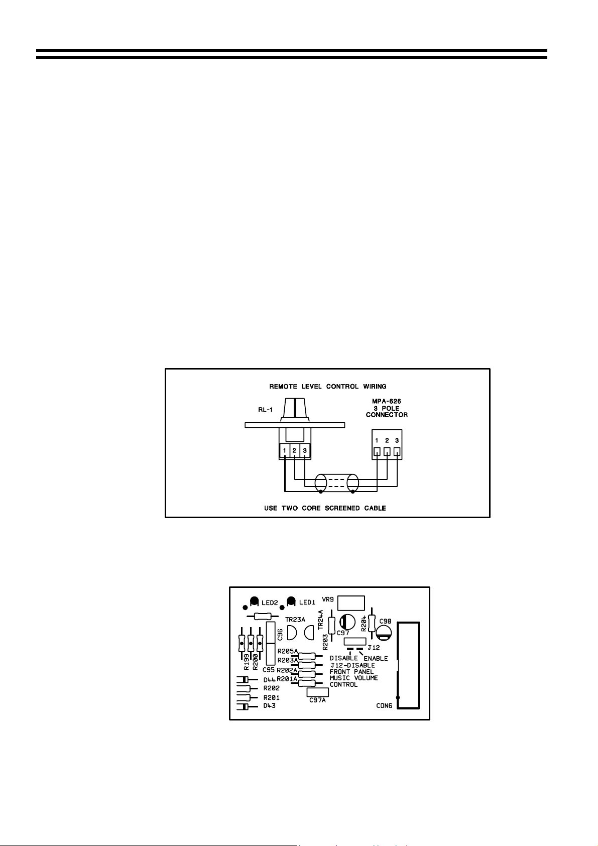
4.3 Music Level Control, Local or Remote
A front panel mounted music level control is provided. Remote control of the music level is
possible by connecting a remote level control plate (RL-1) to the 3 pole connector on the rear
panel of the MPA-626 see the diagram below.
Setting internal jumper J12 to the disable position will disable the front panel level control, see
the diagram below for jumper location. A front panel LED adjacent to the level control will
illuminate to indicate that the control is bypassed. Use two core screened cable to connect the
remote level plate (max length 100 metres).
11-07-02 V4
Page 6
MPA-626: Installation and Operation Manual 5
5 Music Equalisation
One set of independent bass and treble controls is provided for the music signals. These preset controls are located on the rear panel adjacent to the line input sockets. The treble control
has a range of ±10dB at 10kHz and the bass control has a range of ±10dB at 50Hz.
6 Music Priority
When a Juke Box or Spot Announce Player is connected to the MPA-626, fully automatic
priority over any selected line input can be achieved by using the Line 6 input and setting the
rear panel switch L6/PR to ON. When this mode of operation is selected, the unit will operate
normally until a signal is detected on line 6, this causes the selected signal (usually background
music) to mute, allowing the signal on line 6 to operate with priority. Once the signal on line 6
ceases, the selected signal will smoothly restore to its former level. The time taken for the
selected signal to be restored can be set at 3, 6 or 12 seconds by repositioning jumper J13 on
the upper rear printed circuit board.
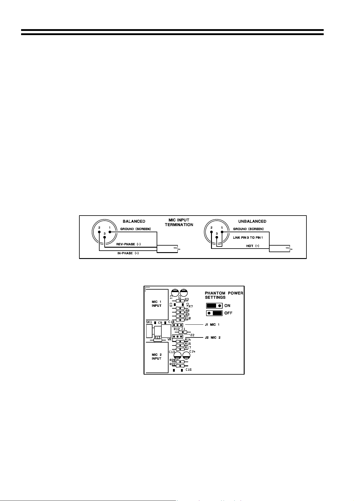
7 Microphone Inputs
Two microphone inputs are provided, the microphone amplifiers are an electronically balanced,
transformer-less design configured for optimum low noise performance. The input impedance is
greater than 2kΩ and is suitable for microphones in the 200Ω to 600Ω range. Inputs are via gold
plated 3-pin XLR type latching connectors, which are positioned on the rear panel. For balanced
microphones, connect the cable screen to pin 1, the in phase signal to pin 2 and the reverse
phase to pin 3. To operate the channel in the unbalanced mode, connect pin 3 to pin 1 (ground)
inside the XLR cable plug. Use pin 2 as hot and pin 1 as screen (ground), see diagram below: -
Phantom power facilities are provided; either of the inputs can be configured to operate with
15V phantom power by setting the relevant jumper to the ON position. Jumper details and
locations are shown in the following diagram : -
Care should be taken to ensure that phantom power is activated only when the microphone
connected to the input requires external phantom power
7.1 Gain Control
A pre-set gain control is provided adjacent to the XLR input connector. The gain can be
adjusted from 20dB to 60dB. A high overload margin is maintained at all gain settings
7.2 Microphone Access Inputs
The microphone access inputs are primarily intended to provide compatibility with paging
microphones and their associated switching arrangements. When these inputs are left open
circuit the microphone inputs are muted. When either terminal 1 or 2 is connected to the 0v
terminal the respective microphone channel will become open for use.
11-07-02 V4
Page 7
6 MPA-626: Installation and Operation Manual
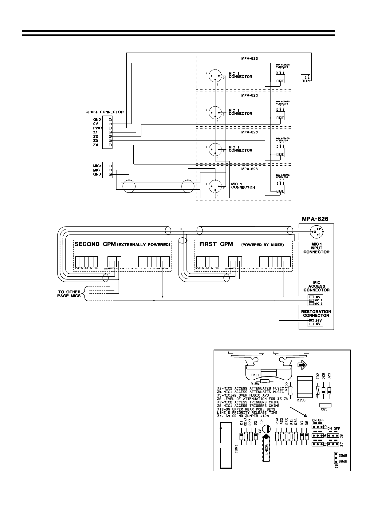
Wiring a CPM-4 to MPA-626 Amplifiers
11-07-02 V4
Wiring Multiple CPM-4 Microphones to an MPA-626
The access inputs can also trigger the following functions:
1. Chime Location of Jumpers J3,4,5,6,7&8
Optional depending upon the setting of
jumpers J8 and J7 for Mic 1 and 2
respectively
2. Muting of music signals
Optional depending upon the setting of
jumpers J4 and J3 for Mic 1 and 2 respectively.
Repositioning Jumper J6 sets the amount of
attenuation for Mic 1&2. The 30dB setting is
intended to provide a 'voice over' function. The
60dB setting has two intended uses:
(i) To provide a more dramatic 'voice over'
during announcements.
(ii) When restoration relays are used they
could increase the volume of the music signal,
the 60dB attenuation will prevent this from
happening.
Page 8

MPA-626: Installation and Operation Manual 7
3. Restoration Relays
The MPA-626 has two restoration relays one activated by Mic 1 access, the other by Mic 2
access. See section 7.3
When the microphone input(s) are to be used without the access feature the microphone
access connector must be fitted with two shorting links, one from 0V to 1 and another from 0V
to 2. The rear panel priority switch must also be in the 'out' position. These settings will ensure
that both microphone channels are open at all times.
7.3 Restoration Relays
There are two restoration relays; one activated by mic 1 access the other by mic 2
access. Whilst the relay contacts are intended for use in restoration in line speaker
systems, the contact ratings are adequate to enable them to switch the low impedance
outputs. All of the relay contacts have been made available on the rear panel connector,
enabling the MPA-626 to work with either 3 wire or 4 wire restoration systems.
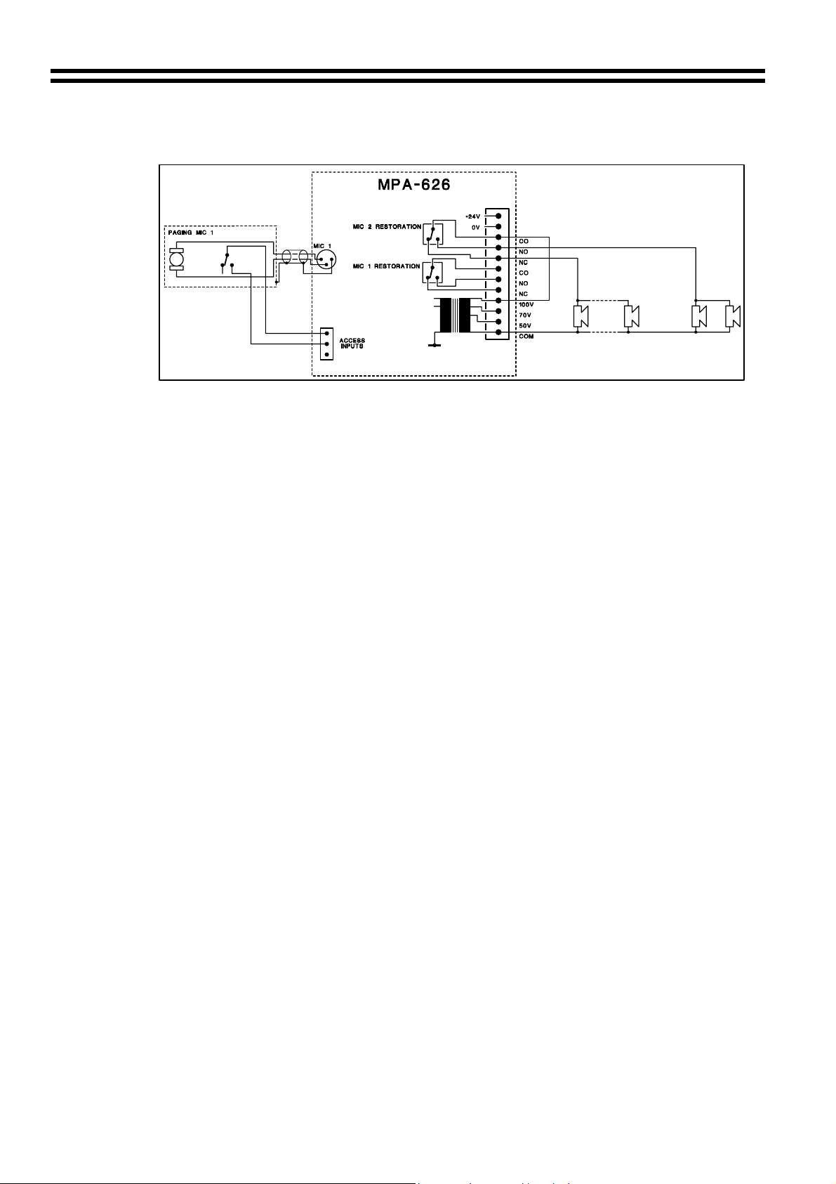
A 24V d.c supply is provided for 4 wire systems. The 24V supply is protected by means
of a 0.4A PTC type thermal fuse, which can be reset by switching off the unit for 15
seconds. In the diagram below the paging microphones are shown with a shorting
switch across the microphone, this is a common feature in such microphones but is not
a requirement with the MPA-626 as the unit contains circuitry that mutes the
microphone inputs when they are not accessed.
Example of a 4-Wire Restoration System.
11-07-02 V4
Example of a 3-Wire Restoration System
Page 9
8 MPA-626: Installation and Operation Manual
The restoration relays may also be used to route the output to specific zones for paging
purposes as shown below.
Using a Restoration Relay to Route the Output
8 Front Panel Level Controls
A separate microphone level control is provided for each microphone input and these provide
the user with a convenient means to operate the microphones at a suitable level. The
microphone signals are routed directly to the aux output and power amplifier and are unaffected
by the operation of the music level control. The gain controls on the rear panel should be set at
a level where it is not possible to have excessive gain even when the front panel level controls
are fully clockwise. Self-adhesive labels are provided to customise the controls.
9 Microphone Equalisation
The microphone channel has both a fixed high pass filter and independent pre-set equalisation
controls positioned on the rear panel. The filter attenuates the signal below 100Hz and the tone
controls provide ±10dB at 100Hz and 5kHz.
10 Microphone Priority
The MPA-626 provides three separate microphone priority functions. Two of these enable the
microphones to have priority over music the other allows Mic 1 to have priority over Mic 2.
10.1 Microphone over music priority
Fully automatic, voice operated priority is provided for the microphone signals. This function can
be selected by means of jumper J5. With this priority function on, when a microphone signal is
detected, the music signal is attenuated, allowing the message to be clearly heard; normal
music operation is restored smoothly after the announcement has been made.
In circumstances where a microphone is switched on by means of the access input the access
input can also be used to trigger a reduction in music level. For Mic 1 this function selected by
J4, for Mic 2 use J3. The amount of attenuation can be set to 30dB or 60dB by means of J6.
For installations using restoration relays it is recommended that this access input priority is
used, with the attenuation set to 60dB. This will prevent any music signals going up and down in
areas where the volume controls have been set low.
10.2 Mic 1 over Mic 2 priority
In situations where the access inputs are used to open both mic 1 and mic 2 the descending
priority feature can be used to give mic 1 priority over mic 2. This is selected by means of a rear
panel switch. When switched on this feature prevents any signal from Mic 2 being broadcast
when Mic 1 is 'accessed'. It should be noted that this feature will allow the user of Mic 1 to cut
off announcements being made using Mic 2.
11 Chime
The MPA-626 has an internal pre-announcement chime generator. The chime can be triggered
by either (or both) Mic access input; this is selected by means of jumper J8 for Mic 1 and J7 for
Mic 2. A rear panel rotary control is provided to set the chime volume. The chime signal is
present on the AUX outputs, low impedance and line outputs.
11-07-02 V4
Page 10

MPA-626: Installation and Operation Manual 9
12 Power amplifier and line outputs
12.1 Power amplifier and protection circuits
The MPA-626 has a 150W output (at the minimum load of 4Ω) power amplifier with a low
impedance output. In order to provide more flexibility the MPA-626 also has an output
transformer that can be switched on via a rear panel switch. When this transformer is switched
on it is strongly recommended that the MPA-626s internal high pass filter be set to 70Hz (see
section 12.2). The transformer provides one additional low impedance output, with a minimum
load of 2Ω. This additional low impedance output is produced using an 'auto transformer' style
primary and is therefore not isolated from the rest of the mixer-amplifier circuitry. The
transformer secondary has 3 line outputs 100V, 70V and 50V, whilst these have a common 0v
connection, they are fully floating i.e. they are isolated from the rest of the amplifier. When the
transformer is in use the maximum total combined load on all outputs should not exceed 120W.
Should the installation require a 25V line the 4Ω low impedance output should be used (150W
into a 4Ω load is approximately 25V rms.)
The MPA-626 power amplifier section contains several protection circuits to protect it from
abuse. A VI limiter is used to protect the amplifier from short circuits and load impedances
below the rated minimum. The Dynamic clip protection reduces the signal level when the
amplifier is driven into clipping, thus limiting any clipping distortion to a set level. An output relay
is used to provide a switch on delay, eliminating switch on 'pops'. This relay is also used to
disconnect the output should the amplifier overheat or if the amplifier develops a fault that gives
rise to a D.C. output. If the amplifier cuts out because of overheating it will reset automatically
after cooling down.
12.2 High pass filter
A high pass filter is provided to protect speakers, transformers etc. from low frequency signals.
This filter has two settings, determined by the position of jumpers J10 and J11 (see diagram
below). The 70Hz setting offers the most protection and ideally it should be used whenever the
output transformer is switched on. The 20Hz setting offers less protection and should be used,
when only the 4Ω output is used i.e. when the output transformer is switched off.
Location of Jumper J10 and J11
12.3 Aux Outputs
Two unbalanced Auxiliary outputs are provided on phono connectors situated on the rear panel.
One of the Aux outputs is at a fixed level, nominally 0dBu (775mV). The level on the other can
be varied from no signal to 0dBu by means of an adjacent rotary control. The nominal output
level is 0dBu (775mV) but the MPA-626 can operate with a wide range of signal levels up to a
maximum output of +20dBu (7.75V). The music level control affects the auxiliary outputs.
11-07-02 V4
Page 11

10 MPA-626: Installation and Operation Manual
13 Music Mute (Fire Alarm Interface)
In certain installations, such as licensed premises or retail
outlets within a shopping mall, there may be a local authority or
fire service requirement to mute the music signals via a fire
alarm control panel in an alarm condition. The MPA-626
provides a facility to mute the music signals only, by using a fully
isolated pair of contacts. This is usually a relay mounted close
to the MPA-626, which is powered by the fire alarm control
panel. The relay should close during an alarm condition (the
installation of this relay is normally undertaken by the fire alarm
installation company). See right hand diagram.
14 Bose Equalisation Module
The single channel Bose equalisation module is compatible
with the MPA-626; it is available in two different models:
• Model 8 card for use with Bose
• Model 32 card for use with Bose model 25, 32 and
102 speakers.
14.1 Installation Information
The connector for the Bose equalisation module is approximately 50mm from the rear of the
variable line out control. The connector is marked CON5 (see diagram below).
Bose Equalisation Module
model 8 speakers.
Location of CON5
Important note: Refer to Section 16 before installing the Bose
14.2 Installation Instructions
1. Switch off power and remove the mains lead.
2. Switch the output transformer on.
3. Remove the top panel from the unit.
4. Remove the jumper from the main PCB connector ‘CON5’.
5. Next to ‘CON5’ there is an M3 screw through the PCB with a white arrow pointing to it, locate
11-07-02 V4
this screw, remove it, retain it and replace it with the 12mm metal hex spacer.
6. Push the Bose
module correctly always using the mounting post to verify correct position of the module.
7. Fit the M3 screw (removed earlier) through the mounting hole into the hex spacer.
8. Replace the top panel.
equalisation module onto the PCB connector; take care to position the
Equalisation module.
Page 12

MPA-626: Installation and Operation Manual 11
15 Facility Input
Each zone has a 9-Pin Sub D-Type connector called ‘Facility Input’ this input allows the
connection of a variety of remote local input modules as detailed in the following sections; 15.1,
15.2 and 15.3.
15.1 AE-1 Aerobics Module
The Cloud AE-1 is a remotely located active module with facilities for line level music and an
unbalanced microphone. The AE-1 can be used for any application where there is a need for a
local music and/or an unbalanced microphone source to be connected to the house system.
The prime application is the fitness suite, where the aerobic instructors are required to connect
their music source and radio microphone directly into the house system. Use 8 core screened
cable to link the AE-1 to the facility input.
Important note: Refer to Section 16 before installing the AE-1.
11-07-02 V4
AE-1 CONNECTION TABLE
Connector Pin Numbers
9 PIN SUB D
AE-1
1 2 3 4 5
N/C 3 8 7 2 5 4 6 3 1
6 7 8 9 SHELL
Page 13

12 MPA-626: Installation and Operation Manual
15.2 DM-1 Dual Microphone Input Module
The Cloud DM-1 is an active remote module with facilities for two balanced microphones. The
DM-1 can be used in any application where local connection and control of two microphones is
required. The prime application is venues that may require the connection of extra microphones
to the house system at any time for speeches, announcements and conferencing etc. In
addition to the separate level controls for each microphone signal, the installer can adjust the
tamperproof EQ that is common to both microphone inputs and select music ducking to
attenuate the level of the house system background music. The DM1 should be wired to the
facility connector with an 8-core cable that has an overall screen.
Important note: Refer to Section 16 before installing the DM-1
11-07-02 V4
DM-1 CONNECTION TABLE
Connector Pin Number
2 3 5 6 8 9
Sub D-Type
DM-1
1 4 7 SHELL
N/C 3 6 2 7 8 4 1 3
5
Page 14

MPA-626: Installation and Operation Manual 13
15.3 Connecting Multiple DM-1 modules to the facility input.
It is possible to connect up to 3 DM-1 modules to the facility input using a ‘daisy chain’.
When two or more panels are connected together in the following ‘daisy-chain’ format the
EQ on the DM-1 ‘closest’ to the host mixer should be used as the master EQ, while all
others should be left neutral. The following diagrams show how two units can be ‘daisy
chained’ for connection to the single facility input.
Note: If you require further information on an active module it can be found in its manual,
available from us upon request.
16 Power Supply Capacity
The existing MPA-626 can supply a total load of 54mA to external active devices and internal
modules. Care should be taken when using external active devices and internal modules with
the MPA-626 amplifier since exceeding the external load capacity risks the power supply cutting
out. The table below lists the current consumption of each compatible MPA-626 external active
device and internal module. Use this table to verify that the external load of your proposed
11-07-02 V4
system falls within the specified limits.
External Active Device / Internal Module Current Consumption
AE-1
DM-1
Bose Equalisation Module
If the 54mA load limit is exceeded the risk of temporary host unit failure will arise. If a failure
occurs switch off the amplifier and disconnect the remote modules, the amplifier should be left
off for approximately 30 seconds to allow it to reset. Check the wiring and total current
consumption of the external active devices before reconnecting the power and if the problem
persists contact our technical department.
9mA @ ±15V
18mA @ ±15V
7mA
Page 15

14 MPA-626: Installation and Operation Manual
17 General Notes
17.1 Multi-zone Applications
Where the sound system specification calls for separate control in several zones, the MPA-626
can be used in multiples. Signal sources can be connected to several inputs as required, but
care must be taken to ensure the output stage of the signal source is capable of driving the
lower impedance load. Line input impedance is 47kΩ and it is reasonable to assume that most
op-amp based signal sources should drive a 10kΩ load, thus allowing up to five parallel circuits.
The input impedance of the microphone amplifier is 2.4kΩ making it suitable for a microphone
with a maximum impedance of 600Ω. A single 200Ω microphone could therefore be connected
to three balanced inputs. To avoid any problems associated with differences in mains supply
earthing, we recommend that all MPA-626's used in a multi-zone application should be located
close together and connected to a common mains supply. Note that when using MPA-626 in
multiples in a 19” rack, ventilation provisions must be made to ensure that the hot air rising from
the ventilation slots of one MPA-626 does not rise up into the unit above it.
17.2 EMC Considerations
The MPA-626 fully conforms to the relevant electromagnetic compatibility (EMC) standards and
is technically well behaved. You should experience no problems interfacing the unit to other
items of equipment and under normal circumstances, no special precautions need to be taken.
If the unit is to be used within close proximity to potential sources of HF disturbance such as
high power communication transmitters, radar stations and the like, it is suggested that the
cable screen be connected to the shell of the XLR type connector and the line input signal leads
be kept as short as possible. Always use balanced interconnections wherever possible. If the
MPA-626 is mounted in a 19" rack, do not locate the unit in close proximity to a powerful
amplifier, which may radiate a strong magnetic field from the power transformer.
17.3 Earthing
The 0V rail of the MPA-626 is coupled to the chassis ground by a parallel resistor/capacitor
network and no interconnection problems should be encountered. When several mains powered
units are connected together via their signal cables, there is a risk of one or more earth loops
which may cause an audible hum on the system even with the gain controls set to minimum.
The 'hum' can be remedied in several ways; the preferred method is to operate interconnects in
the balanced mode wherever possible, with the cable screen only connected at the receiving
end (amplifier input). The signal source units should be located as close as possible to the
MPA-626 and the metal housing of the various units should not be electrically connected
together through the equipment rack. If this is a problem, rack isolating kits are available from
specialist hardware suppliers. If the problem persists, try to connect all interconnected units,
including power amplifiers to a common power source to ensure a common ground is provided.
17.4 Ventilation
The MPA-626 is convection cooled and requires adequate space to allow a free flow of air
through the unit. In 19” rack applications we recommend leaving 1U of rack space above and
below. In free standing applications we recommend fitting the feet supplied and placing the unit
on a flat surface and leaving the ventilation slots on top of the unit free from any obstructions.
18 Technical Specifications
Line inputs
Frequency Response
Distortion
Sensitivity
Input Gain Control
Input Impedance
Headroom
Noise
Equalisation
-3dB 20Hz/70Hz selectable -20kHz ±0.5dB
<0.02% 1kHz
195mV (-12dBu) to 2.0V (+8dBu)
20dB range
47kΩ
>20dB
-89dB 22Hz –22KHz, at speaker output relative to 150W into 4Ω
HF: ±10dB/10kHz LF: ±10dB/50Hz
11-07-02 V4
Page 16
MPA-626: Installation and Operation Manual 15
Microphone Inputs
Frequency Response
Distortion
Gain Range
Input Impedance
Common mode rejection
Headroom
Noise
Equalisation
100Hz / -3dB(filter) 20kHz ±0.5dB
<0.03% 1kHz
40dB
>2kΩ (balanced)
>70dB 1kHz
>20dB
-127dB EIN 22Hz-22kHz (150Ω)
HF: ±10dB/5kHz LF: ±10dB/100Hz
Outputs
Auxiliary Outputs
Speaker Outputs
100V line output
70V line output
50V line output
Protection
Cooling
775mV (0dBu) unbalanced (RCA phono sockets), 1output
fixed level, one variable
150 watts rms/4Ω 105watts rms/8Ω via screw terminals
120 watts rms/2Ω via screw terminals
100 volts balanced – 83Ω min load (120W)
70 volts balanced – 40Ω min load (120W)
50 volts balanced – 21Ω min load (120W)
VI Limiting, DC Offset, Thermal & switch-on delay
Convection
19 General Specifications
Power input
Typical power consumption
Fuse rating
Fuse type
Dimensions (cm)
Weight (kg)
230V ±5% (115V ±5% available) 40 to 60 Hz
160VA
T3.15A for 230V supply T6.3A for 115V supply
20mm x 5mm class 3T 250V
48.26 x 8.80(2U) x 30.00 deep (+ connectors)
8.70kg net
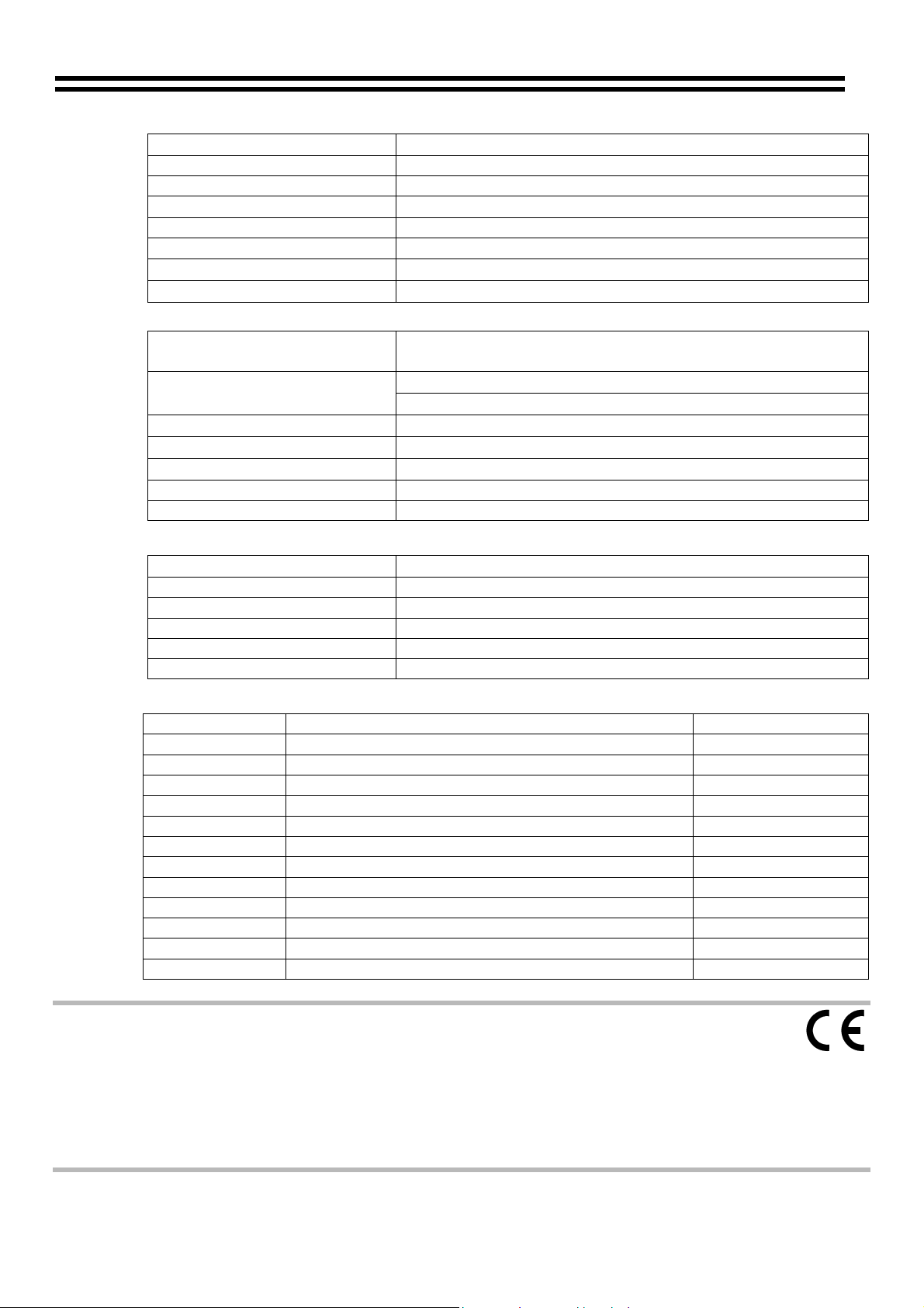
20 Factory Default Jumper Settings
JUMPER FUNCTION DEFAULT SETTING
J1
J2
J3
J4
J5
J6
Mic 1+2 level off access attenuation see J3+J4 30dB
J7
J8
J9
J10+J11
J12
J13
High pass filter frequency 20 or 70 Hz 20 Hz
Disable/enable front panel volume control ENABLE
L6 priority release time 3s, 6s, 12s 6s
This product conforms to the following European EMC Standards:
BS EN 55103-1:1997
BS EN 55103-2:1997
This product has been tested for use in commercial and light industrial environments. If the equipment is used in controlled EMC environments, the urban outdoors, heavy industrial environments or close to railways, transmitters, overhead power lines etc. the performance of the unit may be degraded. The product conforms to the following European electrical safety standard. BS EN 60065:1998
Mic 1 phantom power OFF
Mic 2 phantom power OFF
Mic 2 access attenuates music OFF
Mic 1 access attenuates music OFF
Mic 1+2 auto voice over ON
Mic 2 access triggers chime OFF
Mic 1 access triggers chime OFF
Mic 1 access mutes facility input OFF
11-07-02 V4
Page 17

16 MPA-626: Installation and Operation Manual
Safety Considerations and Information
The unit must be earthed. Ensure that the mains power supply provides an effective earth
connection using a three-wire termination.
When the mains switch is in the off ‘O’ position the live and neutral conductors of the mains
transformer are disconnected.
CAUTION – Installation
Do not expose the unit to water or moisture.
Do not expose the unit to naked flames.
Do not block or restrict any air vent.
Do not operate the unit in ambient temperatures above 35
o
C.
CAUTION – Hazardous Live
Do not touch any part or terminal carrying the hazardous live symb while power is supplied to
the unit.
Terminals to which the hazardous live symbol refers require installation by a qualified person.
ol ( )
CAUTION - Mains Fuse
Replace the mains fuse only with the same type and rating as marked on the rear panel. The fuse
body size is 20mm x 5mm.
CAUTION – Servicing
The unit contains no user serviceable parts. Refer servicing to qualified service personnel. Do not
perform servicing unless you are qualified to do so.
Disconnect the power cable from the unit before removing the top panel and do not make any
internal adjustments with the unit switched on.
Only reassemble the unit using bolts/screws identical to the original parts.
Bose is a registered trademark of The Bose Corporation.
In the interest of continuing improvements Cloud Electronics Limited reserves the right to alter
specifications without prior notice.
Cloud Electronics Limited 140 Staniforth Road Sheffield S9 3HF England
Telephone +44 (0) 114 244 7051 Fax +44 (0) 114 242 5462 E-mail: Info@cloud.co.uk
11-07-02 V4
 Loading...