

Page 1

ME-1
Remote Mic Input Plate
Installation Guide
Introduction
The ME-1 is a remote mic input plate for use with the Cloud DCM-1 Digitally Controlled
Mixer, and cannot be used with any other Cloud product. This document provides
information on how to connect ME-1s into a DCM-1-based audio system. Further
information on conguring the DCM-1 itself for use with ME-1s can be found in the
DCM-1 Installation and User Guide.
The ME-1 allows connection of two separate microphones into a DCM-1-based audio
system. The plate acts as a 2-into-1 mixer, i.e., if both mic inputs are in use, a mono sum
of the two is sent to the DCM-1 for routing to the zone(s).
Cloud Electronics Limited
140 Staniforth Road, Shefeld. S9 3HF. England
Tel: +44 (0)114 244 7051 Fax: +44 (0)114 242 5462
email: info@cloud.co.uk web: www.cloud.co.uk
Page 2
ME-1 Installation Guide v1.02
Introduction - continued
The two microphone channels are identical.
The mic input connector is a 3-pin latching female XLR, wired to the industry-standard
pinout:
PIN FUNCTION
1 Ground
2 Signal ‘hot’ (+, phase)
3 Signal ‘cold’ (-, antiphase)
Phantom power (12v) can be activated by a rear jumper (see below), permitting the
use of either dynamic or condenser microphones. Between -85dB and +60dB of gain
adjustment is available with the faceplate control to suit most types of microphone;
when the plate is in use, mic volume is adjusted with this control alone. HF and LF EQ
adjustment is provided via two screwdriver-operated preset controls; these should
be adjusted using the microphone (and ideally, the speaker him/herself) for optimum
clarity.
See the DCM-1 Installation and User Guide, p33, for details of how an ME-1 input plate
is activated.
Mounting - mechanical
The Cloud ME-1 ts a standard dual-gang electrical back box. The back box used should
have a depth of at least 35mm (1.25”). Note that the ME-1 is made in various faceplate
sizes to suit standard electrical plate sizes in use in the UK, USA and Australia; ensure
you have the correct version for your territory.
Wiring
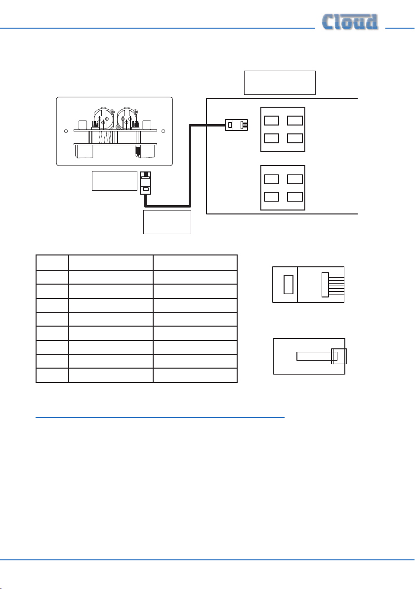
The ME-1’s OUTPUT connector should be connected to one of the DCM-1’s
MICROPHONE INPUTs with screened CAT-5 cable and shielded RJ45 plugs.
Note that because the cables carry low-level audio, only screened CAT-5 should be
used, the foil screen of the cable being bonded to the metal screening can of the plugs.
If an ME-1 is being mounted in close proximity to the DCM-1, it may be possible to
use ready-made screened CAT-5 “patch” cables of an appropriate length. Otherwise,
shielded RJ45 plugs should be crimped onto the installed screened CAT-5 cable using
the pinout shown below.
Page 3
ME-1 Installation Guide v1.0 3
Connect to
Output socket
Screened
CAT-5 cable
Microphone Inputs
Extension Ports
DCM-1
1
2
3
4
1
2
3
4
Connect to an
unused Microphone Input
ME-1
OUTPUT
LINK
PIN USE CAT-5 CORE
1
8
1
8
1
8
1 Mic sum (cold) White + Orange
2 Mic Sum (hot) Orange
3 Sense White + Green
4 DC +ve Blue
5 0v White + Blue
6 DC -ve Green
7 n/u White + Brown
8 n/u Brown
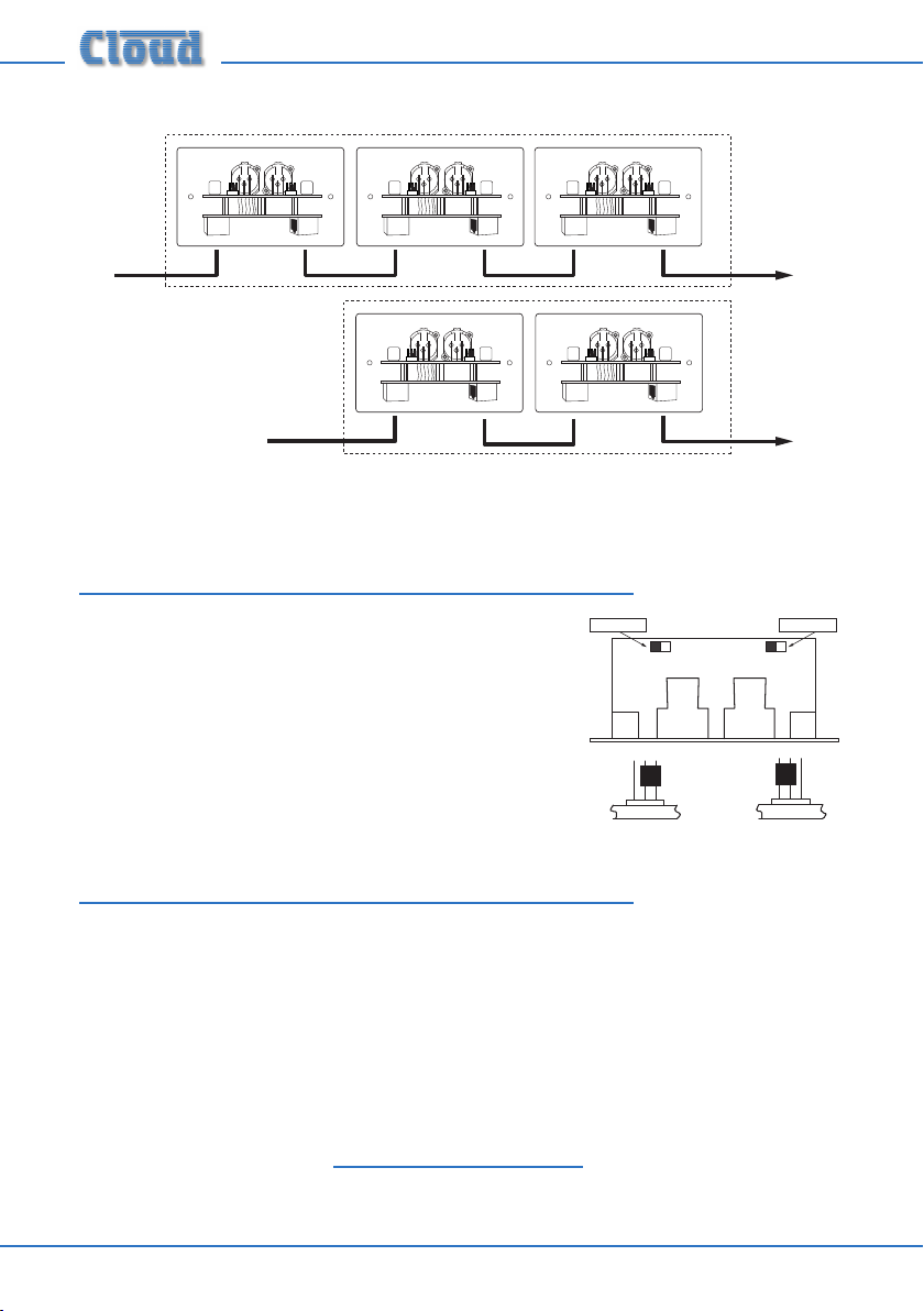
Connecting Multiple ME-1s
Multiple ME-1s may be “daisy-chained” together to provide additional input points,
normally in the same zone. Signals applied to plates wired in this way will be summed
together to the DCM-1 Microphone Input to which the “last” ME-1 in the chain is
connected. An internal gating circuit on each plate automatically “disconnects” any
chained plates which are not in use, to minimise noise contribution. All microphones
plugged into ME-1s on such a chained system will be summed together into one mono
signal.
Multiple ME-1s may be daisy-chained together by connecting the LINK RJ45 socket on
the rst ME-1 (that whose OUTPUT socket is connected directly to the DCM-1) to
the OUTPUT socket on the second ME-1, and so on, as shown on page 4.
Page 4
To DCM-1
Microphone Inputs
(one per zone).
ZONE 1
ZONE 2
Additional
input plates
Additional
input plates
ME-1
OUTPUT
LINK
ME-1
OUTPUT
LINK
ME-1
OUTPUT
LINK
ME-1
OUTPUT
LINK
ME-1
OUTPUT
LINK
(REAR VIEWS)
Phantom power OFF
Phantom power ON
(TOP VIEW)
Channel 1 Channel 2
Phantom power OFF
Phantom power OFF
Phantom power ON
(REAR VIEWS)
Note that it is not possible to intermix ME-1s with either Cloud LE-1 or BE-1 remote
line input plates in this manner.
Phantom Power
12 volt phantom power may be enabled on either input
channel. The installer should determine what type of
microphone(s) are to be used with the ME-1 before
setting these, as inadvertently-applied phantom power
can damage some types of dynamic microphone.
Phantom power is enabled by moving the two jumpers
on the rear pcb, as shown.
DC Power
The ME-1 is powered from the DCM-1’s MICROPHONE INPUTs via the CAT-5
connection. The ME-1 consumes 43mA of current at both +12v and -12v from the
DCM-1 power supply.
If there is any doubt regarding the DCM-1’s spare DC power capacity (as might be the
case in a very large system with many CDR-1 remote controls, level restoration relays,
etc.), please refer to page 53 of the DCM-1 Installation and User Guide where full
details of the DCM-1’s PSU ratings can be found.
Should you have any questions concerning the installation and connection of the
ME-1, please contact our Technical Support staff (details on front cover).
ME-1 Installation Guide v1.04
 Loading...