

Page 1

CXL-50
Installation Guide
V2.0
Cloud Electronics Limited
140 Staniforth Road, Sheffield, S9 3HF England
Tel +44 (0) 114 244 7051
Fax +44 (0) 114 242 5462
e-mail
web site http://www.cloud.co.uk
info@cloud.co.uk
Page 2
CXL-50: Installation guide 1
CXL-50
Installation Guide
1 Introduction
The CXL-50 is a single 70V/100V-line output transformer intended for use in high quality
background music and public address applications in systems up to 40W rms. It can be
externally fitted to the 44/50 Integrated Mixer/Amplifier or CX-A200 Multi-Channel Amplifier.
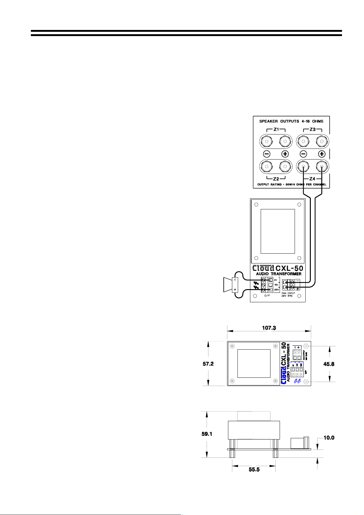
2 Wiring the CXL-50
The CXL-50 should be wired as shown to the right
with the installer using the 70V or 100V output. The
70V/100V-line system is capable of delivering an
electric shock and must be installed with the
appropriate level of care. The cable used to connect
the power amplifier to the CXL-50 should be at least
1.5 mm² and the 70V/100V line cable must be
0.75mm² or more, double insulated and capable of
carrying at least 1A rms. With long distances it may
advantageous to use thicker cable. The CXL-50 is
not of the auto transformer type and hence provides a
fully balanced output signal which is isolated from the
amplifier.
3 Signal Requirements
The CXL-50 may be used at full power with
frequencies down to 50Hz. If it is operated with high
level input signals at frequencies below 50Hz it may
saturate and cause the driving amplifier’s VI limiter to
operate. Care must be taken to ensure that high level
low frequency input signals (50Hz and below) are
removed from the signal when using a CXL-50.
4 Mechanical Installation
The CXL-50 is supplied with four M3 x 6 fixing
screws and a cable tie. The transformer is
mounted on a PCB with screw terminal
connectors, connector cover and M3 fixing
bushes. The CXL-50 must be mounted in a
suitable enclosure (CXL-600 for up to 6 CXL50s) to meet the required safety standards.
No special ventilation provisions need to be
made for the CXL-50 as its high efficiency
means little power is dissipated. The CXL-50
should not be mounted close to mains
transformers or any other source of strong
magnetic fields. If mounting close to mains
transformers is unavoidable then the cores
should be arranged at 90 degrees to each
other.
44/50 & CX-A200 Output Wiring (Zone 4)
CXL-50 Dimensions
16-07-02 V2
Page 3

2 CXL-50: Installation guide
4 The CXL-600
The CXL-600 is available to provide convenient mounting of up to six CXL-50 100V-line
transformers into a 19” rack enclosure and includes provision for neatly tying cables. The CXL600 is not intended to be used free standing and will not provide adequate protection in such a
situation. See right for the dimensions of the CXL-600. The CXL-600 is designed for static
applications only extra support may be required in portable equipment.
CXL-600 Dimensions
5 Technical Specifications
Maximum Input Voltage
Input Impedance
Output power rating
Minimum load impedance
Distortion
The CXL-50 is an accessory for specific cloud products, when installed to these products the
CXL-50 will conform to the relevant European Electrical Safety and EMC Standards
CAUTION - Installation
THE CXL-50 SHOULD BE MOUNTED IN AN ELECTRICALLY SAFE ENCLOSURE THAT
MEETS THE REQUIREMENTS OF BS EN 60065.
THE INSTALLATION OF THE CXL-50 IS BEYOND THE CONTROL OF CLOUD
ELECTRONICS Ltd AND WE ACCEPT NO RESPONSIBILITY FOR HAZARDOUS
INSTALLATIONS.
In the interest of continuing improvements Cloud Electronics Limited reserves the right to alter
specifications without prior notice.
Cloud Electronics Limited 140 Staniforth Road Sheffield S9 3HF England
Telephone +44 (0) 114 244 7051 Fax +44 (0) 114 242 5462 E-mail: Info@cloud.co.uk
16V rms
4 Ohms (with 250 Ohm secondary load)
40W rms
250 Ohms
Typically 0.03% @ 1kHz
16-07-02 V2
 Loading...