

Page 1
CXL-4160
100/70 V Transformer Module
Installation Instructions
Important Safety Notes
It should be recognised that 100 V-line or 70 V-line speaker systems have the
potential to deliver an electric shock. Install the CXL-4160 only in accordance
with these instructions.
In all cases, the external wiring and associated speakers will need to comply
with local electrical regulations for AC voltages up to 100 Vrms (141 Vpeak).
Do not expose the transformer to rain or moisture.
The transformer module must be installed in a safe manner.
Cloud Electronics Ltd. accept no responsibility for hazardous installations.
CXL-4160 Installation Instructions v1.0 1
Page 2
INTRODUCTION
The CXL-4160 is an optional transformer module for the 46-50 Multi-Zone Mixing Amplier. It permits the 46-50 to directly drive
100 V or 70 V-line loudspeaker systems. The module itself consists of four transformers (one for each Zone output) mounted on
a PCB, and is supplied in kit form with all the necessary xings and wiring. Any or all of the 46-50’s outputs may be converted to
70/100 V-line operation as wished. Each transformer is rated at 40 W.
The CXL-4160 transformers are not of the “auto transformer” type, and hence provide a fully balanced output signal which is
isolated from the amplier.
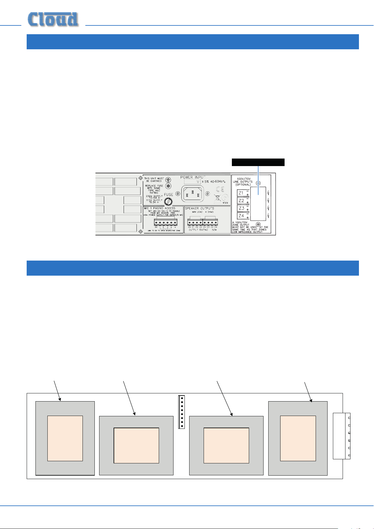
The module is easily mounted within the 46-50’s enclosure, using pre-drilled xing holes. The outputs are then available on an
8-way parallel entry screw-terminal connector which occupies the hole (shown below) in the rear panel normally covered by a
blanking plate.
CXL-4160 Outputs
46-50 Rear Panel
FITTING THE CXL-4160 TRANSFORMER MODULE
The module kit comprises the following items:
• CXL-4160 transformer module PCB assembly
• 8qty M3 x 6 mm xing screws (black)
• 2qty M3 x 6 mm xing screws (bright)
• 2qty M3 x 10 mm hex pillars
• 8-pin to 4 x 2-pin cable assembly, with connectors
• 2qty cable ties
TX1 - Zone 1 TX4 - Zone 4TX3 - Zone 3 TX2 - Zone 2
CXL-4160 transformer module PCB assembly
CXL-4160 Installation Instructions v1.02
Page 3
Proceed as follows:
IMPORTANT: The CXL-4160 is preset at the factory for either 100 V-line or 70 V-line
operation, according to territory. The relevant voltage is clearly indicated on the label on the
outside of the box.
If the alternative operating voltage is needed, refer rst to the manual section “Changing the
CXL-4160 between and 100 V-line and 70 V-line operation”.
1. Disconnect the 46-50 from the mains. If it is tted in a rack, disconnect all inputs and outputs and remove it from the rack.
Orientate the unit with the rear nearest to you. Remove the top cover; retain the eight xing screws.
2. Remove the blanking plate from the 100V/70V LINE OUTPUTS connector location on the rear panel; retain the plate and
screws, nuts and washers.
3. Identify the eight empty M3 holes on the right-hand side of the 46-50’s enclosure (as viewed from the rear). The CXL-4160
module is xed using these holes and the eight hex spacers tted to the rear of the PCB. Align the spacers with the holes, and
x with the eight black M3 screws supplied. The output connector should protrude neatly through the punch-out vacated in
Step 2.
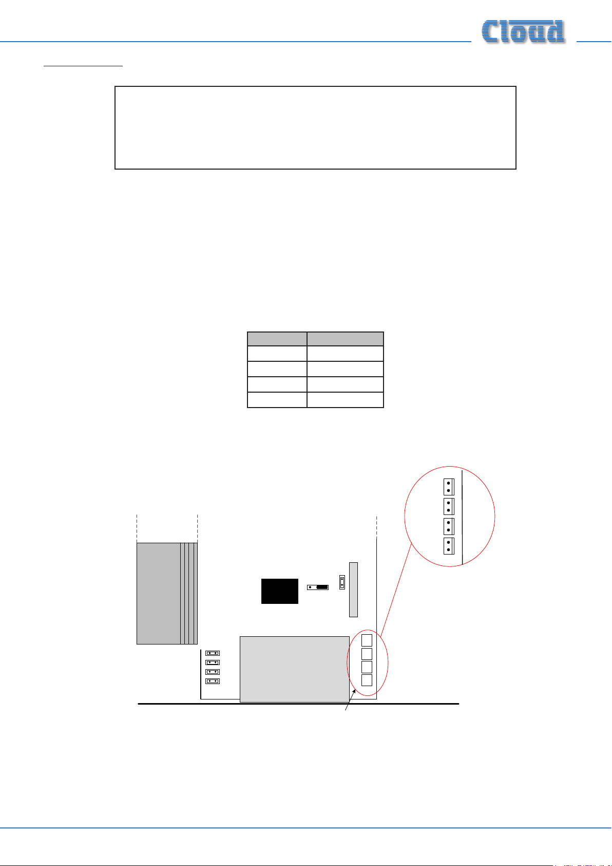
4. Fit the supplied cable assembly: the 8-pin header on the CXL-4160 PCB is connected to the four 2-pin headers on the 46-50
main PCB, located immediately behind the 100V/70V OUTPUTS connector location - see below. Note that the wire pairs
are colour coded for clarity:
ZONE PAIR COLOUR
ZONE 1
ZONE 2
ZONE 3
ZONE 4
Mauve
Grey
Blue
Black
Note that any or all of the four channels may be converted as required.
CON 8
assy.
REAR PANEL
MAIN PCB
MAINS INPUT SUB-BOARD
Connectors for CXL4160 transforme r
ZONE 1
ZONE 2
ZONE 3
ZONE 4
CXL-4160 Installation Instructions v1.0 3
Page 4

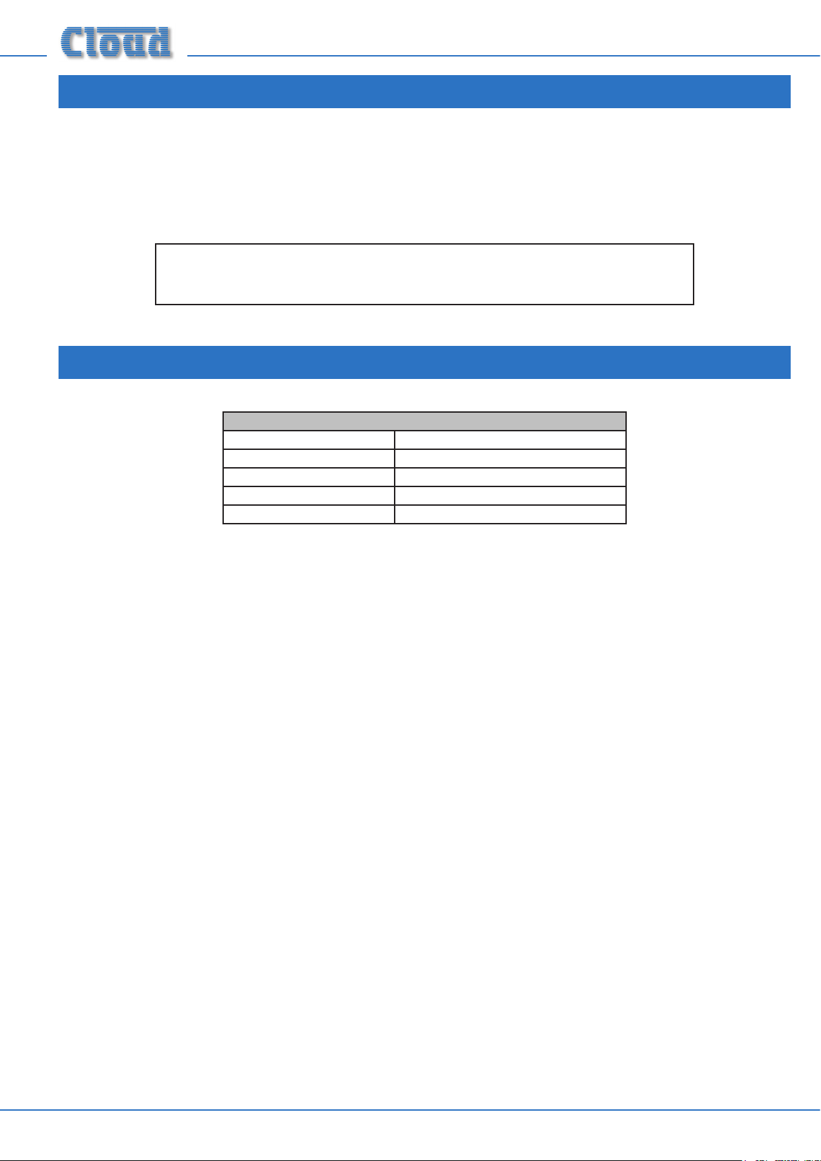
5. On the 46-50’s main PCB, enable the 65 Hz high-pass lters for the relevant channels. This is important, as low frequency
signals at high level can saturate the transformer cores, causing unpleasant distortion and possibly activating the amplier’s
limiter circuitry. The jumpers are as follows:
OUTPUT JUMPER
ZONE 1
ZONE 2
ZONE 3
ZONE 4
J7
J9
J16
J18
The approximate locations of the jumpers are shown in the illustration below.
J16
J9
J7
LINE INPUT SUB-BOAR D
CON 4
CON 3
NOT TO SCALE – ONLY PRIMARY
COMPONENTS SHOWN
J18
CON 7
CON 8
Connectors for
CXL4160 transformer
assy.
46-50 Jumper locations.
6. Fit the two hex spacers supplied in the kit into the holes vacated in Step 2, using the same screws, nuts and washers.
7. Replace the 46-50 top cover, and reinstall in the rack (If necessary); reconnect all inputs and outputs.
8. Connect the 70/100 V-line loudspeaker system to the rear connector (see section: “Output wiring”) according to the table
below:
PANEL MARKING CONNECT TO:
1 Z1+
2 Z1-
3 Z2+
4 Z2-
5 Z3+
6 Z3-
7 Z4+
8 Z4-
Zone 1 output ‘+‘
Zone 1 output ‘-‘
Zone 2 output ‘+‘
Zone 2 output ‘-‘
Zone 3 output ‘+‘
Zone 3 output ‘-‘
Zone 4 output ‘+‘
Zone 4 output ‘-‘
9. Fit the blanking plate from Step 2 onto the hex spacers (Step 6) over the connector using the bright M3 screws, with the
printed warnings outwards.
10. The 46-50 may now be reconnected to the AC mains and re-powered.
CXL-4160 Installation Instructions v1.04
Page 5

OUTPUT WIRING
The cable used for the 70/100 V-line system must be 0.75mm² or more, double insulated and be capable of carrying at least 1 Arms.
When long distances are involved, it may be advantageous to use cable with a higher cross-section.
The 46-50’s low-impedance outputs remain active after the CXL-4160 has been
installed, but should NOT have a load connected to them while the 70/100 V-line
outputs are in use.
CHANGING THE CXL-4160 BETWEEN
100 V-LINE AND 70 V-LINE OPERATION
The secondary windings of the transformers used in the CXL-4160 module are tapped at 70 V and 100 V. The module will be
supplied pre-congured for the voltage normally used in your territory. To use the 46-50 with the “alternative” line system voltage,
the tapping must be changed. This is done by moving soldered wire links on the rear of the module PCB. There is one link for each
transformer.
NOTE: This operation should only be performed by someone experienced in PCB soldering.
The diagram below indicates the location of the solder links for each transformer:
Transformers configured for 100 V-line operation
100 V
70 V
ZONE 2
OUTPUT CONNECTOR
100 V
70 V
ZONE 2
100 V
100 V
ZONE 4
70 V
Transformers configured for 70 V-line operation
Transformers configured for 70 V-line operation
ZONE 4
100 V
ZONE 3
100 V
70 V
ZONE 1
70 V
100 V
70 V
ZONE 1
70 V
SOLDER SIDE OF PCB, SHOWING APPROX. LOCATIONS OF WIRE LINKS
100 V
ZONE 3
70 V
Unsolder the links from their existing pairs of pads and re-solder them to the other pair. A desoldering tool may be helpful in
removing excess solder. Take care not to make any accidental solder “bridges” between other pads.
CXL-4160 Installation Instructions v1.0 5
Page 6
SAFETY NOTES REGARDING INSTALLATION
The CXL-4160 is an accessory for the Cloud 46-50, and when installed in this product, conforms to the relevant European
Electrical Safety and EMC Standards.
The CXL-4160 is specically designed to be tted internally in the 46-50. Should the CXL-4160 be mounted in any other
enclosure, the enclosure must be electrically safe and meet the requirements of BS EN 60065.
THE INSTALLATION OF THE CXL-4160 IS BEYOND THE CONTROL OF
CLOUD ELECTRONICS LTD., AND WE ACCEPT NO RESPONSIBILITY FOR
HAZARDOUS INSTALLATIONS.
TECHNICAL SPECIFICATIONS
CXL-4160; EACH TRANSFORMER
Maximum input voltage 16 Vrms
Input impedance 4 ohms (with 250 ohm secondary load)
Output power rating 40 W
Minimum load impedance 250 ohms
Distortion <0.03% @1 kHz
CXL-4160 Installation Instructions v1.06
Page 7

Cloud Electronics Limited
140 Staniforth Road
Shefeld S9 3HF
England
Tel: +44 (0)114 244 7051
Fax: +44 (0)114 242 5462
email: info@cloud.co.uk
web: www.cloud.co.uk
Cloud Electronics USA
1200 Iron Horse Drive, Unit A
Park City
Utah 84060.
United States of America.
Toll Free: 0855 810 0161
email: sales@cloudusa.pro
web: www.cloudusa.pro
 Loading...