

Page 1

CXL-400
Installation Guide
V 2.0
Cloud Electronics Limited
140 Staniforth Road, Sheffield, S9 3HF England
Tel +44 (0) 114 244 7051
Fax +44 (0) 114 242 5462
E-mail
Web site http://www.cloud.co.uk
info@cloud.co.uk
Page 2
CXL-400: Installation guide 1
CXL-400
Installation & User Guide
1 Introduction
The CXL-400 is a 100/70V-line module consisting of 4 transformers intended for use in high
quality background music and public address systems up to 40W rms. It can be installed
2 Installation Information
3 Signal Requirements
4 44/50 Installation Instructions
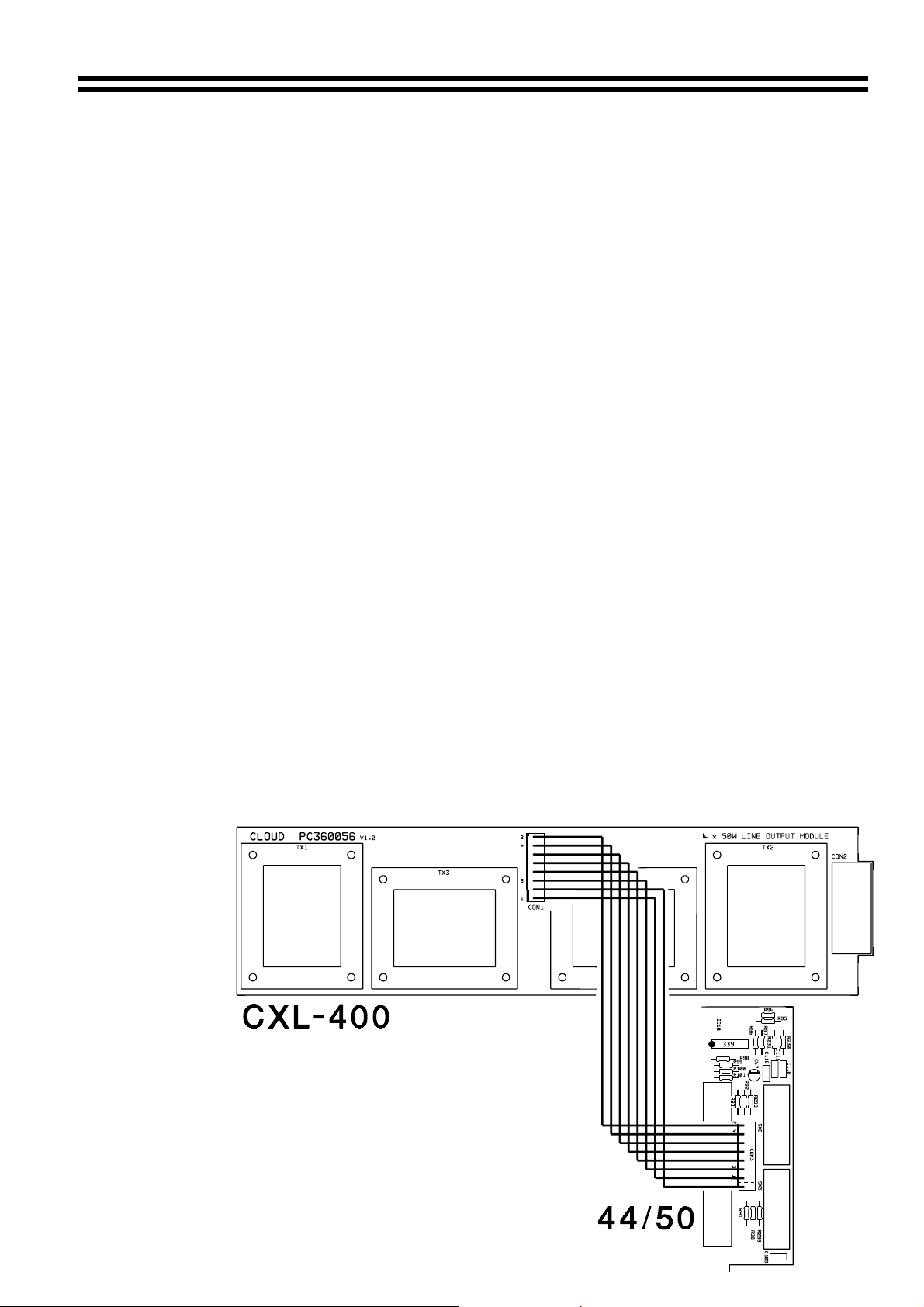
NOTE: If you wish
to disable a
transformer on
any zone simply
remove its
relevant wire, from
the 8-way
connector. The
zone numbers are
clearly marked
near the connector
on the CXL-400
and 44/50 PCB
(See diagram on
right).
internally to the 44/50 and CX-A200.
The CXL-400 is supplied with 10 M3×6 screws an 8-way cable and 2 10mm M3 hex spacers.
The transformers are mounted on a PCB with M3 fixing bushes and screw terminal output
connectors. The CXL-400 is fitted inside the 44/50 and CX-A200.
70V/100V-line systems are
capable of delivering an electrical shock so must be wired with the appropriate level of care.
The CXL-400 can be used at full power with frequencies down to 50Hz. If it is operated with
high level input signals at frequencies below 50Hz it may saturate and cause the driving
amplifier’s VI limiter to operate. Care must be taken to ensure that high level low frequency
input signals (50Hz and below) are removed from the signal when using a CXL-400.
1. Turn the power off and remove the mains cable
2. Remove top panel
3. Remove the mains socket and mains switch from the chassis leaving the wires connected
4.
Set the relevant transformers (see below) to 70V operation if required by moving the solder
link on the underside of the PCB from 100V to 70V, the factory default is 100V.
TX1 = Zone 1, TX2 = Zone 4, TX3 = Zone 3 & TX4 = Zone 4
5. Carefully place the CXL-400 board in the chassis alongside the power supply transformer
with the output connector protruding through the rectangular cut out in the rear of the chassis
and the transformers facing inside the chassis.
6. Secure the CXL-400 to the side of the chassis with the 8 provided M3×6 screws.
7. Reinstall the mains switch and socket
8. Connect the CXL-400 to the main board using the 8-way cable (see note).
9. Replace the top panel and fit the protective cover over the outputs of the CXL-400 using the
two 10mm M3 hex spacers and remaining two screws
Wiring Between CXL-400 and 44/50
16-07-02 V2
Page 3

2 CXL-400: Installation guide
5 CX-A200 Installation Instructions
1) Turn the power off and remove the mains cable
2) Remove top panel
3) Remove spade terminals from the Mains Switch (taking note of the wiring) then remove the
switch from the front panel.
4) Set the relevant transformers (see below) to 70V operation if required by moving the solder
link on the underside of the PCB from 100V to 70V, the factory default is 100V.
TX1 = Channel 1, TX2 = Channel 2, TX3 = Channel 3 & TX4 = Channel 4
5) Carefully place the CXL-400 board in the chassis alongside the power supply transformer
with the output connector protruding through the rectangular cutout in the rear of the chassis
and the transformers facing inside the chassis.
6) Secure the CXL-400 to the side of the chassis with the 8 M3×6 screws.
7) Rewire the mains switch
8) Connect the CXL-400 to the main board with the 8-way cable (see note).
9) Replace top panel and fit the protective cover over the outputs of the CXL-400 using the two
10mm M3 hex spacers and remaining two screws
Wiring Between CXL-400 and CX-A200
*NOTE: Should you wish to disable a transformer on any channel simply remove the relevant
wire, from the 8-way connector. The channel numbers are clearly marked near the 8-way
connector on both the CXL-400 and CX-A200 PCB.
6 Output Cable Requirements
The cable used for the 70V/100V-line output must be 0.75mm2 or more, double insulated and
capable of carrying at least 1A rms. With long distances, it may be advantageous to use thicker
cable. The CXL-3120 transformers are not of the auto transformer type and hence provide a
fully balanced output signal which is isolated from the amplifier.
11-01-02 V1
Page 4

CXL-400: Installation guide 3
7 Technical Specifications
Maximum Input Voltage
Input Impedance
Output power rating
Minimum load impedance
Distortion
4 Ohms (with 250 Ohm secondary load)
Typically 0.03% @ 1kHz
The CXL-400 is an accessory for specific cloud products, when installed to these products the
CXL-400 will conform to the relevant European Electrical Safety and EMC Standards
16V rms
40W rms.
250 Ohms
CAUTION - Installation
THE CXL-400 IS SPECIFICALLY DESIGNED TO BE FITTED INTERNALLY TO THE 44/50
AND CX-A200, SHOULD THE UNIT BE MOUNTED IN ANY OTHER ENCLOSURE, THE
ENCLOSURE MUST BE ELECTRICALLY SAFE AND MEET THE REQUIREMENTS OF BS
EN 60065.
THE INSTALLATION OF THE CXL-400 IS BEYOND THE CONTROL OF CLOUD
ELECTRONICS Ltd AND WE ACCEPT NO RESPONSIBILITY FOR HAZARDOUS
INSTALLATIONS.
In the interest of continuing improvements Cloud Electronics Limited reserves the right to alter
specifications without prior notice.
Cloud Electronics Limited 140 Staniforth Road Sheffield S9 3HF England
Telephone +44 (0) 114 244 7051 Fax +44 (0) 114 242 5462 E-mail: Info@cloud.co.uk
16-07-02 V2
 Loading...