

Page 1

CX233 Zoner Mixer
Installation & User Guide
Cloud Electronics Limited
140 Staniforth Road, Sheffield, S9 3HF England
Tel +44 (0)114 244 7051
Fax +44 (0)114 242 5462
e-mail
web site http://www.cloud.co.uk
info@cloud.co.uk
Page 2

CX233 I
NSTALLATION AND OPERATION MANUAL
CX233 Zone Mixer
Installation and operation manual
Contents
Section Page
1 General description....................................................................2
2 Music inputs ...............................................................................2
2.01 Music inputs.....................................................................2
2.02 Gain Control.....................................................................2
2.03 Front panel level controls.................................................2
2.04 Priority..............................................................................2
3 Microphone inputs......................................................................2
1
3.01 Mic inputs...........................................................................2
3.02 Gain Control.....................................................................3
3.03 Front panel level controls.................................................3
3.04 Priority..............................................................................3
3.05 Equalisation.....................................................................3
3.06 Emergency Mode.............................................................3
4 Zone Outputs..............................................................................3
4.01 Zone outputs....................................................................3
4.02 Equalisation.....................................................................3
4.03 Stereo/Mono Operation...................................................4
5 VCA Modules .............................................................................4
5.01 VCA Modules...................................................................4
5.02 Fitting VCA Modules........................................................4
5.03 Remote level Plate
6 Optional DC Power Supply.........................................................5
6.01 Optional DC to DC Power Supply.......................................5
6.02Fitting of DC to DC Power Supply .......................................6
7 Fire Alarm Interface ( Remote Music Mute) ................................6
8 Mic 2 Emergency Mode..............................................................6
9 Earthing......................................................................................6
10 Unbalanced Mode......................................................................7
11 Technical Specifications.............................................................7
Page 3

2 CX233 I
1 General Description
The CX233 is a versatile multi-source mixer/zoner that can be used with confidence as
part of a professional sound system. The impressive performance and flexible routing
options together with the remote level control facility make it suitable for a wide range of
applications. In addition, the fire alarm mute facility, emergency microphone mode and
DC power supply option make the mixer/zoner well equipped to satisfy local authority and
fire department requirements.
2 Music Inputs
2.01 Music Inputs
All three line inputs have a flat frequency response and are suitable for most music
sources such as compact disc players, tape players and tuners etc. Unbalanced signals
make use of RCA phono sockets and balanced inputs use XLR connectors. The nominal
input sensitivity is 0dBu (775mV) ñ12dB.
NSTALLATION AND OPERATION MANUAL
2.02 Gain Control
All music inputs have pre-set gain controls mounted on the rear panel adjacent to the
input connectors. The range of the control is ñ12dB. As the nominal input sensitivity is
0dBu (775mV), the input sensitivity can be varied from -12dBu (195mV) to +12dBu
(3.08V) and this gain control should be set to allow the front panel level controls to have
an optimum range of control.
2.03 Front panel level controls
These controls simply set the level of the music source assigned to a particular input
channel. There is a provision to apply a self adhesive label above the control, to clearly
identify the source.
2.04 Priority
Line 1 input has a provision to provide priority over line inputs 2 and 3. The switch is
positioned to the right of the line 1 zone select switches and is marked "PR". When the
priority is active, and a signal present on line 1 this will automatically override line inputs 2
and 3. A typical application for line 1 input priority is where a juke box signal is required
to override the background music signal. There is a delay of approximately 20 seconds
before any signals present on lines 2 and 3 are restored. This delay will be sufficient to
prevent short bursts of background music during title changes.
3 Microphone Inputs
3.01 Mic Inputs
Two microphone inputs are provided and the microphone amplifier is an electronically
balanced, transformerless design configured for optimum low noise performance. The
input impedance is greater than 2K and is suitable for microphones in the 200 to 600
ohm range. Inputs are via Gold plated 3 pin XLR type connectors with latch which are
located on the rear panel. To operate the channel in the unbalanced mode, it is
suggested that the pin 3 terminal be connected to the ground terminal (Pin 1) inside the
XLR cable plug.
Page 4

CX233 I
NSTALLATION AND OPERATION MANUAL
3.02 Gain Control
Pre-set gain controls are provide adjacent to the respective XLR input connector. The
gain can be adjusted from 6dB to 60dB of gain. The wide range of gain allows direct
connection of high output devices such as radio microphones without the need for input
attenuators. A high overload margin of 20dB is maintained at all gain settings.
3.03 Front Panel Level Controls
These are provided for the user to set the desired signal level and are often used by an
unskilled operator. It is suggested that the gain control on the rear panel is set at a level
where it is not possible to have excessive gain even when the front panel level control is
fully clockwise. Self adhesive labels are provided to customise the controls.
3.04 Priority
Both microphone inputs have optional automatic priority. When a microphone is used
with the priority operative, any music signal which is present will be attenuated. Normal
music operation will be restored smoothly after the announcement has been made. The
respective priority switch is positioned to the right of the zone select switches and is
marked "PR".
3
3.05 Equalisation
Comprehensive equalisation is provided for the microphone signals and common controls
are used for both channels. The treble control (HF) has a range of ±10dB at 5kHz and
the bass control (LF) has a range of ±10dB at 100Hz. In addition to the treble and bass
controls, a contour switch is provided. This can be used to improve intelligibility of
speech particularly when Hi-Fi loudspeakers are being used. The "contour" switch
introduces a boost of 6dB at 3kHz.
3.06 Emergency Mode
This facility operates on Mic 2 input only and is primarily for the purpose of interfacing a
dedicated evacuation microphone or evacuation message player. When the "emergency"
mode of operation is selected, the Mic 2 input is normally muted and becomes active in
all 3 zones when the fire alarm is activated.
4 Zone Outputs
4.01 Zone Outputs
All three stereo zone outputs are balanced and can operate with loads as low as
600 ohm. 3 pin XLR type connectors are used for all outputs. The nominal output is
0dBu (775mV) but the CX233 can operate satisfactorily with a wide range of signal levels
up to a maximum balanced output of +26dBu. If you are connecting any zone output to
an unbalanced input see section 9.02 "Unbalanced Mode".
4.02 Equalisation
All three zone output circuits have independent treble (HF) and bass (LF) controls. The
treble control has a range of ±10dB at 10kHz and the bass (LF) control has ±10dB at
50Hz. These controls can be used to provide compensation for differing acoustics or
loudspeaker types.
Page 5
4 CX233 I
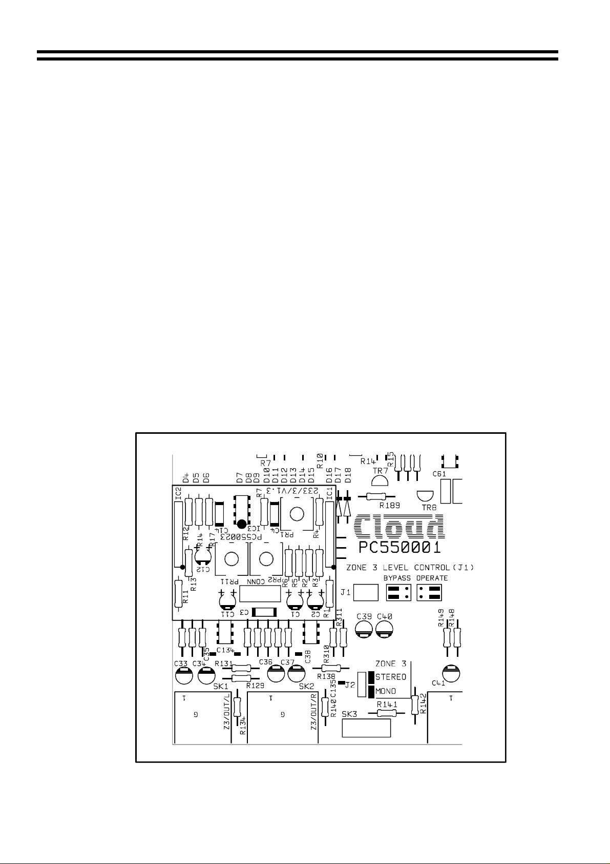
4.03 Stereo/Mono Operation
All CX233's leave the factory configured for stereo operation. By configuring circuit
jumpers on the upper PCB each output zone can be configured to operate in the mono
mode.
When operating in the mono mode, the output signal is present on both left and right
output connectors and either, or both may be used.
5 VCA Modules
5.01 VCA Modules
Local control of the signal level can be achieved on all three zone outputs by fitting
optional stereo VCA modules. These compact modules utilise a pair of industry standard
low distortion VCA's and simply plug into the upper PCB adjacent to the output circuitry.
The modules can be retro-fitted but the CX233 would normally be supplied with the
modules fitted if specified at the time of ordering.
NSTALLATION AND OPERATION MANUAL
5.02 Fitting VCA Modules
1. Before commencing any work, the CX233 must be disconnected from its power
source whether this be AC or DC.
2. Remove the CX233 top panel.
3. Locate the 10 pin male connector positioned adjacent to the respective output
zones. This should have each end pair of contacts shorted by single circuit
jumpers. Remove these two jump ers.
Page 6

CX233 I
NSTALLATION AND OPERATION MANUAL
4. Carefully position the VCA module on to the 10 pin connector making sure that
both rows of pins engage in the pcb mounted socket. This can be verified by
checking that the 3mm fixing hole perfectly aligns with the mounting spacer.
5. When you are satisfied that the VCA module is correctly fitted, secure the module
with the supplied M3 screw.
6. If you wish to bypass the respective front panel zone level control, the adjacent
jumpers can be configured as detailed on the PCB. This would remove the front
panel level control from the circuitry, leaving the remote level control to operate
independently.
7. Refit the top panel.
5.03 Remote Level Plate
A remote level plate complete with control is supplied with each VCA module, this can be
fitted directly onto a standard UK electrical single gang mounting box (recessed or
surface) with a minimum depth of 25mm (not supplied). 2 core screened cable must be
used to link the remote level control to the CX233.
5
When the remote level control facility is being used, it may be desirable to defeat the front
panel zone level control on the CX233 and this can be done by configuring an internal
jumper.
Remote level control wiring details
ZONE 1
OUTPUT
REMOTE
VOLUME
123
Left Right
123
NOTES
USE TWO CORE SCREENED CABLE CONNECT
SCREEN TO TERMINAL 1 ON BOTH UNITS
CONNECT TERMINAL 2 ON CX233 TO TERMINAL 2
ON THE CONTROL PLATE CONNECTOR
CONNECT TERMINAL 3 ON THE CX233 TO TERMINAL 3
ON THE CONTROL PLATE CONNECTOR
6 Optional DC Power Supply
6.01 Optional DC to DC Power Supply.
The DC supply kit is supplied with the following parts.
1 x NMXD 2415 DC to DC converter
2 x 1/4" PC mounting spade terminals
1 x PC mounting fuse holder
1 x 20x5mm T800mA Fuse
1 x 4 pin XLR connector with leads
2 x M3 fixing screws with nuts and washers
Page 7

6 CX233 I
6.02 Fitting of DC to DC power supply
1. Disconnect the CX233 from the mains power
2. Remove the top and bottom panels
3. Fit the two spade terminals on to the PCB. It is clearly marked Red+ve, Black-ve.
Then solder them in place
4. Fit the fuse holder to the PCB in the location marked F1. Solder this in place then
fit the T800mA fuse.
5. Fit the NMXD2415 to the pcb, then solder in place.
6 All the soldered joints should be cut flush with the joint.
7. Remove the cover positioned over the 4 pin XLR mounting hole.
8. Fit the 4 pin XLR connector using the screws provided. Connect the red and
black wires to the appropriate terminal on the PCB.
9. Re-fit the top and bottom panels.
7 Fire Alarm Interface (Remote Music Mute)
In certain circumstances, there may be a local authority or fire service requirement to
mute the music signals via a fire alarm control panel in an alarm condition. The CX233
provides a facility to attenuate or fully mute the music signals only, by using a fully floating
pair of contacts in the control panel which would need to be closed during an alarm
condition.
NSTALLATION AND OPERATION MANUAL
In the remote music mute mode both microphone signals are automatically routed to all
zone outputs bypassing any front panel switches, zone level controls and VCA controls.
In addition to this all music signals are attenuated by 20dB or muted, dependant on the
setting of the internal jumper.
It should be noted that in order to avoid a panic situation, the muting takes place
gradually, over approximately 10 seconds. The recovery is also subject to a similar
delay.
8 Mic 2 Emergency Mode
The Mic 2 input can be used for evacuation purposes by switching to the "emergency
mode". In this mode, the Mic 2 input would be muted when the CX233 is working
normally. When the fire alarm is activated, all music signals are muted/attenuated and
both Mic signals are routed to all outputs as above in section 7.10. In addition to this the
front panel level control for Mic 2 is rendered inoperative, instead a PCB mounted preset
controls the level of Mic 2. The rear panel gain control remains active under these
conditions. This emergency mode is intended to allow Mic 2 to be used for a dedicated
evacuation Mic or evacuation message player.
9Earthing
The 0v rail on the CX233 is connected to the mains earth and the mixer/zoner must
always be earthed. If any mains powered signal source has its own earth, then earth loop
hums may cause problems. The "hum" can be remedied in several ways. The preferred
method is to operate all inputs and outputs in the balanced mode, with the cable screen
only connected at the receiving end. Alternatively, re-route the mains supply of the
apparatus to the same point as that of the CX233. (Note: Microphone cables must be
earthed at both ends).
Page 8
CX233 I
NSTALLATION AND OPERATION MANUAL
10 Unbalanced Mode
If the zone outputs are required to operate in the unbalanced mode, it is suggested that
the unused pin of the XLR connector is not connected. The nominal output signal in this
mode is -6dBu and a small amount of extra gain may be required.
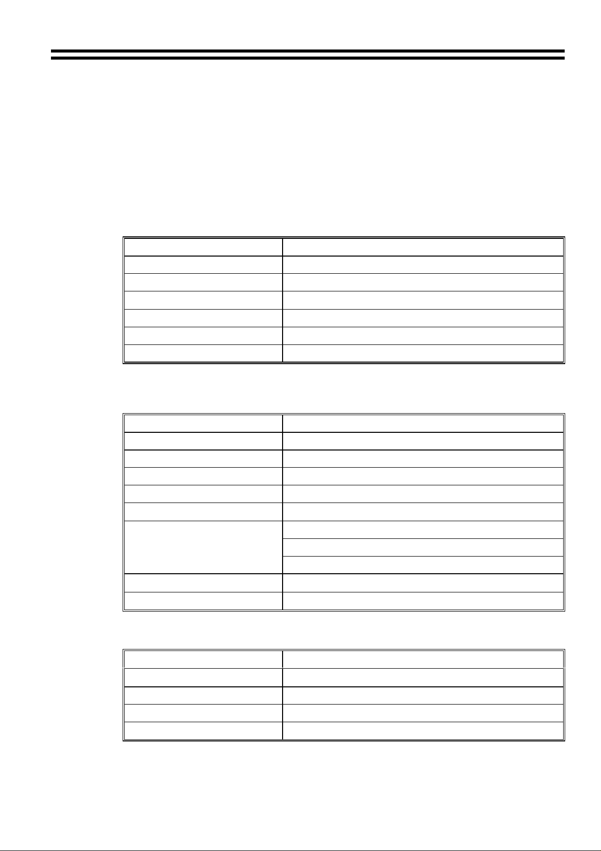
11 Technical Specifications
Music Channels
Frequency Response ±0.5db 20Hz/20kHz
Distortion <0.05% 20Hz/20kHz (+10dBu O/P)
Nominal Input Level 0dBu/775mV
7
Input Impedance
Headroom >20dB
Noise 0dB gain – 90dB CCIR – ARM
Input Gain Range ±12dB
20kΩ balanced 10kΩ unbalanced
Microphone Channels
Frequency Response ±0.5db 100Hz/20kHz -3db 30Hz
Distortion <0.03% 20Hz/20kHz (+10dBu O/P)
Maximum Gain 60dB
Gain Control Range 54dB
Headroom >20dB
Noise
Equalisation
Input Impedance
> - 128dB EIN 22Hz/22kHz (150Ω)
HF/High Frequency ±10dB 5kHz
LF/Low Frequency ñ10dB 100Hz
Contour +6dB at 3kHz
>2kΩ (balanced)
Common Mode Rejection >70dB 1kHz
Zone Outputs
Nominal Output Level 0dBu balanced , -6dBu unbalanced
Minimum Load Impedance
Equalisation HF/High Frequency ±10dB 10kHz
Maximum Output Level +26dbu balanced, +20dBu unbalanced
600
Ω
LF/Low Frequency ± 10dB 50Hz
Page 9

8 CX233 I
General Specifications
Power Consumption 25VA
Power Requirements 115V ± 5% or 230V ± 5%
NSTALLATION AND OPERATION MANUAL
Fuse Ratings
Width 482.6mm (rack)
Height 88.0mm (2U)
Depth 192.00mm
Weight 5.1Kgs
This product conforms to the following European Standards
EN 50081-1: 1992
EN 50082-1: 1992
EN 60065 : 1994
Power T250mA at 115V
Power T125mA at 230V
Battery T800mA (internal)
432.0mm (free standing)
SAFETY CONSIDERATIONS
CAUTION - MAINS FUSE
TO REDUCE THE RISK OF FIRE REPLACE THE MAINS FUSE ONLY WITH
THE SAME TYPE, WHICH MUST BE A CLASS 3, 240 VOLT, TIME DELAY
TYPE, RATED AT 125mA WHERE THE MAINS INPUT VOLTAGE IS SET TO
230 Volts ± 10% AC. FOR A MAINS VOLTAGE OF 115 Volts ± 10% AC. THE
FUSE SHOULD BE RATED AT 250mA
THE FUSE BODY SIZE IS 20mm x 5mm.
CAUTION - SERVICING
THIS UNIT CONTAINS NO USER SERVICEABLE PARTS. REFER ALL
SERVICING TO QUALIFIED SERVICE PERSONNEL. DO NOT PERFORM ANY
SERVICING UNLESS YOU ARE QUALIFIED TO DO SO.
WARNING
TO REDUCE THE RISK OF FIRE OR ELECTRIC SHOCK DO NOT EXPOSE
THIS EQUIPMENT TO RAIN OR MOISTURE.
15/11/99
 Loading...