

Page 1
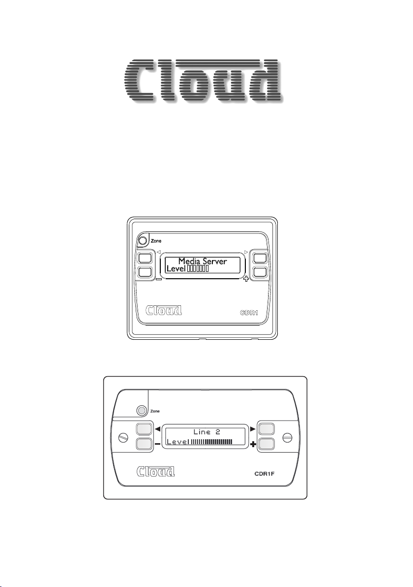
CDR-1 & CDR-1F
Remote Control Units
Installation Guide
Page 2

Page 3

Contents
Contents
Introduction ...................................................................4
Model types ............................................................................................... 4
What’s in the box .................................................................................... 5
CDR networks and terminations ......................................................... 5
Installation .....................................................................5
Cable length and DC power considerations ..................................... 8
Wiring ........................................................................................................ 9
Connecting and mounting – CDR-1 ..................................................10
Connecting and mounting – CDR-1F ...............................................13
Installer mode ......................................................................................... 15
Conguration .............................................................. 15
User mode ..............................................................................................16
Engineer mode .......................................................................................16
Default settings.......................................................................................17
Notes ........................................................................... 18
CDR‑1 & CDR‑1F Installation Guide v2.0 3
Page 4

Introduction
The CDR-1 & CDR-1F are remote control units specically designed for use with the
DCM-1/e. They may be tted to standard electrical back boxes in whatever location is
convenient in each zone.
Model types
The CDR-1 and CDR-1F are electrically and operationally identical, but differ in their
physical dimensions and mounting arrangements.
• The CDR-1 is a surface-mounting unit, which may be mounted via its supplied
mounting plate either to a single-gang back box, or directly to a suitable wall.
Max. projection from the wall is 30 mm.
• The CDR-1F is a ush-tting panel which ts to a standard dual-gang back box.
Max. projection from the wall is 10 mm.
Note: Where the term “CDR” is used in this manual, the text can be taken to apply to
both the CDR-1 and CDR-1F. In the section describing mounting (where the two types
differ), the full product names are used. An exception to this refers to the DCM-1/e’s
remote control ports, which are described as CDR-1 PORTS, to match the labeling
on the DCM-1/e itself.
A zone may have one CDR, more than one, or none at all. The DCM-1/e can support
up to 100 CDRs. CDRs are interconnected with standard CAT-5 UTP cable; units may
be daisy-chained at will and/or connected individually back to the DCM-1/e’s four
CDR-1 PORTS using almost any wiring topology convenient for the installation.
The CDR provides the user with the following local control functions for the zone in
which it is installed:
• Source selection
• Level control
• Group enable/disable (providing the zone has been dened as a group member)
• Local zone EQ adjustment (requires enabling on the DCM-1/e and entry of a key
code)
An Installer Mode permits zone assignment and adjustment of other installation
parameters.
CDR‑1 & CDR‑1F Installation Guide v2.04
Page 5

What’s in the box
As well as this manual, the shipping carton should contain the items listed below.
Please contact your Cloud dealer immediately if any of them are missing.
CDR-1 CDR1F
CDR-1 Remote Control panel CDR-1F Remote Control panel
Mounting plate 2x M3.5 panhead screws
2x M3.5 x 20 panhead screws 2-pin 5 mm–pitch screw terminal connector
2x M3 x 8 countersunk head screws
Installation
CDR networks and terminations
CDRs are connected to the DCM-1/e’s CDR-1 PORT sockets using standard
unscreened CAT-5 cable and RJ45 connectors. It may be possible to use pre-made
CAT-5 “patch cables” to connect any CDRs installed close to the DCM-1/e; otherwise
CAT-5 cable and crimp RJ45 plugs should be used.
Note: All CAT-5 cabling should be wired “pin-to-pin”; “crossed” or “null” cables will
not work.
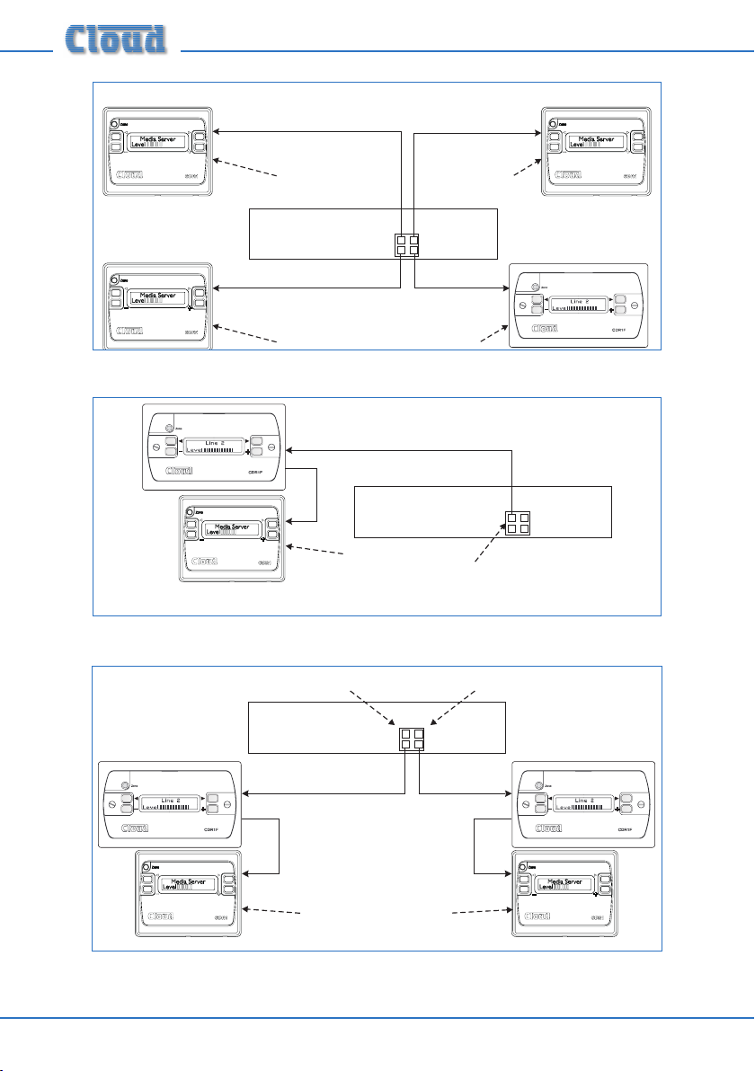
CDRs may be connected to the DCM-1/e either by wiring them directly and individually,
or by “daisy-chaining” them together. In most installations, a combination of these
methods is likely to be the most convenient solution from the point of view of practical
cabling. The diagrams on page 6 illustrate the types of wiring schemes that may be
employed; almost any variation on these is permissible.
Note that the two types of CDR may be intermixed freely as the installation requires.
CDR‑1 & CDR‑1F Installation Guide v2.0 5
Page 6
Termination ON TerminationON
(a)
IN
IN
Termination ON TerminationON
(b)
(c)
DCM-1/e
IN
IN
OUT
IN
Port Atermination ON
DCM-1/e
CDR-1PORTS
PORT
PORT
B
A
PORT
PORT
A
B
All DCM-1terminations are OFF
DCM-1/e
Termination ON
Allother terminations are OFF
CDR-1PORTS
PORT
PORT
B
A
PORT
PORT
A
B
IN
CDR-1PORT S
PORT
PORT
B
A
PORT
PORT
B
A
Port Atermination ON
PortBtermination ON
IN
OUT
IN
OUT
IN
All other terminations are OFF
IN
T
ermination ON
CDR‑1 & CDR‑1F Installation Guide v2.06
Page 7

Diag. (a) shows four CDRs, each connected to one DCM-1/e port; (b) shows a single
daisy-chain of two CDRs all on one port; c) shows two daisy-chains each of two CDRs
using two ports. Note that in the diagrams there is deliberately no indication as to
which zones any of the CDRs are in; this is because the system imposes no restriction
on their physical location. CDRs in different zones may be in the same “chain”, and
interconnections may be made purely on the basis of wiring convenience.
The CAT-5 wiring is essentially a data network, and as such, must be correctly
terminated. Both the DCM-1/e and CDR are provided with means of setting their
network terminations ON or OFF.
The rule governing terminations is:
• Devices (DCM-1/e or CDR) at the ends of a cable run must have their terminations
set ON.
• All intermediate devices must have their terminations set OFF.
• If both connectors on the same DCM-1/e CDR-1 PORT (either PORT A or
PORT B) are being used, the DCM-1/e may be considered as an intermediate
device, and its termination should be set to OFF*.
The correct termination setting is indicated for each device in the three wiring examples
illustrated on page 6. See Step 5 of “Connecting and Mounting – CDR-1” on page
page 11, or Step 3 of “Connecting and Mounting – CDR-1F” on page 14 for details
of how to set it.
*Please refer to the DCM-1/e Installation and User Guide, Section 4 (Appendix), for details of how
to set/unset the DCM-1/e’s CDR-1 PORT network terminations.
CDR‑1 & CDR‑1F Installation Guide v2.0 7
Page 8

Cable length and DC power considerations
The DCM-1/e’s internal PSU has sufcient capacity to power 8 CDRs (i.e., one per
zone) provided cable runs are not excessive and good quality cable and connectors
are used. If a system has more than 8 CDRs in total, one or more additional PSUs will
certainly be required. The probability of correct operation is a function of cable length,
cable and connector quality, the number of CDRs daisy-chained, and how many of them
are at a great distance from the DCM-1/e.
The maximum recommended cable length of the CDR network for reliable data
transmission is 1 km. This gure applies either to the total cable run between the
“farthest” CDR and the DCM-1/e if a single daisy-chain of CDRs has been employed
(as in (b) on page 6), or to the total run between the most remote CDRs if the
DCM-1/e is in the “middle” of the chain (as in illustration (a) on page 6). Cable runs
longer than this may work satisfactorily, but this cannot be guaranteed. Note that the
1 km gure is a maximum over which data may be reliably transmitted, not over which
a set of CDRs may be reliably powered. In all systems, it is the power distribution which
will limit maximum cable length, not the data.
If a CDR is found to operate unreliably, it should be powered independently from a
local PSU. The Cloud CPM-PSU is suitable for this purpose, and should be connected
to the EXT POWER socket at the rear of the CDR. In the case of the CDR-1, this is
a coaxial socket, mounted vertically on the PCB to the right (viewed from the rear).
See diag. on page 11. In the case of the CDR-1F, the EXT POWER socket is a 2-pin
5 mm-pitch screw terminal type connector below the RJ45 connectors; a mating male
connector is supplied with the unit. See diag. on page 13.
Note: Wiring convention of the external PSU is unimportant, as the CDR incorporates
a bridge rectier circuit which allows it to accommodate either polarity of connection.
Note that any further CDRs connected to the POWER OUT connector will be
powered by the external PSU.
If a third-party external PSU is to be used, it should be rated at either 12 – 24 V DC or
9 – 17 V AC. The current consumption of a CDR is 50 mA at 12 V.
CDR‑1 & CDR‑1F Installation Guide v2.08
Page 9

Wiring
1
8
Feed the installed CAT-5 cable(s) (or pre-made patch cable(s)) into the back box
on which the CDR is to be mounted. If not using pre-made cables, crimp the RJ45
connector(s) as per the pinout diagram below:
PIN USE CAT-5 CORE
1 n/u White + Orange
2 n/u Orange
3 n/u White + Green
4 DC +ve Blue
5 0v White + Blue
6 n/u Green
7 Data H White + Brown
8 Data L Brown
1
8
8
1
The connection at the DCM-1/e end is identical. Note that the CAT-5 interconnection
provides DC power as well as data, but also see the following chapters concerning
connecting and mounting the CDR-1 and CDR-1F.
CDR‑1 & CDR‑1F Installation Guide v2.0 9
Page 10

Connecting and mounting – CDR-1
The CDR-1 is designed for use with single-gang UK, US or Australian electrical back
boxes, using the mounting plate provided. It is also possible to mount it without a back
box directly onto a wall.
The mounting plate has several sets of xing holes to accommodate the different styles
of box. UK single-gang boxes are square, but note that if tting to a US or Australian
box, it should be tted with the long axis horizontal (‘landscape’ orientation), with the
screw holes to left and right.
1. Detach the mounting plate from the rear of the CDR-1 by removing the two
countersunk M3 screws. Retain the screws.
2. With back box: bring the CAT-5 cable(s) into the back box and pass through the
entry hole on the mounting plate. If a local external PSU is being used to power
the CDR-1, the DC feed from this should be fed through as well.
Without back box: simply pass the cables through the mounting plate entry
hole.
3. With back box: attach the mounting plate to the back box using the M3.5 screws
provided and the appropriate holes in the mounting plate (according to back box
type).
Without back box: x the mounting plate directly to the wall, using screws (not
supplied) of a length and type appropriate for the wall construction. Note that it
is important that only countersunk-headed screws are used, as a raised screw head
may foul the CDR-1’s internal PCB.
CDR‑1 & CDR‑1F Installation Guide v2.010
Page 11

4. Plug the cables into the CDR-1 sockets. The CAT-5 cable going to the mixer
(possibly via other CDRs) should be connected to the POWER IN socket. If other
CDRs are being installed further along the chain, the outgoing cable should be
connected to the POWER OUT socket. Ensure the RJ45 connectors fully latch
into place. If an external PSU is being used, plug it into the co-axial EXT POWER
socket.
CO-AXIAL SOCKET
FOR EXTERNAL PSU
J2 J1
ON
MID
OFF
END
TO NEXT
CDR-1
FROM
DCM-1
EXT POWER
POWER
OUT
POWER
IN
RJ45 SOCKETS FOR
DATA
INTERCONNECTION
5. Check that jumper J1 is in the OFF position. J2 should be set according to the
CDR-1’s position in the CAT-5 “chain”. If it is the nal (or only) panel in the chain
(i.e., nothing is plugged into the POWER OUT connector), set J2 to END; in all
other cases set it to MID. Carefully use tweezers or a pair of ne-nosed pliers for
this operation.
J2 J1
MID
END
ON
OFF
CDR‑1 & CDR‑1F Installation Guide v2.0 11
Page 12

6. Angle the CDR-1 so that the top is closer to the wall and push onto the mounting
plate such that the two small lugs on the inside of the top of the housing mate with
the corresponding anges on the plate.
7. Push the bottom of the CDR-1 towards the wall so that the two slots in the
bottom of the housing line up with the tapped holes in the bottom of the plate.
Mounting Plate
CDR-1
8. Screw the CDR-1 to the mounting plate using the two countersunk M3 screws
removed in step 1.
CDR‑1 & CDR‑1F Installation Guide v2.012
Page 13

Connecting and mounting – CDR-1F
The CDR-1F is intended for use with dual-gang UK size steel or PVC dry-lining back
boxes with an internal depth of 47 mm. As the internal electronic assembly is fully
screened, It can also be mounted without a back box directly into a suitable wall cavity.
Refer to page 14 for CDR-1F dimensions
In order for the display to be readily legible, only “landscape” orientation should be
employed.
1. With back box: bring the CAT-5 cable(s) into the back box. If a local external
PSU is being used to power the CDR-1F, the feed from this should be fed through
as well.
Without back box: simply feed the cables up through the hole in the wall.
2. Plug the cables into the CDR-1F sockets. The CAT-5 cable going to the mixer
(possibly via other CDRs) should be connected to the POWER IN socket. If other
CDRs are being installed further along the chain, the outgoing cable should be
connected to the POWER OUT socket. Ensure the RJ45 connectors fully latch
into place. If an external PSU is being used, plug it into the 2-pin EXT POWER
socket.
RJ45 SOCKETS FOR
DATA
INTERCONNECTION
TO NEXT CDR
FROM DCM-1/e
2-PIN EXTERNAL
POWER SOCKET
CDR‑1 & CDR‑1F Installation Guide v2.0 13
Page 14

3. Check that jumper J1 is in the OFF position. J2 should be set according to the
CDR1F’s position in the CAT-5 “chain”. If it is the nal (or only) panel in the chain
(i.e., nothing is plugged into the POWER OUT connector), set J2 to END; in all
other cases set it to MID. Carefully use tweezers or a pair of ne-nosed pliers for
this operation.
J1 Settings
End of chain Middle of chain
MIDENDOFF
ON
MIDENDOFF
ON
4. With back box: carefully position the rear metal screening box of the CDR-1F
into the back box, taking care that the CAT-5 cable(s) and PSU wiring (if used) are
not under any strain. Insert the two M3.5 raised-head screws supplied through
the xing holes in the front plate and engage them in the threaded inserts or lugs
of the back box. Tighten until the panel is neatly ush against the wall – do NOT
over-tighten.
Without back box: carefully position the rear of the unit in the hole, and x the
front panel with screws of a type and length appropriate to the wall construction.
No. 6 woodscrews are satisfactory provided that timber battens are available
either side of the hole.
CDR-1F Dimensions
CDR‑1 & CDR‑1F Installation Guide v2.014
Page 15

Conguration
Each CDR must be assigned to a zone; this will normally be the zone in which it is
physically located. As shipped from the factory, a CDR has no zone assigned, and when
powered for the rst time it will rst display the backlight/contrast adjust screen, and
then prompt for a zone assignment before continuing, as shown below:
Use the + and – keys to scroll to the zone required, unless Zone 1 is correct. Press the
ZONE button to accept the assignment (the display changes to the Set Key screen);
after a few seconds, the CDR will enter normal User Mode, with the zone assignment
conrmed.
If it is necessary to change the zone assignment at a later date for any reason, this can
be done by putting the CDR into Installer Mode (see below).
Installer mode
To put the CDR in Installer Mode:
• Remove the CDR from its back box or mounting position by removing the two M3
screws at the bottom of the housing in the case of the CDR-1, or by removing the
two front xing screws in the case of the CDR-1F. Retain the screws.
• Remove power from the CDR, either by powering the system down or removing
the POWER IN connector.
• Move jumper J1 from OFF to ON
• Reapply the power
CDR‑1 & CDR‑1F Installation Guide v2.0 15
Page 16

Installer mode allows access to the following unit-specic settings:
• Backlight and contrast adjustment
• Inactivity time
• Zone assignment
• Set Engineer key
Each of the above settings can be accessed in turn by pressing the ZONE button.
A full description of Installer Mode can be found in the DCM-1/e Installation and
User Guide, Section 3 (Conguration).
To return the CDR to normal operation:
• Remove power from the CDR.
• Move jumper J1 from ON to OFF
• Reapply the power
• Ret the remote control to its mounting plate with the two M3 screws (CDR-1)
or to its back box/mounting hole with the front panel xing screws (CDR-1F).
User mode
The CDR’s normal operating state is User Mode, which permits selection of music
source, level adjustment, and Group enabling/disabling (if available).
User Mode is fully described in the DCM-1/e Installation and User Guide,
Section 3 (Conguration).
Engineer mode
The CDR can be used to adjust the EQ in a zone from within the zone itself by putting
it in Engineer Mode. Engineer Mode must rst be enabled from the DCM-1/e, and then
a “password” key code entered on the CDR. The default key is listed below. The key can
be changed in Installer Mode.
A full description of Engineer Mode, and how to enable it can be found in the
DCM-1/e Installation and User Guide, Section 3 (Conguration).
CDR‑1 & CDR‑1F Installation Guide v2.016
Page 17

Default settings
J1= OFF
J2 = END
KEY = “<<>>”
Should you have any questions concerning the installation and connection of the
CDR-1/CDR-1F please contact our Technical Support staff (details on rear cover).
CDR‑1 & CDR‑1F Installation Guide v2.0 17
Page 18

Notes
CDR‑1 & CDR‑1F Installation Guide v2.018
Page 19

CDR‑1 & CDR‑1F Installation Guide v2.0 19
Page 20

Cloud Electronics Limited
140 Staniforth Road, Shefeld. S9 3HF. England
Tel: +44 (0)114 244 7051 Fax: +44 (0)114 242 5462
E-mail: info@cloud.co.uk Web: www.cloud.co.uk
Cloud Electronics USA
2065 Sidewinder Drive, Suite 200, Park City
Utah 84060. United States of America.
Toll Free: 0855 810 0161
E-mail: sales@cloudusa.pro Web: www.cloudusa.pro
 Loading...