

Page 1
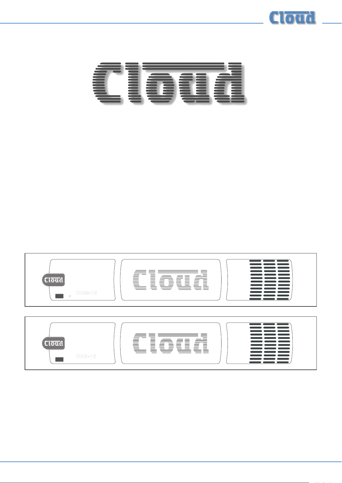
CAM-16
Audio Distribution Matrix
CAS-16
Audio Distribution Sub-Station
POWER
MUTE
CCAAMM--1166
Audio Distribution Matrix
POWER
CCAASS--1166
Audio Distribution Sub-Station
Installation and User Guide
CAM-16 / CAS-16 User Manual v1.0 1
Page 2
Important Safety Instructions
WARNING:
To reduce the risk of re or electric shock, do not expose this appliance to rain or moisture.
CAUTION:
Use of controls or adjustments or performance of procedures other than those specied may result in hazardous radiation
exposure.
CAUTION
RISK OF ELECTRIC SHOCK
DO NOT OPEN
WARNING: SHOCK HAZARD - DO NOT OPEN
AVIS: RISQUE DE CHOC ÉLECTRIQUE - NE PAS OUVRIR
The lightning ash with the arrowhead symbol within an equilateral triangle, is intended to alert you to the presence of
uninsulated dangerous voltages within the product’s enclosure that may be of sufcient magnitude to constitute a risk
of electric shock.
The exclamation point within an equilateral triangle is intended to alert the user to the presence of important
operating and maintenance (servicing) instructions in the literature accompanying the appliance.
1. Read these instructions.
2. Keep these instructions.
3. Heed all warnings.
4. Follow all instructions.
5. Clean only with dry cloth.
6. Do not use this apparatus near water.
7. Do not install near any heat sources such as radiators, heat registers, stoves, or other apparatus (including ampliers) that
produce heat.
8. Do not defeat the safety purpose of the polarized or grounding-type plug. A polarized plug has two blades with one wider
than the other. A grounding type plug has two blades and a third grounding prong. The wide blade or the third prong are
provided for your safety. If the provided plug does not t into your outlet, consult an electrician for replacement of the
obsolete outlet.
9. Protect the power cord from being walked on or pinched particularly at plugs, convenience receptacles, and the point
where they exit from the apparatus.
10. Only use attachments/accessories specied by the manufacturer.
11. Use only with the cart, stand, tripod, bracket, or table specied by the manufacturer, or sold with the apparatus. When a
cart is used, use caution when moving the cart/apparatus combination to avoid injury from tip-over.
12. Unplug this apparatus during lightning storms or when unused for long periods of time.
13. Refer all servicing to qualied service personnel. Servicing is required when the apparatus has been damaged in any way,
such as power-supply cord or plug is damaged, liquid has been spilled or objects have fallen into the apparatus, the apparatus
has been exposed to rain or moisture, does not operate normally, or has been dropped.
14. No naked ames, such as lighted candles, should be placed on the apparatus.
WARNING: Excessive sound pressure levels from earphones and headphones can cause hearing loss.
CAM-16 / CAS-16 User Manual v1.02
Page 3

Contents
Important Safety Instructions ..................... 2
Safety Information ........................................ 4
Safety notes regarding installation .......................... 4
Conformities ............................................................... 4
Power supply information ........................................ 4
CAUTION – Servicing ............................................. 4
General Description ...................................... 5
CAM-16 and CAS-16 main features ......................5
Applicable Models: ..................................................... 5
What’s in the Box ...................................................... 5
Block Diagrams ..........................................................6
Front panel descriptions...........................................7
Rear panel descriptions ............................................ 7
Installation ..................................................... 8
Mechanical ................................................................... 8
Connections and adjustments .................................8
Power supply ...........................................................8
Line inputs ................................................................ 8
Global input .............................................................8
Outputs 1 to 16 ...................................................... 9
Balanced Line Output
(CAM-16 Output 16 only) ...................................9
Remote Music Mute ...............................................9
The CAS-16 Sub-Station .......................................... 9
Connecting the CAS-16 ...................................... 10
Outputs ...................................................................10
Chassis Ground Terminal .......................................10
Appendix ...................................................... 10
EMC considerations ................................................10
Earthing ......................................................................10
Technical Specications ..........................................11
CAM-16 / CAS-16 User Manual v1.0 3
Page 4

Safety Information
Safety notes regarding installation
• Do not expose this unit to water or moisture
• Do not expose the unit to naked ames.
• Do not block or restrict any air vent
• Do not operate the unit in ambient temperatures above
45°C
• The unit has no internal user adjustable parts. Do not
remove any panel.
• Refer any servicing to qualied service personnel.
• Do not replace the power transformer with any other
type
Conformities
The Cloud CAM-16 and CAS-16 conform to the following
European EMC Standards:
BS EN 55103-1:2009
BS EN 55103-2:2009
These products have been tested for normal use in
the commercial and light industrial environment. If the
equipment is used in controlled EMC environments, the
urban outdoors, heavy industrial environments or close
to railways, transmitters, overhead power lines etc., the
performance of the units may be degraded.
Power supply information
The CAM-16 and CAS-16 are each shipped with a 15 V AC,
1.25 A transformer. When powering the CAM-16 and CAS16, please ensure that your local AC supply is within the
range of voltages required by the adaptor BEFORE you plug
it into the mains. We strongly recommend that you only use
the supplied transformer.
When the power switches are in the off (‘O’) position, the
CAM-16 and CAS-16 are disconnected from the power
transformers.
CAUTION – Servicing
The unit contains no user serviceable parts. Refer servicing
to qualied service personnel. Do not perform servicing
unless you are qualied to do so. Disconnect the power
cable from the unit before removing the top or bottom
panel. Only reassemble the unit using bolts/screws identical
to the original parts.
The Cloud CAM-16 and CAS-16 conform to the following
European electrical safety standard:
BS EN 60065:2002
The power transformers for the Cloud CAM-16 and
CAS-16 conform to the following standards:
Power transformer for the UK market:
BS EN60742 + BABT
Power transformer for the European market:
EN60742 + EN60950
Power transformer for USA and Canada:
C-UL Approved
CAM-16 / CAS-16 User Manual v1.04
Page 5

General Description
The Cloud CAM-16 is a headphone distribution matrix
designed to provide headphone monitoring of up to eight
stereo sound sources at up to sixteen remote locations. The
CAM-16 has eight stereo line inputs and a balanced ‘global’
input with priority. A remote music mute facility is also
provided, that may be used to satisfy the requirements of the
Local Fire Ofcer.
Up to 16 RH-8 or WP-8 remote headphone stations can be
connected to the CAM-16. Both are tted with a headphone
socket, rotary source selection switch and volume control.
The RH-8 is a small, self-contained unit intended to be
tted to the framework of an exercise machine or to a at
surface. The WP-8 is a wall-mounting panel version, and
ts a standard single-gang electrical back box, either ush
or surface-mounting. The WP-8 also has the provision for
connecting loudspeakers, Each headphone station is wired to
one output of the CAM-16 using standard CAT-5 cable and
RJ-45 connectors.
The CAS-16 Sub-Station provides the capacity for another
sixteen RH-8 or WP-8 headphone stations. The CAM-16
can drive up to 15 CAS-16 units, allowing a maximum of
256 outputs. The CAM-16 and the sub-stations are ‘daisychained’ together, a multi-core cable being supplied with
each unit for this purpose.
The only front panel control on either unit is the power
switch. All input and output connectivity and gain controls
are on the rear panels. The units are intended to be rackmounted in a protected area, with only the headphone
stations available to the users.
CAM-16 and CAS-16 main features
CAM-16:
• Stereo audio matrix with eight line inputs
• Outputs for sixteen headphone stations
• Global input with priority override
• Short-to-ground access port for global input
• Gain controls for all inputs
• LED signal level indicators for easy balancing of line
inputs
• Output 16 also available as a balanced mono feed
• Music Mute control input for interface with emergency
systems
• Connects to headphone stations via CAT-5 cable and
RJ-45 connectors
• No front panel controls except power switch
CAS-16:
• Expansion unit for CAM-16
• Outputs for sixteen headphone stations
• No front panel controls except power switch
Applicable Models:
This manual describes the installation, wiring and set-up
procedures for the CAM-16 Audio Distribution Matrix and
the CAS-16 Sub-Station. Both the CAM-16 and CAS-16
require RH-8 and/or WP-8 headphone stations to realise
a functional system; installation instructions for these are
included with each headphone station.
What’s in the Box
Please check the shipping carton for damage before opening.
If there is damage, please contact your Cloud agent and
the shippers.
The packing carton should contain the following items:
• CAM-16 or CAS-16 unit
• AC mains adaptor (transformer)
• Set of mating plug-in screw-terminal connectors (CAM-
16 only)
• 25-pin Dsub multicore expansion cable, 350 mm, male-
to-female (CAS-16 only)
• This manual
CAM-16 / CAS-16 User Manual v1.0 5
Page 6

Block Diagrams
CAM-16 / CAS-16 User Manual v1.06
Page 7

Front panel descriptions
POWER
CCAASS--1166
Audio Distribution Sub-Station
1 2
1. Power switch with integral LED
2. Ventilation grille
Rear panel descriptions
CAM-16
3
5 714
EXPANSION LINK
TO SUB-STATION CAS-16
4 13 16
12
1415
PUSH
8 9 10 116
CAS-16
Audio Distribution Sub-Station
CAS-16
12
3. LINE 1 to LINE 8 – stereo line inputs for music sources (phono sockets)*
4. GAIN 1 to GAIN 8 – level trims for each line input*
5. SIGNAL 1 to SIGNAL 8 - LEDs to aid gain setting of line inputs*
6. GLOBAL INPUT – mic or line level input routes to all outputs with priority*
7. GAIN – Global Input gain adjustment*
8. FILTER – in/out switch for hi-pass lter (200 Hz) in Global Input signal path*
9. ACCESS – short pins together to enable Global Input*
10. REMOTE MUSIC MUTE – short pins together to mute all music sources*
11. Earth (Ground) binding post*
12. OUTPUT 1 to OUTPUT 16 – RJ45 sockets for connection of headphone stations
13. CH16 MONO LINE OUT – balanced mono output for external amplier and speakers*
14. EXPANSION LINK OUTPUT – daisy-chain output to rst (or next) CAS-16
15. EXPANSION LINK INPUT – daisy-chain input from CAM-16 (or previous CAS-16)**
16. POWER INPUT – connects to supplied AC mains transformer
16
* these items only tted to CAM-16 ** this item only tted to CAS-16
CAM-16 / CAS-16 User Manual v1.0 7
Page 8

Installation
Mechanical
Both the CAM-16 and CAS-16 are suitable for mounting in
a standard 19” equipment rack. Each occupies two units of
rack space (2U). The units are 170 mm deep, but the rack
should have at least 235 mm of depth available to permit
clearance of the rear panel connectors. Wherever possible,
avoid positioning the units in close proximity to strong
magnetic elds or equipment which may operate at a high
temperature (e.g., high-power ampliers).
The CAM-16 and CAS-16 are both convection-cooled
and generate no signicant heat. Apart from observing the
guideline above (re hot-running equipment), no special
provision for ventilation need be made. However, note
that it is good practice not to enclose any rack containing
electronic equipment in an enclosed or sealed space, such as
a cupboard.
Connections and adjustments
Power supply
Both the CAM-16 and CAS-16 operate from external
in-line transformers, which are supplied with each unit.
The transformer outputs are in the form of a ying lead
terminated with a 2.2 mm coaxial connector. Plug this into
the POWER INPUT socket 16 on the rear of the unit. Plug
the transformers into a suitably positioned AC power socket
within the rack.
Only use the in-line transformers supplied with the units.
Only use one transformer per unit – do not attempt to wire
multiple units to a single transformer.
Line inputs
The CAM-16 has eight stereo line inputs; these are suitable
for most music sources such as CD and DVD players, TV
receivers, MP3 players, music servers, etc. All the inputs are
unbalanced and use phono (RCA) sockets 3. The input
impedance is 47k ohms. If possible, install the music sources
in the same rack so that the length of the connecting cables
is as short as possible.
Sensitivity and gain adjustments
Each line input has a preset gain control 4 on the rear
panel, adjacent to the respective input. The input sensitivity
can be varied from –14 dBu (155 mV) to +6 dBu (1.55 V).
The gain of each input should be set using the SIGNAL
LED 5. With the music sources playing, increase the gain
control from the fully anti-clockwise position until the LED
illuminates briey on signal peaks. Repeat this process for
the other inputs in use. This process ensures that all the
inputs are at roughly the same level in the matrix, and there
will be no irritating change in headphone volume when
switching between sources. Do not increase the gain further
as this may result in a distorted signal when the RH-8 or
WP-8 volume control is set to maximum.
Global input
A ‘global’ microphone/line input is provided to permit
system-wide paging, announcements or emergency messages.
The global signal is routed to all headphone ampliers with
automatic priority over the music signal.
The input stage is electronically-balanced, and congured
for optimum noise performance. The global signal is mixed
into the signal path before the volume control stage,
so that announcements are heard at the user-set level.
The input impedance is 5k ohms and is suitable for 600
ohm microphones and general line level signals. The input
connector is a standard XLR3F, located on the rear panel 6.
The global input is compatible with general purpose paging
microphones tted with a ‘push-to-talk’ switch, or opencollector ‘mic active’ output, which should be connected
to the Access Input 9. To enable the global input, the two
pins of the Access Input should be shorted together. If the
input is to be used for purposes other than paging, it will
be necessary to permanently link pins 1 and 2 on the 4-way
screw-terminal connector to make the input continuously
active. (Note that pins 3 and 4 of this connector are
concerned with the separate Remote Music Mute function –
see “Remote Music Mute” on page 9).
WIRING THE GLOBAL OUTPUT
BALANCED
2 1
3
GROUND (SCREEN)
REV-PHASE (-)
IN PHASE (+)
UNBALANCED
2 1
3
GROUND (SCREEN)
NO CONNECTION TO PIN 3
HOT (+)
The global input can be used for both microphone and line signals
Use the high pass filter for improved speech clarity
Note that if feeding the global input from an unbalanced
source, pins 1 and 3 should be linked on the mating XLR
plug as shown above.
Gain control
A gain control of the preset type 7 is located next to the
input socket. The gain range is 0 to 50 dB. This range allows
direct connection of both microphones and units with line
level outputs (such as radio mic receivers) without the
need for additional attenuation. A high overload margin is
maintained at all gain settings.
Hi-pass lter
A switchable high-pass lter 8 is provided for the global
input; this can help improve speech intelligibility with paging
mics by attenuating breath blasts and low frequency handling
noise. The lter has a -3 dB frequency of 200 Hz and a slope
of 18 dB/octave. If the global input is used for music, the
lter should be switched ‘out’.
ACCESS
CONTACT
1234
CLOSE CONTACT
TO OPEN
GLOBAL INPUT
CAM-16 / CAS-16 User Manual v1.08
Page 9

Priority
The global input includes an automatic priority circuit to
ensure that it always has priority over all music sources.
When a signal is detected at the global input, all music signals
are attenuated by approximately 30 dB; once the global input
stops, the music levels smoothly restore to their former
levels.
Outputs 1 to 16
RH-8 and/or WP-8 headphone stations should be connected
as required to Outputs 1 to 16 12, using standard IT
industry CAT-5 UTP cable and RJ45 connectors. Pre-made
CAT-5 patch cables may be used if they are available in
adequate lengths. Otherwise, use unterminated CAT-5 cable,
and wire the RJ-45 plugs as shown below:
The WP-8’s volume control and source selector can then be
used to control the signal fed to the external system. Do not
plug headphones into a WP-8 being used for this purpose.
The nominal output level is 0 dBu (775 mV). To connect to
a balanced input (typically a professional amplier with XLR
inputs), use 2-core screened cable. Single-core screened
cable may be used if connecting to an unbalanced input
(typically a ‘hi-’ amplier with phono sockets). Wire the
output connector as shown below.
WIRING THE MONO LINE OUTPUT
BALANCED UNBALANCED
-
0V +
COLD (+)
HOT (+)
(CHANNEL 16 ONLY)
HOT (+)
0V +
-
PIN CAT-5 CORE
1 White + Orange
2 Orange
3 White + Green
4 Blue
5 White + Blue
6 Green
7 White + Brown
8 Brown
The total cable length from a headphone station to the
CAM-16 should not exceed 100 m (328 ft).
See the Installation Guides supplied with the RH-8 and/
or WP-8 headphone stations for additional connection
information.
Balanced Line Output
(CAM-16 Output 16 only)
A mono sum of the signal at Output 16 of the CAM-16 is
available as a balanced line level output on a 3-pin 5 mmpitch screw terminal connector 13.
This may be used to provide a signal for a separate sound
system using an external amplier and loudspeakers. A
headphone station will still need to be connected to Output
16, and we recommend that a WP-8 is wall mounted in a
convenient location in the area covered by the loudspeakers.
GROUND
(SCREEN)
GROUND
(SCREEN)
Remote Music Mute
In public and commercial premises, it is often necessary to
ensure that any background music – via either speakers or
headphones – is muted when an emergency arises. In most
territories, the Local Authority or Fire Service make this
a legal requirement. The Remote Music Mute input on the
CAM-16 allows an external system (typically BMS or Fire
Control) to mute all music signals throughout the whole
system.
The input uses pins 3 and 4 of the 4-pin 5 mm-pitch screwterminal connector 10; these pins should be connected to a
set of NO (Normally Open) relay contacts in the external
system. (Note that pins 1 and 2 of this connector are
concerned with the separate Global Input Access function –
see “Global input” on page 8).The two-wire connection
should not be connected to any other circuit or voltage. In
many cases, the re alarm installation company will provide
an auxiliary relay located close to the sound equipment rack.
The global input continues to operate normally when the
music mute is active, to permit evacuation announcements
to be made.
The CAS-16 Sub-Station
If the system being installed requires more than 16
headphone stations, one or more CAS-16 Audio
Distribution Sub-Stations will be needed. Each CAS-16
provides 16 further outputs, and up to 15 CAS-16s may
be connected, giving a maximum system capability of 256
headphone stations.
CAS-16s should always be tted in the same rack as the
CAM-16 forming the system’s base unit. See note below
regarding interconnecting cables.
The CAS-16 has no controls other than the front panel
power on/off switch. Like the CAM-16, each unit is supplied
with an external in-line type mains transformer, and only this
transformer should be used.
CAM-16 / CAS-16 User Manual v1.0 9
Page 10

Connecting the CAS-16
Each CAS-16 is shipped with a multicore cable terminated
with 25-pin Dsub connectors, male-to-female. Plug the male
connector into the Expansion Link Output 14 on the rear
panel of the CAM-16, and the female connector into the
Expansion Link Input 15 on the rear of the CAS-16. Tighten
all the locking screws.
If the system needs more than one CAS-16 (i.e., more than
32 headphone stations are required), simply “daisy-chain” the
additional CAS-16(s) in the same manner, by connecting the
Expansion Link Output of one to the Expansion Link Input
of the next, using the multicore cables provided in each case.
PUSH
EXPANSION LINK
TO SUB-STATION CAS-16
CAM-16
CAS-16
CAS-16 #1
CAS-16 #2
Audio Distribution Sub-Station
CAS-16
Audio Distribution Sub-Station
TO FURTHER CAS-16s
Appendix
EMC considerations
The CAM-16 Audio Distribution Matrix and CAS-16 Audio
Distribution Sub-Station fully conform to the relevant
electromagnetic compatibility (EMC) standards and are
technically well behaved. You should experience no problems
interfacing units to other items of equipment and under
normal circumstances, no special precautions need to
be taken. If the unit is to be used in close proximity to
potential sources of HF disturbance such as high power
communication transmitters, radar stations and the like, it is
suggested that input signal leads be kept as short as possible.
If the CAM-16 is mounted in a 19” rack, do not locate the
unit in close proximity to a powerful amplier of any kind,
which may radiate a strong magnetic eld from the power
transformer.
Earthing
When several mains powered units are connected together
via their signal cables, there is a risk of one or more earth
loops, which may cause an audible hum on the system
even with the gain controls set to minimum. The 0 V rail
of a CAM-16 is directly coupled to the chassis ground. No
interconnection problems should be encountered, but if
there is any hum or other extraneous noise when source
equipment is connected, the situation can generally be
remedied by observing the following guidelines:
Only the multicore cable supplied with each CAS-16 should
be used for interconnecting a CAM-16 and a CAS-16, or
two CAS-16s. Do not attempt to locate a CAS-16 remotely
from its CAM-16 base unit, or from other CAS-16s in the
system, by the use of a longer cable.
Outputs
Each of the CAS-16’s outputs is identical to the headphone
outputs on the CAM-16, and may be wired to headphone
stations in exactly the same way. See “Outputs 1 to 16” on
page 9, and also refer to the manuals supplied with the
RH-8 and WP-8 headphone stations.
Chassis Ground Terminal
The rear panel of the CAM-16 is tted with an Earth (Ground)
binding post 11. This is provided for protection purposes; the
CAM-16 will normally be connected to a number of different
consumer-type sources - TV sets, radio receivers, satellite
receivers, etc., and grounding the CAM-16 is a safety measure
to protect the users of the system. The terminal should be
connected to a convenient earth point in the rack’s mains
distribution system.
• Always connect sources using balanced connections
wherever possible. Note that, for EMC reasons, the
cable screen should be connected at both ends.
• Use audio isolating transformers (readily available from
trade suppliers) at the inputs if necessary. These will
ensure that the amplier is electrically isolated from the
source equipment.
• The signal source units should be located as close
as possible to the CAM-16 and the metal housing of
the various units should not be electrically connected
together through the equipment rack. If this is a
problem, rack isolating kits are available from specialist
hardware suppliers. If the problem persists, try to
connect all interconnected units, including power
ampliers to a common power source to ensure a
common ground is provided.
CAM-16 / CAS-16 User Manual v1.010
Page 11

Technical Specications
CAM-16 CAS-16
Line Inputs
Global Input
Frequency response
Input level
Input impedance 47k ohms
Input gain range 20 dB
Input level indicator
Input connector 2 x RCA phono jack (stereo)
Frequency response
High pass lter
Gain range 0 dB to 50 dB
Input impedance 5k ohms
CMR >70 dB @ 1 kHz
Access contact
20 Hz – 20 kHz ±0.5 dB
-14 dBu (155 mV) to
+6 dBu (1.55 V)
LED – illuminates above a
xed threshold
20 Hz – 20 kHz ±1 dB
-3 dB @ 200 Hz – 18 dB/oct
(with in/out switch)
Channel off/on by closing
contact
Line Output
Channel 16
Headphone Output
via RH-8 or WP-8
Speaker Output
via WP-8
Other
PSU
Nominal output level 0 dBu (775 mV)
Minimum load 600 ohms
Nominal output level 100 mW per channel with 32 ohm load
Optimum load impedance 32 ohms
Recommended headphones Cloud CP32
Nominal output level 150 mW per channel with 8 ohm load
Optimum load impedance >8 ohms
Power consumption
Width 482.6 mm (19.0”)
Height 88.0 mm (3.50”) – 2U
Depth 170.0 mm (6.70”) + connectors
Weight 4.0 kg net 3.3 kg
Output 15 V AC 1.25 A 18.5 VA
Weight 0.52 kg net
25 VA with approved external
transformer
20 VA with approved external
transformer
CAM-16 / CAS-16 User Manual v1.0 11
Page 12

Cloud Electronics Limited
140 Staniforth Road
Shefeld S9 3HF
England
Tel: +44 (0)114 244 7051
Fax: +44 (0)114 242 5462
email: info@cloud.co.uk
web: www.cloud.co.uk
 Loading...