

Page 1

AE-1
Installation & User Guide
V 6.0
Cloud Electronics Limited
140 Staniforth Road, Sheffield, S9 3HF England
Tel +44 (0) 114 244 7051
Fax +44 (0) 114 242 5462
E-mail
info@cloud.co.uk
Web site http://www.cloud.co.uk
Page 2

AE-1:
Installation & User Guide 1
08-07-02 V6
AE-1
Installation & User Guide
Contents
Section
Page
1 Safety Notes.............................................................................2
2 General ..................................................................................... 2
3 AE-1A........................................................................................2
4 Schematic Block Diagram.......................................................2
5 Installing an AE-1..................................................................... 3
5a Hardware and Wiring Requirements.......................................... 3
5b Connecting an AE-1................................................................... 3
5c Configuring a Z4 or Z8 to an AE-1 .............................................3
5d Configuring an MPA-626 to an AE-1..........................................4
6 Music Inputs............................................................................. 4
7 Music Level Control................................................................. 4
8 Microphone Inputs................................................................... 4
9 Microphone Level Control....................................................... 4
10 System Music Mute ................................................................. 4
11 Music Ducking .........................................................................4
12 Installing Two AE-1’s to a Single Facility Input ....................5
12a Configuring a Z4 or Z8 to an AE-1 .............................................5
12b Configuring an MPA-626 to an AE-1..........................................5
13 Solving Problems: Ground Loops & Hum.............................5
14 Solving Problems: EMC Considerations ............................... 6
Page 3
2
AE-1:
Installation & User Guide
08-07-02 V6
1 Safety Notes
The Cloud AE-1 Remote Input Module must be fitted by a technically qualified person. Do not
tamper with any part of the equipment unless you are qualified to do so.
Before working on any piece of Cloud equipment turn the power off and remove the mains
supply cable from the rear of the unit
2 General
The Cloud AE-1 is an active module with facilities for both line level and unbalanced
microphone inputs.
The AE-1 is compatible with all Cloud Z4 & Z8 mixers as well as the MPA-626 amplifier, and
can be used for any application where local connection of a microphone and/or a music source
signals is required. The prime application is the fitness suite where the aerobics instructor is
required to connect their music source and/or radio microphone directly into the house system.
In addition to the separate level controls for music and microphone signals, the user can select
‘music ducking’ to attenuate the music signals when the microphone is used and ‘system music
mute’ to mute the background music. Both ‘system music mute’ and ‘music ducking’ are tamper
proof and will operate only when a signal is detected within the AE-1.
3 AE-1A
The AE-1A is available for the American market. It has identical operation to the AE-1 but has
been designed to fit a 1.5” deep US three-gang box. The front panel dimensions of the AE-1A
are 4.5” × 6.38”.
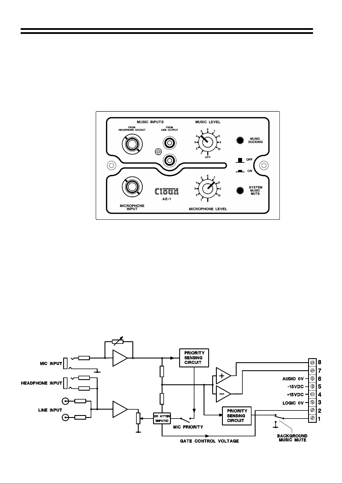
4 Block Diagram
Page 4

AE-1:
Installation & User Guide 3
08-07-02 V6
5 Installing an AE-1 Active Module
5a Hardware and Wiring Requirements
The Cloud AE-1 active module is the same physical size as a double UK electrical socket (13A
Type) and can be mounted in the recessed back box provided or be surface mounted in a
standard 35mm deep housing. The AE-1 should be connected to the facility input of the host
mixer or amplifier using 8-Core cable with an overall screen. The AE-1 terminations are
conventional screw terminals while the facility input on the host unit is a 9-Pin sub-D type
connector (sub D-Type connector is supplied with the unit).
It is advised that you are vigilant when wiring the AE-1 as wiring conventions between old and
new host units do vary. Since the AE-1 derives its power from the host unit, certain wiring
errors can cause power supply problems resulting in temporary shutdown of the host mixer or
amplifier; the unit can be reset by switching it off for 30 seconds. If a problem such as this is
experienced, disconnect the facility connector and double check the wiring against the diagram,
also note that we recommend a maximum cable length of 100m (328ft).
5b Connecting an AE-1
5c Configuring a Z4 or Z8 to an AE-1 Location of Jumper J4
Should you wish the mic signals from the mixer to
override the AE-1 signals, set Jumper ‘J4’ on the zone
board to the ‘ON’ position.
When setting the jumper(s) please ensure that you:
•
Remove the mains cable from the rear of the
product before removing the top panel
•
Only reassemble the unit using bolts/screws
identical to the original parts
Page 5

4
AE-1:
Installation & User Guide
08-07-02 V6
5d Configuring an MPA-626 to an AE-1
Location of jumper J9
Should you wish the MPA-626 to override the AE-1
signals when Mic 1 is accessed, set jumper J9 to the
‘ON’ position.
When setting the jumper(s) please ensure that you:
•
Remove the mains cable from the rear of the
product before removing the top panel
•
Only reassemble the unit using bolts/screws
identical to the original parts
6 Music Inputs
The AE-1 is a mono device; The line input is a stereo connection, which is internally buffered
and mixed to form a mono signal. There are two types of input on the front panel of the AE-1.
•
A line Input level connection via unbalanced stereo RCA type phono sockets, that is suitable
for all standard ‘line out’ signals. Input impedance is 20kΩ
•
¼” 3-pole jack socket connection, which has been designed to accept its signal from the
‘headphones out’ of general audio equipment. Input impedance is 47kΩ
In practice it may be advantageous not to use the line level output of the signal source
equipment as this is generally for recording purposes and can give rise to a ‘flat’ sound, using
the headphone output as the AE-1’s music source can generally yield more musical results.
7 Music Level Control
The music level control adjusts the level of the music signal
8 Microphone Inputs
The unbalanced microphone input has a ¼” ‘Jack’ connector and is optimised for use with a
radio microphone receiver. Conventional dynamic microphones with an impedance of
approximately 600Ω can also be used. No equalisation is provided but a high pass filter
operating at 200Hz is imposed to remove ‘breath blasts’ and handling noise, to give a clear
natural sound for optimum intelligibility.
9 Microphone Level Control
The user is provided with a convienient microphone level control on the front panel of the AE-1.
When fully anticlockwise the microphone will effectively be turned off. Microphone signals are
completely independent of music signals and are unaffected by them.
10 System Music Mute
If the main sound system is configured to play background music in the zone that the AE-1 has
been configured to operate, then it can be muted by depressing the ‘system music mute’ switch
on the AE-1 front panel. This facility is tamperproof and will only operate when the AE-1 senses
an input signal. The circuit has a hold time of approximately 30 seconds.
11 Music Ducking
The user can select ‘music ducking’ by depressing the switch on the AE-1 front panel. This will
introduce a 10dB attenuation of the local and mixer music level whenever a mic signal is
detected from the AE-1, both the attack and hold times are suitably swift.
Page 6

AE-1:
Installation & User Guide 5
08-07-02 V6
12 Installing two AE-1’s to a Single Facility Input
It is possible to connect more than one AE-1 to a facility input of the Z4II or Z8II the following
diagram shows how this can be done.
12a Configuring a Z4 or Z8 to an AE-1 Location of Jumper J4
Should you wish the mic signals from the mixer to override
the AE-1 signals, set Jumper ‘J4’ on the zone board to the
‘ON’ position.
When setting the jumper(s) please ensure that you:
•
Remove the mains cable from the rear of the product
before removing the top panel
•
Only reassemble the unit using bolts/screws identical
to the original parts
12b Configuring an MPA-626 to an AE-1
Location of jumper J9
Should you wish the MPA-626 to override the AE-1
signals when Mic 1 is accessed, set jumper J9 to the ‘ON’
position.
When setting the jumper(s) please ensure that you:
•
Remove the mains cable from the rear of the
product before removing the top panel
•
Only reassemble the unit using bolts/screws
identical to the original parts
13 Solving Problems: Ground Loops & Hum
Trouble free performance can be expected if both the music and microphone sources are
derived from a double insulated mains powered unit (a unit with a two-core power cable that has
no connection to mains earth). This will ensure that the main sound system does not have an
additional power ground (earth) connection. Having more than one connection to the ‘mains
power earth’ can give rise to problems known as ‘earth loops’ which cause a constant system
‘hum’. The ‘hum’ is usually independent of any system control settings and will degrade system
performance. If a signal source connected to the AE-1 has a three-core connection to the
mains supply, and also has a safety earth connected to the metal housing, steps should be
taken to isolate the this earth termination from the sound system. The best way to isolate the
earth termination is to use a high grade, line level audio transformer with no link between the
primary and secondary windings (Diagram on the following page).
Page 7

6
AE-1:
Installation & User Guide
08-07-02 V6
14 Solving Problems: EMC Considerations
When fitted to the Cloud host unit, the AE-1 fully conforms to the relevant electromagnetic
compatibility (EMC) standards and is technically well behaved; you should experience no
operational problems under normal circumstances, and no special precautions need to be
taken. If the unit is to be used within close proximity to potential sources of HF disturbance
such as high power communications transmitters and radar stations, the performance of the
mixer may be reduced. We suggest that in these circumstances the lead screens be connected
to the plate of the remote panel via suitable means and the line input leads be kept as short as
possible.
In the interest of continuing improvements Cloud Electronics Limited reserves the right to alter
specifications without prior notice.
Cloud Electronics Limited 140 Staniforth Road Sheffield S9 3HF England
Telephone +44 (0) 114 244 7051 Fax +44 (0) 114 242 5462 E-mail: Info@cloud.co.uk
 Loading...