

Page 1
PS/2 Keyboard Interface
User’s Manual
Cloud-9
Cloud-9
3749 County Road 30 SE
Delano, MN 55328
www.cloud9tech.com
Page 2

PS/2 Keyboard Interface
© 2013 Cloud-9
All Rights Reserved
All portions of this hardware are copyright and are the proprietary and trade secret information
of Cloud-9. Use, reproduction or publication of any portion of this material without the prior
written authorization of Cloud-9 is strictly prohibited.
PS/2 Keyboard Interface User Manual
© 2013 Cloud-9
All Rights Reserved
Reproduction or use of any portion of this manual, without express written permission from
Cloud-9, is prohibited. While reasonable efforts have been made in the preparation of this
manual to assure its accuracy, Cloud-9 does not assume liability resulting from any errors in or
omissions from this manual, or from the use of the information contained herein.
3
Page 3

Table Of Contents
PS/2 Keyboard Interface ........................................................................................................... 2
User’s Manual ...................................................................................................................... 2
1. Congratulations! ................................................................................................................... 5
2. Installation ............................................................................................................................ 6
Required Tools ..................................................................................................................... 6
Kit Inventory List ................................................................................................................... 6
Optional Pass Through Connector ....................................................................................... 9
3. Operation ........................................................................................................................... 10
Key map .......................................................................................................................... 10
NumLock ......................................................................................................................... 10
CapsLock ........................................................................................................................ 10
Macro Keys Overview ..................................................................................................... 10
Macro Keys - Pre-Canned ............................................................................................... 10
Macro Keys - Custom ...................................................................................................... 11
Keyboard Reset .............................................................................................................. 11
Firmware Version ............................................................................................................ 11
4. Pre-Canned Macros ........................................................................................................... 12
4
Page 4

1. Congratulations!
Thank you for purchasing the PS/2 Keyboard Interface, another one of the fine products
offered by Cloud-9. This product was designed to be used with the Radio Shack TRS-80
Color Computer 1,2 and the Tandy Color Computer 3.
The interface connects to the CoCo via the standard keyboard connector. Because it emulates
a real CoCo keyboard at the hardware level, no special software drivers are required. This
also ensures the PC keyboard will work with all software, even those programs which access
the hardware directly (many do). Besides providing ordinary keyboard facilities, the interface
also sports a few extra features. The extra keyboard keys can be used as programmable
macro keys. The macros can be re-defined at any time using the keyboard, and are stored
indefinitely. The ability to reset the computer via the
provided to perform a CoCo RESET. This interface can connect to the CoCo and any PC
"PS/2" keyboard.
CTRL ALT DELETE
key sequence is also
5
Page 5
2. Installation
The following is a step by step instruction guide on how to install your new PS/2 Keyboard
Interface board into your system. Before you start, make sure that you have the AC power
plug removed from the wall. If a multi-pack is present, make sure that the power is removed
before removing it from the CoCo’s cartridge port. Make sure that you have a static free area
when performing this installation.
Required Tools
1. Phillips screwdriver
2. 1/4” nut driver
Kit Inventory List
1. Qty 1, PS/2 Keyboard Interface Assembly
2. Qty 1 each of ¼” bolt, nut and plastic spacer
3. Qty 1, Ribbon cable
4. Qty 1, 16 x 1 header pin
5. Qty 1, Optional Pass Through Connector
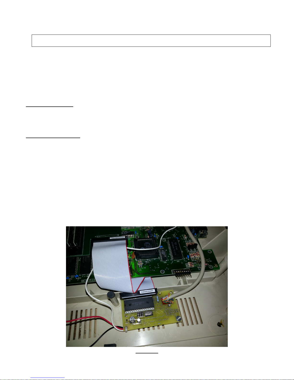
The interface will be mounted underneath the keyboard, refer to figure 1.. The case slots will
be used so no drilling is required. If a different method is used it will be the end user’s
responsibility to find an alternate method of securing the adapter to the CoCo’s case. The
ribbon cable will then connect the keyboard adapter to the motherboard via the CoCo's mylar
keyboard connector. If you would like to use both keyboards, then you must procure the ‘Pass
Through Connector’ adapter from Cloud-9.
Figure 1
6
Page 6
1. Make sure all power is removed and all cables unplugged from the Color Computer.
2. Remove all screws on the bottom of the computer. Note that the shorter screws are
removed from the front of the computer by the keyboard, longer screws will be placed in
the rear. Damage will occur to the case if you place the long screws in the front of the
case.
3. Remove the keyboard from it’s mounting position and motherboard connection.
4. Plug the PS/2 interface into the CoCo’s mylar keyboard connector. Inspect the pins to
ensure they are aligned with the contacts on the mylar connector.
5. Optional - Plug the CoCo keyboard into the pass-through connector on top of the
interface. Ensure that the conductive strips on the mylar film line up with the pins on the
connector. By using the pass through, both the PS/2 and CoCo keyboards can be used
at the same time.
6. Route the PS/2 keyboard cable to exit out the cartridge port or back by the RESET
switch. To get the case to close without binding. A small notch can be cut into the lower
half of the case. This is undetectable when the upper case is placed back on.
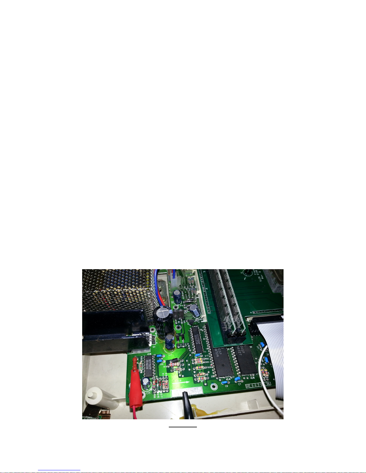
7. The red alligator clip goes to +5V. On a CoCo III this is most readily available on a large
resistor which stands away from the circuit board (R19, far left side of the circuit board;
connect to the pin nearest the front of the CoCo), refer to figure 2.
8. The black alligator goes to ground. Attatch to the metal grounding plate for the
keyboard located on the CoCo3’s circuit board. If you're not sure, ask someone who
knows as a mistake here could damage the interface and/or the CoCo, refer to figure 2.
Figure 2
7
Page 7
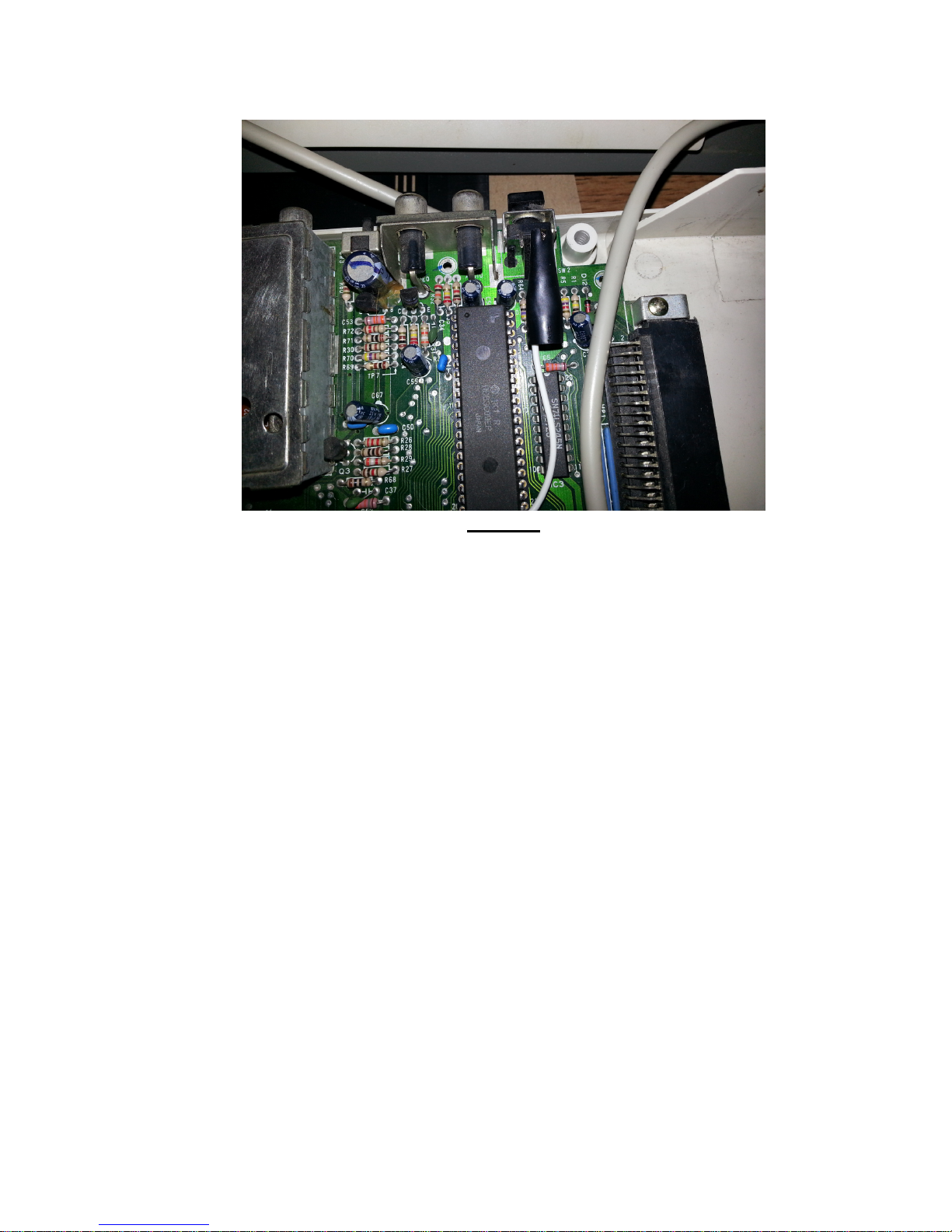
9. The white wire alligator clip connects to the CoCo's reset button. On the CoCo 3, the
rightmost pin on the top of the reset button is where the clip should go, refer to figure 3.
Figure 3
10. Close the cover and replace the screws that were removed in Step #2. Watch the
screw lengths.
11. Connect all cables , cords and apply power.
8
Page 8
Optional Pass Through Connector
The optional pass through connector assembly allows both keyboards to function. Performing
the installation above, the CoCo’s internal keyboard was not connected, thus it will be unable
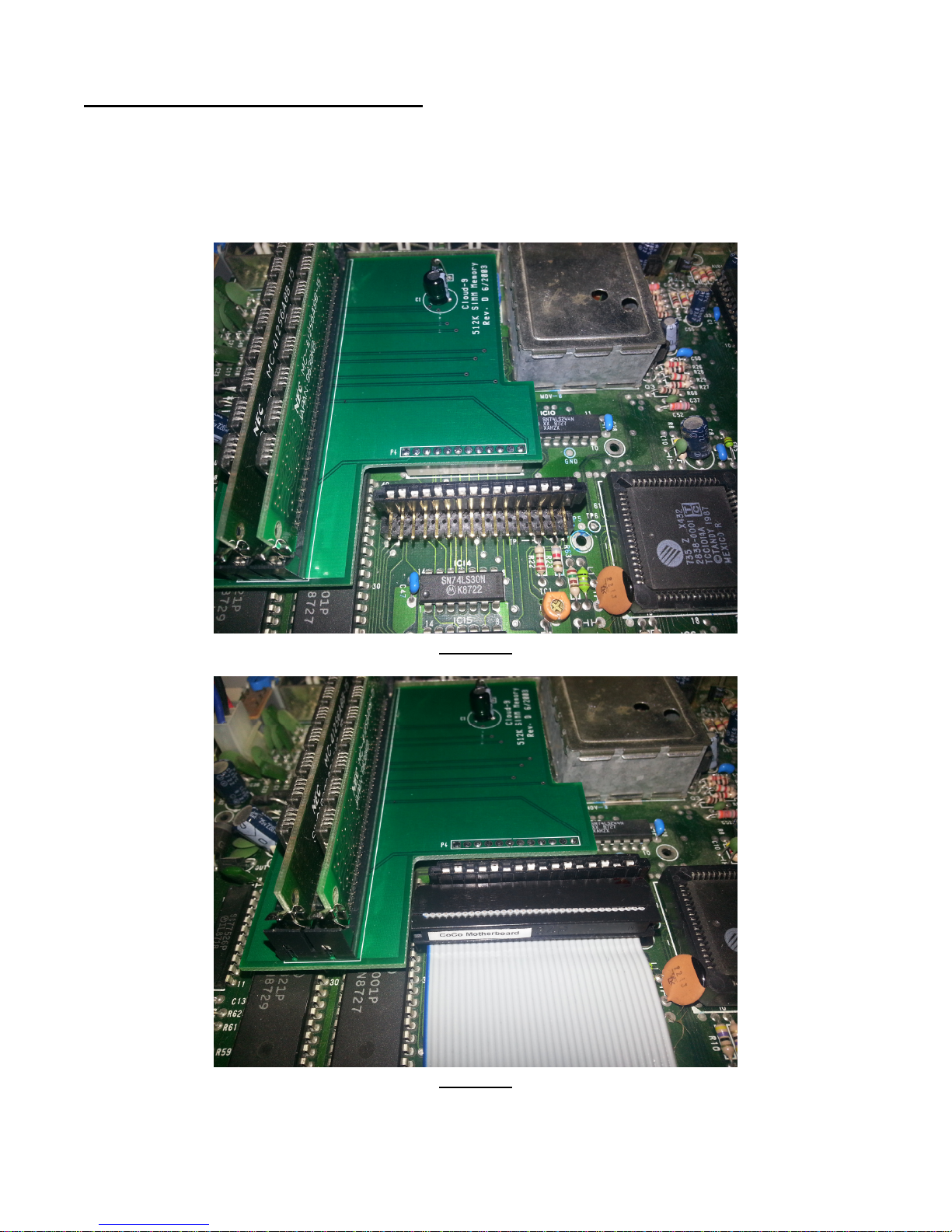
to be used. This connector assembly ties both the CoCo’s keyboard and the PS/2’s keyboard
matrix chip in parallel. See figures 4 & 5 for the connector installation.
Figure 4
Figure 5
9
Page 9

3. Operation
Key map
If you take a close look at both a CoCo and AT keyboard, you will soon realize that there is a
distinct difference in the layout of non-alphabetic keys. This interface supports the PS/2’s
keyboard map. Under NitrOS-9 almost all keys are produced with one exception, ` key . If
under RSDOS and a non displayable key is pressed, the interface adapter will output the
proper scan to produce the key, but Extended Color Basic will not interpret it for proper
display. To perform a listing scroll lock feature, press the
@ character.
NumLock
The
NUMLOCK
behavior of the keypad keys. When the
as the keys "0"-"9" and ".". When
arrow keys and macro keys to the keypad's immediate left. The power on state of this key is
programmable. To alter the state of this parameter, it is a toggle function. If the
is ON and you would like to have
sequence:
1. Press P
2. Press
3. Press P
key toggles the state of the corresponding keyboard LED, and changes the
AUSE/BREAK,
NUMLOCK,
AUSE/BREAK,
NUMLOCK
NUMLOCK
NUMLOCK
now entering programming mode.
to toggle function.
now exiting programming mode.
LED is on, the keypad keys behave the same
is off, the keypad keys behave the same as the
LED OFF at power up, perform the following key
SCROLL LOCK,
this will generate the
NUMLOCK
LED
CapsLock
Pressing the
lock is on, the interface will automatically press
typed. Note that this doesn't affect the computer's caps lock state. If the
and you would like to have
sequence:
1. Press P
2. Press
3. Press P
CAPSLOCK
AUSE/BREAK,
CAPSLOCK,
AUSE/BREAK,
key toggles the keyboard's caps lock state. While the keyboard's caps
CAPSLOCK
SHIFT W
LED ON at power up, perform the following key
henever an alphabetic character is
CAPSLOCK
LED is OFF
now entering programming mode.
to toggle function.
now exiting programming mode.
Macro Keys Overview
One of the best features of this interface is it's ability to use the extra keys on the PS/2
keyboard as macro keys. This interface has two different macro modes, pre-canned and
custom.
Macro Keys - Pre-Canned
In pre-canned macro mode, the function keys F3-F12 have predefined functions that can’t be
altered. Pressing the
WINDOWSKEY MACROKEY
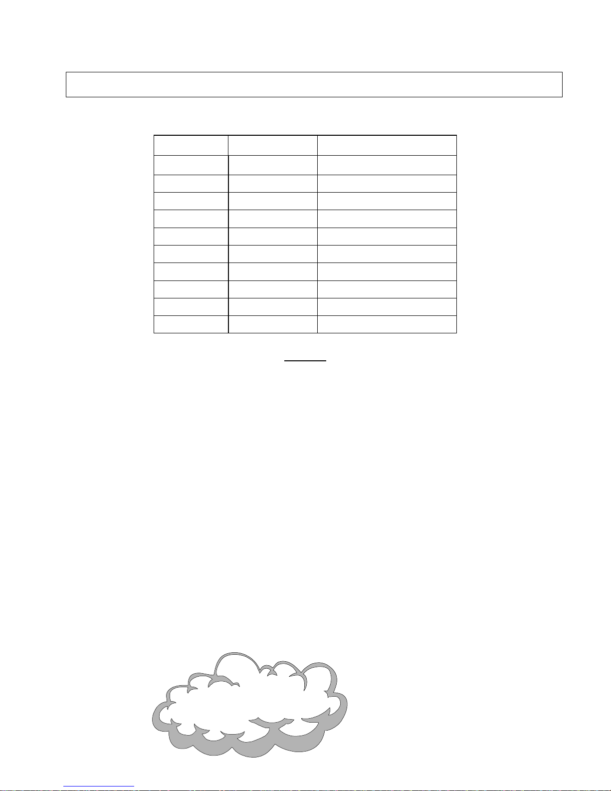
Table 1 for key command correlation for the different operating systems.
SHIFT MACROKEY
will perform a NitrOS-9 command lookup and the
will perform a Extended Color Basic command lookup. Please refer to
10
Page 10

Macro Keys - Custom
A custom sequence of keystrokes can be associated with each macro key, F3-F12. The
sequence is re-played whenever the key is hit. This is especially useful for commonly used
commands, and for defining application specific key combinations. The macro sequences are
re-definable at any time through the keyboard, and are saved indefinitely. Each of the ten
available macro keys can have up to 50 keystrokes stored. The sequence is stored exactly as
typed.
The timing of keystrokes is not stored, so the keys are replayed at a fixed rate regardless of
the delay between keystrokes when recorded. The macro keys are F3 through F12. The
following example is programming the F3 function key.
To define a macro key, perform the following steps:
1. Press P
2. Press F3.
3. Type the sequence of characters you want to record.
4. Press P
The P
AUSE/BREAK
Pressing ANY function key will automatically exit you from the recording function. This is
feature will not allow you to stack your macro sequences. So using a macro key in a macro
sequence is NOT allowed. If
session, this is also not allowed and the recording session will auto exit. The recording will also
stop if the sequence exceeds 50 bytes in length. To erase a macro, simply perform steps 1,2,4
in the above example. To play a macro, press the macrokey. The keys are played back at a
predetermined rate which cannot be adjusted. The playback is not affected by the state of the
keyboard caps lock when invoked; the state of the keyboard caps lock is significant only when
the macro is recorded. In contrast, the state of the CoCo caps lock does not affect the
recording, but it is significant when the macro is played back. Note that while recording a
macro, if an error is made and the
backspace event in it.
AUSE/BREAK,
AUSE/BREAK,
now entering programming mode.
now exiting programming mode.
key is not required to be pressed upon exiting the macro recording function.
CAPSLOCK
BACKSPACE KEY
or
NUMLOCK
are pressed during a macro recording
is used, the stored sequence will have the
Keyboard Reset
Another desirable feature of the interface is the ability to reset the CoCo via the
DELETE
CoCo's
key combination. Pressing
CTRL A
nd
ALT
keys while resetting. This is useful for forcing a cold restart on the CoCo
3.
Firmware Version
Another feature of the interface is the ability to display the firmware revision of the interface’s
uC. This function is performed by pressing the S
upgrade, the new version number will be updated on the web site. This product is not field
upgradeable, so the interface will have to be sent in to Cloud-9 to be re-flashed with the
current firmware.
SHIFT CTRL ALT DELETE CA
HIFT PAUSE/BREAK.
11
CTRL ALT
uses the interface to hold down the
In the event of a firmware
Page 11
4. Pre-Canned Macros
3749 County Road 30
SE
Delano,
MN 55328
www.cloud9tech.com
Key
F3 dir<cr> DOS<cr>
F4 dir –x<cr> DIR
F5 shell i=/ LOAD”
F6 mdir -e<cr> RUN<cr>
F7 mfree<cr> LIST<cr>
F8 procs -e<cr> LOADM”
F9 format EXEC<cr>
F10 date –t<cr> COPY”
F11 rename BACKUP
F12 copy RENAME”
Shift WindowsKey
Table 1
Manual Revision 1.2
July 16, 2013
Cloud-9
Cloud-9
12
 Loading...