

Page 1
RL-1, RSL-4, RSL-6 Installation Guide V1.0
1
RL-1, RL-1A, RSL-4, RSL-4A,
RSL-6, RSL-6A
Remote Control Plates
Installation Guide
Page 2

RL-1, RSL-4, RSL-6 Installation Guide V1.0
2
Page 3
RL-1, RSL-4, RSL-6 Installation Guide V1.0
3
Contents
Introduction ...................................................................4
Remote plate types ................................................................................. 5
Compatible Cloud products.................................................................. 6
Single and multi-channel operation ...................................................... 8
Device conguration ............................................................................... 9
Wiring details .........................................................................................11
CX163 stereo control options ........................................................... 13
Wiring diagrams ..................................................................................... 14
Page 4
RL-1, RSL-4, RSL-6 Installation Guide V1.0
4
Introduction
Cloud RL and RSL remote control plates are accessories for a wide range
of Cloud zoners, mixer-ampliers and power ampliers. They are compatible
with all current (relevant) products, and also with numerous discontinued
products.
RL plates adjust the signal level in an audio channel of a Cloud device, and
thus allow audio volume in an area to be controlled locally.
RSL plates provide the same volume control function as RL plates,
but additionally allow remote selection of music source, when used in
conjunction with Cloud devices that have multiple line inputs.
Page 5

RL-1, RSL-4, RSL-6 Installation Guide V1.0
5
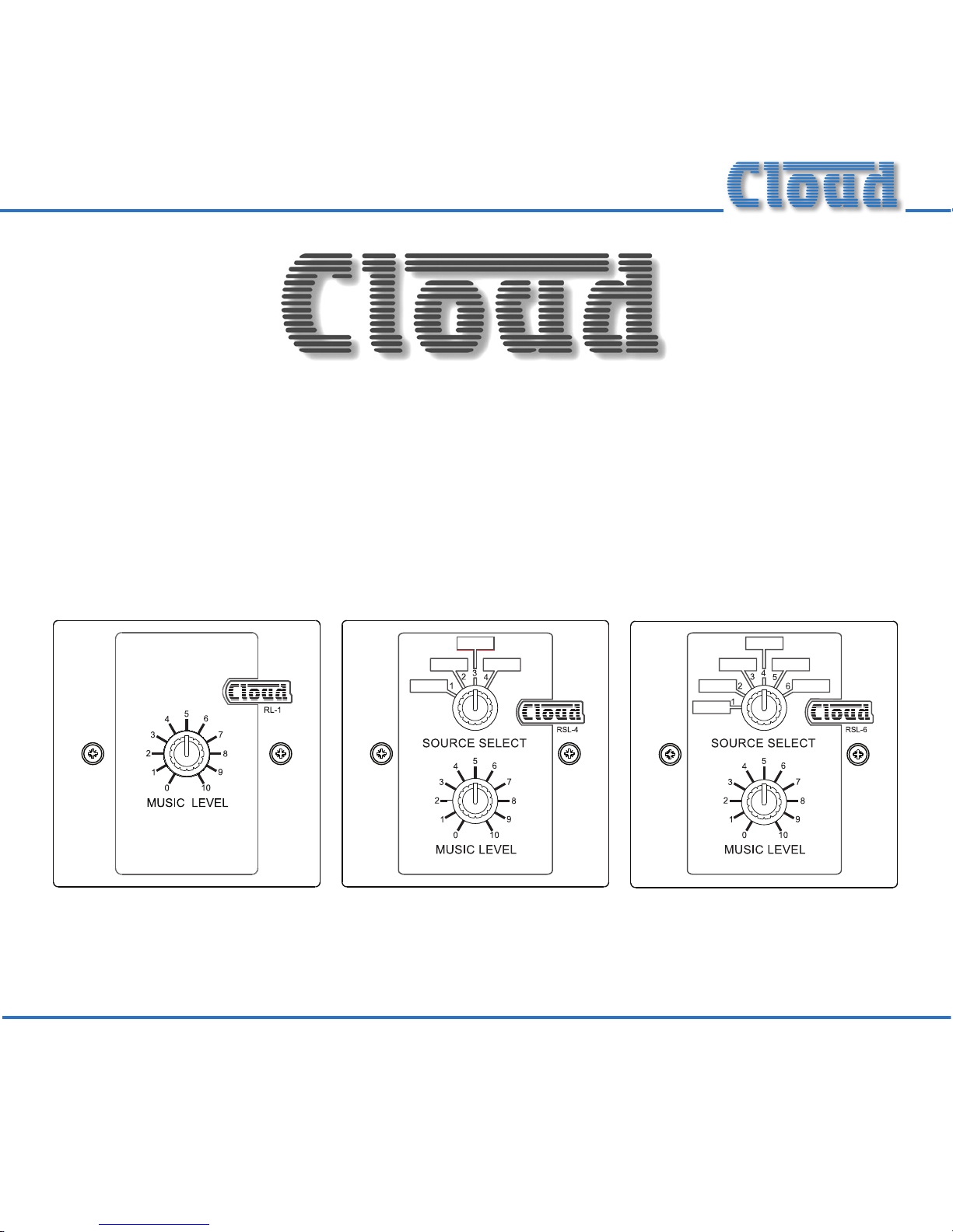
Remote plate types
Functionally, there are three models of remote plate:
• RL-1: provides remote volume control of an audio channel.
• RSL-4: provides remote volume control of an audio channel, and also
remote selection of the music source for that channel, when
used with devices having up to four line inputs.
• RSL-6: as RSL-4, but for use with devices having up to six line inputs.
All three plates t standard UK-style single-gang electrical back boxes, either
surface-mounting or ush-tting. Recommended back box depth is 25 mm.
Two M3.5 x 20 xing screws are supplied with each plate.
US Versions:
The RL-1A, RSL-4A and RSL-6A are electrically and functionally identical,
but the faceplates have different physical dimensions (4.51”x 2.76”)
which allow them to be mounted into a standard US-style back box (with
vertical orientation). All information in this manual applies equally to both
mechanical versions.
Page 6

RL-1, RSL-4, RSL-6 Installation Guide V1.0
6
Compatible Cloud products
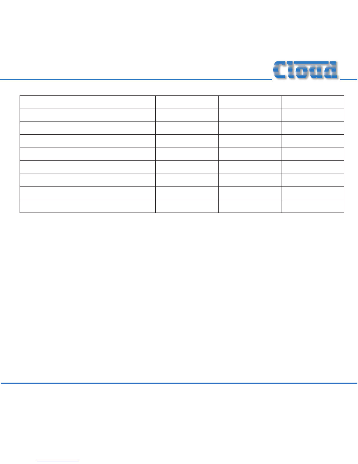
The table below summarises which current Cloud products are compatible
with each type of plate. For older products, please consult the product’s
Installation Guide, www.cloud.co.uk, or contact Cloud’s Technical Dept.
PRODUCT RL-1/1A RSL-4/4A RSL-6/6A
Venue Mixers
Z4II
✔ ✔
Z8II
✔ ✔
Zone Mixers
CX163
✔
CX263
✔ ✔
CX261
✔ ✔
CX462
✔ ✔
Integrated Mixer-ampliers
MA60
✔ ✔
MA60MEDIA
✔ ✔
36/50
✔ ✔
46/50
✔ ✔
Page 7

RL-1, RSL-4, RSL-6 Installation Guide V1.0
7
Power ampliers RL-1/1A RSL-4/4A RSL-6/6A
MPA60
✔ ✔
MPA120
✔ ✔
MPA240
✔ ✔
CXV225*
✔
CXV425*
✔
CXA450*
✔
CXA850*
✔
CXA6*
✔
VTX4120
✔
VTX4240
✔
VTX4400
✔
* These models require VCA cards to be installed before they can be used with remote control plates.
Full installation instructions are provided with the VCA card kit, and can also be found in the Installation Guide for
the model.
Page 8

RL-1, RSL-4, RSL-6 Installation Guide V1.0
8
Single and multi-channel operation
RL and RSL remote plates are primarily designed to provide remote control
of a single audio channel. A single channel will often correspond to a single
zone or area of a building, and the remote plate will therefore control the
audio in that zone, but see NOTE below. Many of the products listed above
have two or more audio channels; on all such Cloud devices, provision is
made for connecting separate remote control plates to as many channels as
required. (The CX163 stereo zone mixer has a slightly different arrangement;
see Wiring details on page 11 and Wiring diagrams on page 14 for further
information).
NOTE: It is possible to control two or more channels of a Cloud multichannel device “in parallel” from a single remote plate; this might be desirable
where, e.g., more than one channel of a mixer-amplier is powering speakers
in the same zone, due to room size.
An RL-1/1A may be wired in parallel to more than one channel of an
amplier or zoner, but note that the “law” of the control will differ from that
obeyed when it is used with a single channel. When wired to several channels
in parallel, this may produce an inconvenient “cramping” of the control’s
operation at one end of the range.
Page 9

RL-1, RSL-4, RSL-6 Installation Guide V1.0
9
The RSL-4/4A and RSL-6/6A remote control plates require modications
for multi-channel operation. This topic is NOT covered in this manual.
Installers requiring this option should download the appropriate Cloud
Technical Note from www.cloud.co.uk, and carry out the modications
described before installing the plates.
Device conguration
Most RL/RSL-compatible Cloud products will require minor conguration
changes when remote control plates are installed to ensure correct operation.
RL plates:
When adding RL-1/1A remote control plates, it will generally be necessary
to disable the front panel music level control, so that volume may be
adjusted only by the plate. On most units, this is done by operating a rear
panel push-button switch. However, on devices with multiple music sources,
doing this will also disable the front panel music source control. To maintain
control of music source from the front panel, internal jumpers must be set
to the appropriate position. The products to which this applies are those
which are also compatible with RSL plates (see Compatible Cloud products
table on page 6).
Page 10

RL-1, RSL-4, RSL-6 Installation Guide V1.0
10
RSL plates:
When adding RSL-4/4A or RSL-6/6A remote control plates, it will generally
be necessary to disable both the front panel music level and source selection
controls, so that full control is via the plate. On most units, this can be done
by operating a rear panel push-button switch.
IMPORTANT
With both types of plate, it is essential that installers check the Installation
Guide for the specic product to which they are connecting the plates. This
will give full details of the conguration procedure. If necessary, Installation
Guides for all products can be found at www.cloud.co.uk.
On multi-channel (or multi-zone) devices, the conguration changes
necessary for remote control are always per-channel or per-zone. Channels
(or zones) to which remote control plates are not tted will operate from
the unit’s local controls in the normal way.
Page 11

RL-1, RSL-4, RSL-6 Installation Guide V1.0
11
Wiring details
In most cases, remote control plates connect to their host devices via perchannel, 3-pin 5 mm-pitch screw terminal connectors on the device’s rear panel.
The only exception is the CX163, which has a 4-pin connector. The connector
will be labelled REMOTE LEVEL, REMOTE LEVEL/SOURCE, REMOTE MUSIC
CONTROL, or something similar, depending on the device.
On all types of remote control plate, connection at the plate is via a rear
3-pin screw-terminal connector.
RL plates: Connection may be via single- or twin-core screened cable. RL
plates can generally be connected to devices that support remote music
source selection using single-core cable, but two-core screened cable is
required when connecting to devices that do not support this.
RSL plates: These always require twin-core screened cable.
The use of crimp ferrule-type terminals is recommended for the
cable terminations as this will provide a much more reliable long-term
connection. Recommended maximum cable length is 100 m (328 ft.)
Page 12

RL-1, RSL-4, RSL-6 Installation Guide V1.0
12
The wiring scheme to be adopted varies between devices. See the table
below to check which of the wiring diagrams on pages 14 and 15 should be
followed to connect a particular type of plate to a specic device.
PRODUCT RL-1/1A RSL-4/4A RSL-6/6A
Venue Mixers
Z4II A E
Z8II A E
Zone Mixers
CX163 C or D*
CX263 A E
CX261 A E
CX462 A E
Integrated Mixer-ampliers
MA60 A E
MA60MEDIA A E
36/50 A E
46/50 A E
Power ampliers
MPA60 A E
MPA120 A E
Page 13
RL-1, RSL-4, RSL-6 Installation Guide V1.0
13
MPA240 A E
CXV225* B
CXV425* B
CXA450* B
CXA850* B
CXA6* B
VTX4120 B
VTX4240 B
VTX4400 B
*See note below
CX163 stereo control options
The CX163 is a two-zone stereo mixer and has a different remote control
connector to other Cloud units. When using RL remote level control
plates with a CX163, the installer has the option of using a single RL plate
to control both left and right channels together (i.e., stereo operation),
or of using two separate RL plates to control the left and right channels
independently. For stereo operation, use wiring diagram C. For separate L/R
control, use wiring diagram D.
Page 14

RL-1, RSL-4, RSL-6 Installation Guide V1.0
14
Wiring diagrams
123
REMOTE MUSIC
CONTROL
CONNECTOR
123
REMOTE LEVEL CONTROL WIRING
RL-1/1A
SINGLE-CORE SCREENED CABLE MAY BE USED
WIRING DIAGRAM A
RL-1/1A
123
REMOTE MUSIC
CONTROL
CONNECTOR
123
REMOTE LEVEL CONTROL WIRING
RL-1/1A
WIRING DIAGRAM B
USE TWO-CORE SCREENED CABLE
123
REMOTE MUSIC
CONTROL
CONNECTOR
123
REMOTE LEVEL CONTROL WIRING
RL-1/1A
WIRING DIAGRAM C
USE TWO-CORE SCREENED CABLE
4
Page 15

RL-1, RSL-4, RSL-6 Installation Guide V1.0
15
123
REMOTE MUSIC
CONTROL
CONNECTOR
123
REMOTE SOURCE & LEVEL CONTROL WIRING
RSL-4/4A
or
RSL-6/6A
USE TWO-CORE SCREENED CABLE
WIRING DIAGRAM E
RSL-4/4A or RSL-6/6A
123
123
REMOTE LEVEL CONTROL WIRING
RL-1/1A
WIRING DIAGRAM D
USE TWO-CORE SCREENED CABLE
4
123
RL-1/1A
LEFT CHANNEL
RIGHT CHANNEL
(CX163 ONLY)
REMOTE MUSIC
CONTROL
CONNECTOR
RL-1/1A
Page 16

Cloud Electronics Limited
140 Staniforth Road
Shefeld S9 3HF
England
Tel: +44 (0)114 244 7051
Fax: +44 (0)114 242 5462
email: info@cloud.co.uk
web: www.cloud.co.uk
 Loading...