

Page 1

[
-iji
'ii
_________________ I
~~!!!E= __
MA40F
&
MA40T
Mini Amplifiers
rl.......
.IC LINE' LJNEZ LF HF
.....v........
:J;i;k. ,"",
:"'<
:J;i;k. :J;i;k.
@
1l!ilIMl@!?0 0 0 ~~
.::'@.~~l@l;.:~. :~~.
@
~~~~~~~~~~~~~~~~~~~~~
~~~~~~~~~~~~~~~~~~~~~
".1.......
.c
LJlIE' •••• Z LF HF
.....v........
-i;i;!r ,'" '"
,""-i;i;!r
@
[lIjJ1!.\~'jj'
0 0 0
,;l""'~~:
.::'®;~ ~. :~.
@
Installation and User Guide
MA40F/MA40T Installation and User Guide vl.O
Page 2
WARNING:
To reduce the risk of fire or electric shock, do not expose this appliance to rain or
moisture.
A
WARNING: SHOCK HAZARD - DO NOT OPEN
AVIS:RISQUE DE CHOC ELECTRIQUE - NE PAS
OUVRIR
The lightning flash with the arrowhead symbol
within an equilateral triangle, is intended
to alert you to the presence of uninsulated
dangerous voltages within the product's
enelosure that may be of sufficient magnitude
to constitute a risk of electric shock.
The exclamation point within an equilateral
triangle is intended to alert the user to
the presence of important operating and
maintenance (servicing) instructions in the
literature accompanying the appliance.
2 MA40F/MA40T Installation and User Guide vl.O
Page 3
[
-i
-ili::
_ __'5_
IMPORTANT SAFETY INSTRUCTIONS
I. Read these Instructions.
2. Keep these Instructions.
3. Heed allWarnings.
4. Follow all Instructions.
s.
Do not use this apparatus near water.
6. Clean only with a dry cloth.
7. Do not bleek any ventilation openings. Install in accordance with the
manufacturer's instructions.
8. Do not install near any heat
sourees
such as radiators, heat registers, stoves or
other apparatus (including amplifiers) that produce heat.
9. Do not defeat the safety purpose of the polarized or grounding - type plug.A
polarized plug has two blades with one wider than the other.A grounding type
plug has two blades and a third grounding prong. The wide blade or the third
prong are provided for your safety.When the provided plug does not fit into
your outlet, consult an electrician for replacement of the obsolete outlet.
10.
Protect the power cord from being walked on or pinched particularly at plugs,
convenience receptacles, and the point where they exit from the apparatus.
I I. Only use attachments/accessories specified by the manufacturer.
12.
®
-
Use only with the cart, stand, tripod, bracket or table specified by
the manufacturer or sold with the apparatus, when a cart is used,
use caution when moving the cartlapparatus combination to avoid
injury from tip-over.
13.
Unplug this apparatus during lightning storms or when unused for long periods
of time.
14.
Refer all servicing to qualified service personnel. Servicing is required when the
apparatus has been damaged in any way, such as power-supply cord or plug is
damaged, liquid has been spilied or objects have fallen into the apparatus, the
apparatus has been exposed to rain or moisture, does not operate normally, or
has been dropped.
MA40F/MA40TInstallation and User Guide vl.O 3
Page 4
A
Do not expose the apparatus to dripping or splashing, and ensure that
.a
no objects filled with water, such as vases, are placed on the apparatus.
L'appareil ne doit pas être exposé aux écoulements ou aux éclaboussures et aucun
objet ne contenant de liquide, tel qu'un vase, ne doit être placé sur I'objet.
The mains plug is used as the disconnect device and it should remain
readily accessible during intended use.ln order to isolate the apparatus
from the mains, the mains plug should be completely removed from the
mains outlet socket.
La prise du secteur ne doit pas être obstruée ou doit être facilement accessible
pendant son utilisation. Pour être complètement déconnecté de I'alimentation
d'entrée, la prise doit être débranchée du secteur.
Terminals marked with the ~ symbol may use Class 2 Wiring, but
voltages at these terminals may be of sufficient magnitude to
constitute a risk of electric shock. The external wiring connected to
these terminals requires installation byan instructed person or the use
of pre-made leads or cords.
4 MA40F/MA40T Installation and User Guide vl.O
Page 5
[
-i
-ili::
_ __'5_
Contents
IMPORTANT SAFETY INSTRUCTIONS
3
SAFETY INFORMATION
7
SafetyNotes regarding Installation 7
Conformities 7
RoSHandWEEE declaration 8
SafetyConsiderations and Information 9
Mains Fuse 9
Servicing 9
OVERVIEW 10
Introduction 10
Applicable Models 10
MA40F/MA40T mainfeatures I I
What's in the Box 12
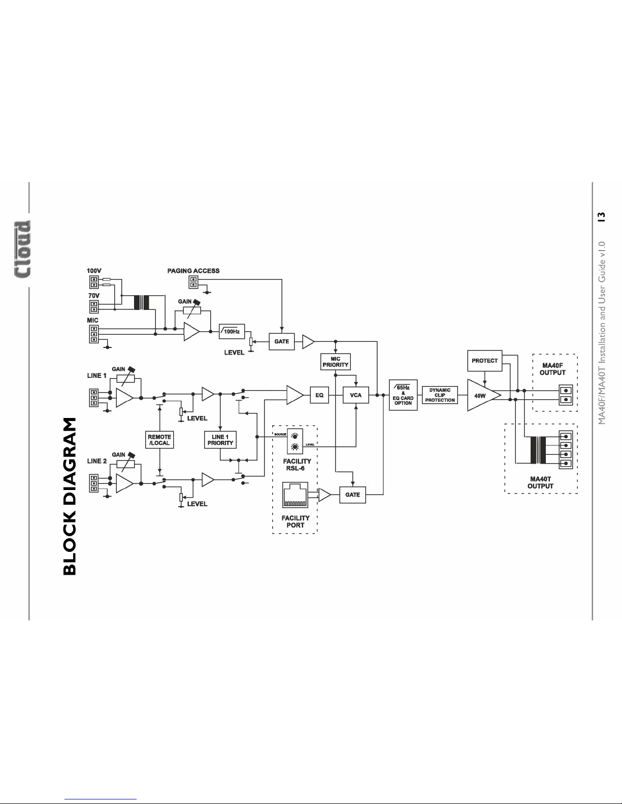
BLOCK DIAGRAM
13
FRONT PANEL DESCRIPTION
14
REAR PANEL DESCRIPTION 15
INSTALLATION 17
Mechanical 17
Ventilation 18
Connections and adjustments 19
Line inputs 19
Sensitivity&Gain Control 20
Music Leveland EQ control 20
Line I Priority 20
Mic inputs 21
Balancedinput 21
701
IOOVline input 22
Mic gainadjustment 23
Microphone levelcontrol 23
Pagingcontrol and mic priority 23
Output 25
Lo-Z output (MA40F only) 25
Connecting to
100170/25
V line systems(MA40T only) 25
Facility Port 26
MA40F/MA40TInstallation and User Guide vl.O 5
Page 6
Connecting an LM-2 or BT-I 28
Connecting an RL or RSL Series remote control plate 30
Using the Facility Port as an auxiliary input 31
Control of music souree and level via external DC 31
Music Mute Input 33
Auto Power Down 34
Loudspeaker EQ cards 34
Installation Instructions 35
APPENDIX
36
PCB layout diagram 36
Table of internal jumpers and default settings 37
Summary of rear panel DIP switch functions 38
EMC considerations 40
Earthing 40
Technical specifications 41
6 MA40F/MA40T Installation and User Guide vl.O
Page 7

[
-i
-ili::
_ __'5_
SAFETY INFORMATION
Safety Notes regarding Installation
Do not expose the unit to water or moisture.
Do not expose the unit to naked flames.
Do not block or restriet any air vent.
Do not operate the unit in ambient temperatures above 35°C.
Do not touch any part or terminal carrying the hazardous live symboltwhile
power is supplied to the unit.
Do not perform any internal adjustments unless you are qualified to do so and
fully understand the hazards associated with mains-operated equipment.
The unit has no user-serviceable parts. Refer servicing to qualified service
personnel.
Ifthe moulded plug is cut off the AC power lead for any reason, the discarded
plug is a potential hazard and should be disposed of in aresponsibie manner.
Conformities
This product conforms to the following European EMC Standards:
BS EN 55103-1:2009
BS EN 55103-2:2009
CE
This product has been tested for use in commercial and light industrial environments.
If the unit is used in controlled EMC environments, the urban outdoors, heavy
industrial environments or close to railways, transmitters, overhead power lines,
etc., the performance of the unit may be degraded.
The product conforms to the following European electrical safety standards:
BS EN 60065:2002 (+A2:2010)
UL60065
This product is compliant with the relevant provisions of:
Energy Star® EligibilityCriteria Ver 3.0 for Audio-Video products.
MA40F/MA40TInstallation and User Guide vl.O 7
Page 8

RoSH and WEEE declaration
Cloud Electronics Limited manages its business and collaborates with its suppliers
to comply with the European Union restriction of the use of certain hazardous
substances in electrical and electronic equipment, RoSH Directive (2002/95/EC),
that came into force onIst July 2006, and similar restrictions in other jurisdictions.
The "crossed out wheelie bin" symbol on the product and represented
above is there to remind users of the obligation of selective collection
of waste. This label is applied to various products to indicate that the
product is not to be thrown away as unsorted municipal waste. At the
end of life,dispose of this product by returning it to the point of sale or
to your local municipal collection point for recycling of electric and electron ic
devices.
Customer partlcipation IS Important to rrururruze the potential effects on the
environment and human health that can result from hazardous substances that may
be contained in this product.
Please dispose of this product and its packaging in accordance with local and national
disposal regulations, including those governing the recovery and recycling of waste
electrical and electron ic equipment. Contact your local waste administration, waste
collection company or dealer.
8 MA40F/MA40T Installation and User Guide vl.O
Page 9
[
-i
-ili::
_ __'5_
Safety Considerations and Information
The MA40F and MA40T are powered byan external DC supply.A separate Power
Supply Unit (PSU) is supplied with the amplifier. The PSU must be earthed. Ensure
that the mains power supply provides an effective earth conneetion using a three-
wire termination.
Mains Fuse
The PSU is a sealed unit and contains no user-replaceable fuses. Mains over-current
proteetion
is provided by the fuse in the AC mains plug, which should be rated at
SA.
Servicing
The unit contains no user serviceable parts. Refer servicing to qualified service
personnel. Do not perform servicing unless you are qualified to do so. Disconnect
the power cable from the unit before removing the top panel and do not make
any internal adjustments with the unit switched on. Only reassemble the unit using
either the original bolts/screws, or ones identical to the original parts
MA40F/MA40T Installation and User Guide vl.O 9
Page 10
OVERVIEW
Introduction
The MA40F and MA40T are very compact mono amplifiers designed for integration
into audio and AV systems where de-centralised installation is advantageous. They
are intended as "install-and-forget" components, and are small enough to be fitted
into wall or ceiling voids or in any convenient location adjacent to projectors, flat
screen displays or loudspeakers. A simple set of controls and configuration options
makes them easy to integrate into any audio system.They are highly suitable for use
with in-store digital signage, gallery and museum exhibits and fixed or mobile tour
guide systems.
The MA40F can deliver 40W (mono) into a 4 ohm load, while the physically larger
MA40T includes an output transformer, enabling it to drive 100 V,70 V or 25 V
line loudspeaker systems. In all other respects, the two models are identical. There
are two unbalanced inputs for line level signals (typically music sources) and a
balanced mic input for paging/announcement use. An alternative mic input allows
the amplifier to be fed with paging/announcements from a 70/ IOOVline loudspeaker
system. Front panel preset-type controls are provided for music level, microphone
levels and music EQ. There are also various preset adjustments and configuration
DIP switches on the rear panel, and jumpers mounted internally on the main PCB.
A remote input module or remote level control can be wired to the amplifier's
Facility Port, which can also be used as an additional line input.
Applicable Models
This Installation Guide describes the installation and operation of the following
modeis:
• Cloud MA40F
• Cloud MA40T
40W mono amplifier for 4 ohm loudspeakers
40 W mono amplifier for 100/70125V line loudspeaker
systems
The two models differ in physical size, the MA40T being larger in order to
accommodate the internal line output transformer.Apart from the inclusion of this
transformer, the two models are essentially identical for the practical purposes of
installation and operation. Unless specifically stated otherwise, the information in
this Guide may be taken to apply to either model.
10 MA40F/MA40T Installation and User Guide vl.O
Page 11
[
-i
-ili::
_ __'5_
NOTE:
Amplifier models MA40 and MA40E are NOT covered by this Guide, and
when installing either of these modeis, reference should only be made to the Guides
specific to them.
MA40F/MA40T main features
• Two unbalanced stereo line inputs with individual sensitivity trims
• Electronically-balanced mic input with separate gain control
• 12V phantom power selectable by internal jumper
• Front panel control of music level and mic levels
• HF&LF EQ adjustments for music sourees
• MIC input configurable for direct connection to I00/70 V line system: allows
MA40F/T to receive announcements from main building PAiVAsystem
• MIC input can be used with paging mics
• Paging configurable as automatic voice-over-music (VOX mode) or contact
closure via access port
• Selectable LlNE l-over-LiNE 2 priority
• Facility port for conneetion of LM-2 remote mic/line input module via
screened Cat 5 cable; also allows remote control of music level
• 40 W power amplifier
• Two versions available: MA40F with low-impedance output, MA40T with
internal transformer for driving 100/70/25 V line systems
• Music Mute control input (N/O or N/C) for interfacing to an emergency
system
• Selectable 65 Hz high-pass filter for use with 100/70125V line systems
• Optional EQ cards available to suit various popular installation loudspeakers
• Automatic power-down function (user-selectable)
• Less than IW power consumption in sleep mode
• Convection cooled - silent in operation.
• PSU meets US DoE LevelVI energy requirements
• Power requirements:
• MA40F: 12 to 24V DC, 60W
• MA40T: 24 V DC, 60 W
• Universal AC adaptor included (both modeis), operates from 100 to 240 VAC
MA40F/MA40TInstallation and User Guide vl.O I I
Page 12
Available Options:
• RL Series remote control plates for music volume
• RSL Series remote control plates for Line I/Line 2 selection and music volume
• LM-2 remote mic/line input module with music volume control
• BT-I Bluetooth wireless audio input module
• EQ cards to match various popular installed-sound loudspeakers
What's in the Box
Please check the shipping carton for damage before opening. If there is damage,
please contact your Cloud agent and the shippers.
The packing carton should contain the following items:
• MA40F or MA40T amplifier
• External PSU (AC mains adaptor)
• IEC mains lead (AC cord) with moulded plug appropriate to the territory
• Set of mating plug-in screw-terminal connectors
• Set of four self-adhesive polyurethane feet
• This manual
12
MA40F/MA40T Installation and User Guide vl.O
Page 13
I~I
111
I~
1~lIllllItlll
I ~
100V
MA40T
OUTPUT
FACILITY '
PORT
Page 14
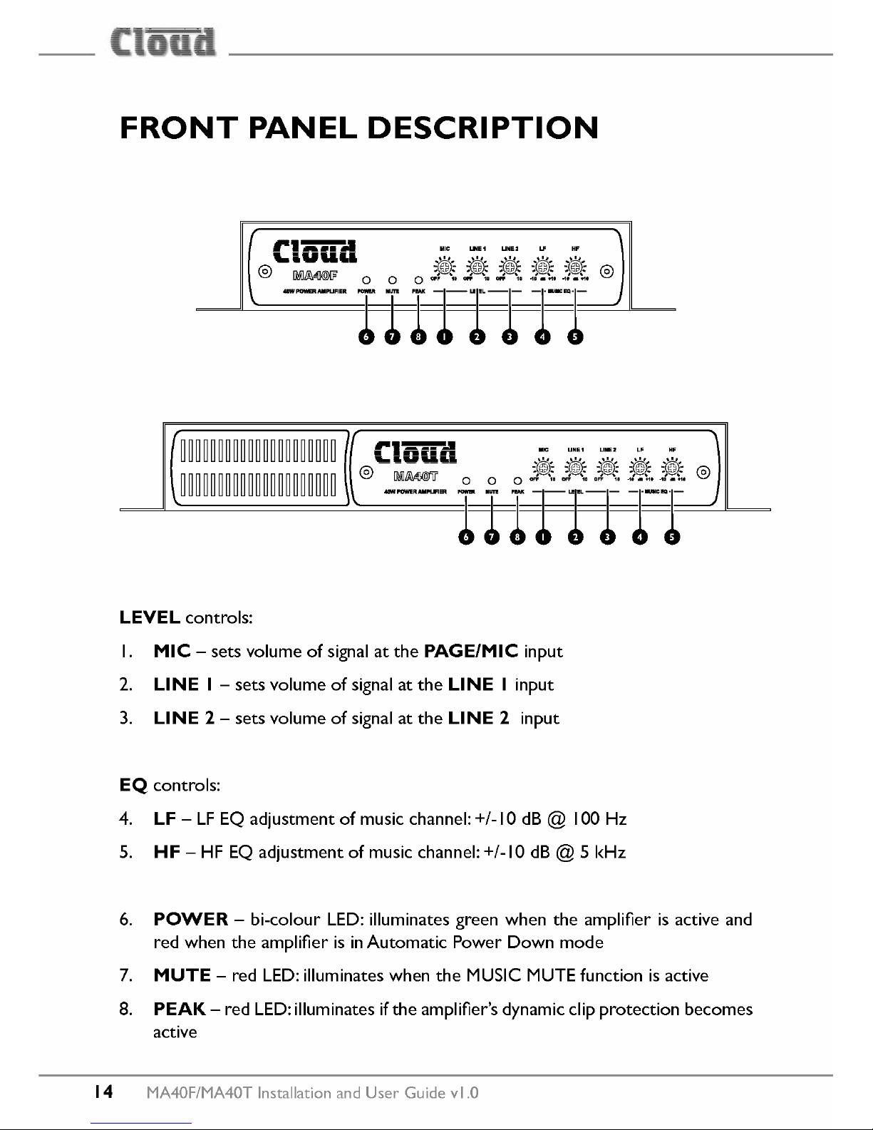
FRONT PANEL DESCRIPTION
~~~~~~~~~~~~~~~~~~~~~
~~~~~~~~~~~~~~~~~~~~~
LEVEL
controls:
I.
MIC -
sets volume of signal at the
PAGE/MIC
input
2.
LlNE I -
sets volume of signal at the
LlNE I
input
3.
LlNE 2 -
sets volume of signal at the
LlNE 2
input
EQ controls:
4.
LF -
LF
EQ adjustment of music channel: +/-10 dB @ 100 Hz
S.
HF -
HF
EQ adjustment of music channel: +/-10 dB @ 5 kHz
6.
POWER -
bi-colour LED: illuminates green when the amplifier is active and
red when the amplifier is inAutomatic Power Down mode
7.
MUTE -
red LED:illuminates when the MUSle MUTE function is active
8.
PEAK -
red LED:illuminates ifthe amplifier's dynamic clip proteetion becomes
active
14
MA40F/MA40T Installation and User Guide vl.O
Page 15

[
-i
-ili::
_ __'5_
REAR PANEL DESCRIPTION
I~I~~II~=II~~I~~II ~~~~~~~~~~~~~~~~~~~~~
~~~~~~~~~~~~~~~~~~~~~
I.
LlNE
land
LlNE 2 -
stereo line inputs for music sourees (unbalanced)
2.
GAIN -
two preset level trim controls (+/-10 dB) for each line input
3.
MIC -
balanced mic input
4.
70/1
OOVLlNE -
alternative high-voltage input, for conneetion to 70/ IOOVline
speaker systems
5.
PAIOV-
external paging access contacts input for Mic input
6.
GAIN -
preset gain control for mic input; range + I0 to +50 dB
7.
FACILITY PORT -
RJ45 socket for conneetion of remote input/control
modules such as the LM-2 and BT-I; it is also possible to connect an RL-lor
RSL-6 remote control plate to this port
8.
SPEAKER OUTPUT
(MA40F only) - speaker output for low-impedance
circuits
9.
SPEAKER OUTPUT
(MA40T only) - for connection to 100/70125 V line
loudspeaker system
MA40F/MA40T Installation and User Guide vl.O
15
Page 16
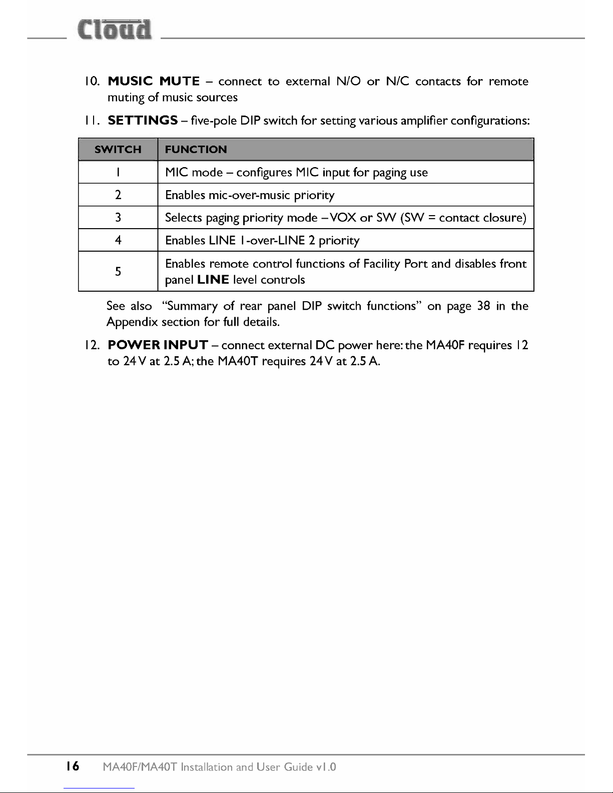
10.
MUSle MUTE -
conneet to external NfO or NfC contacts for remote
muting of music sourees
I I.
SETTINGS -
five-pole DIP switch for setting various amplifier configurations:
SWITCH FUNCTION
I MIC mode - configures MIC input for paging use
2 Enables mic-over-music priority
3 Selects paging priority mode - VOX or SW (SW=contact closure)
4 Enables LlNE l-over-LiNE 2 priority
5
Enables remote control functions of Facility Port and disables front
panel
LlNE
level controls
See also "Summary of rear panel DIP switch functions" on page 38 in the
Appendix section for full details.
12.
POWER INPUT -
conneet external DC power here:the MA40F requires 12
to 24 Vat 2.5 A; the MA40T requires 24 Vat 2.5 A.
16
MA40F/MA40T Installation and User Guide vl.O
Page 17
[
-i
-ili::
_ __'5_
INSTALLATION
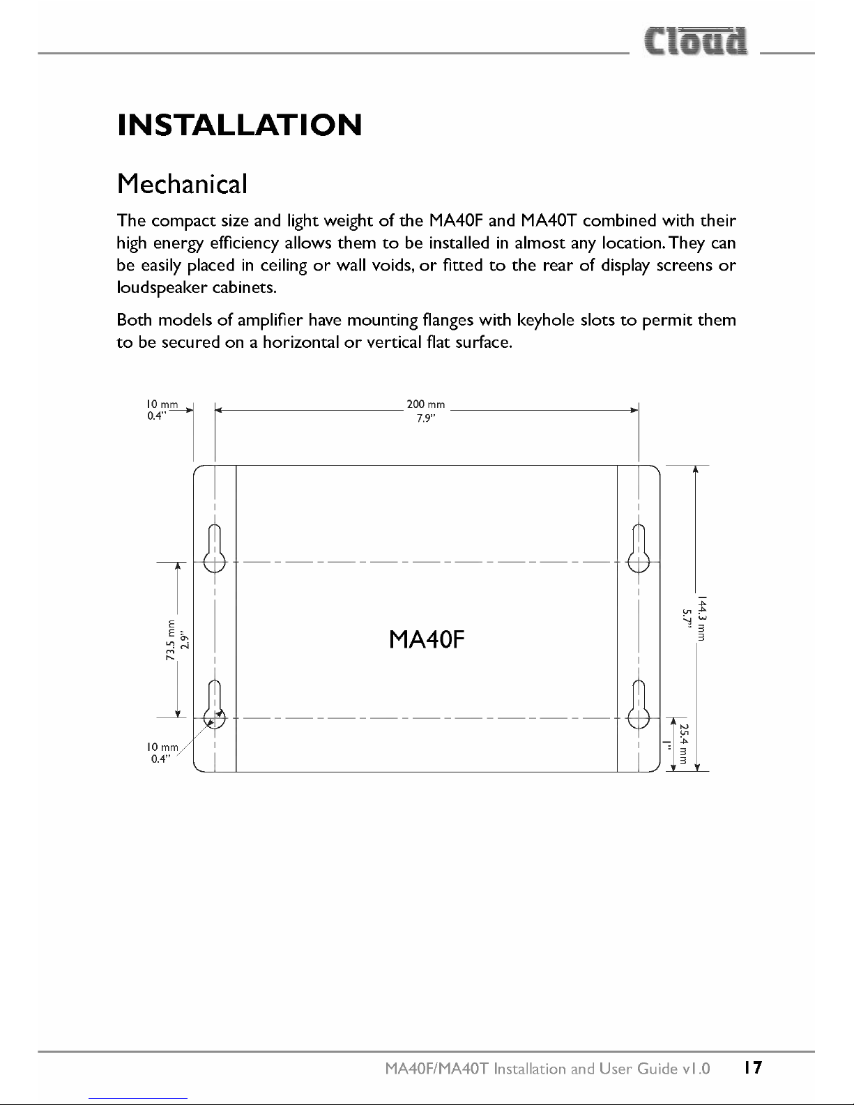
Mechanical
The compact size and light weight of the MA40F and MA40T combined with their
high energy efficiency allows them to be installed in almost any location. They can
be easily placed in ceiling or wall voids, or fitted to the rear of display screens or
loudspeaker cab inets.
Both models of amplifier have mounting flanges with keyhole slots to permit them
to be secured on a horizontal or vertical flat surface.
~.'~
.
~r-'--------------------------------------'-r~
~ 200mm------------------_.I
7.9"
MA40F
10
mm
0.4"
MA40F/MA40TInstallation and User Guide vl.O
17
Page 18

10
mm
l
~r-r--------------------------------------------------------r-.~
~ 28Jmm ~
11.14"
10
mm
0.4··
MA40T
1
I
I
.,
If using the MA40F/MA40T in a free-standing situation, the self-adhesive feet
(supplied with each amplifier) should be fitted.The amplifier should always be stood
on a flat surface. Care should be exercised in selecting alocation for a free-standing
unit, which should allow ventilation but be clear of any liquid or similar hazard.
Ventilation
The amplifiers use natural convection cooling, and care should be taken to locate
them where airflow is unrestricted (e.g., not under ceiling insulation material).
Consideration should also be given to ease of access, should the operational
configuration or audio levels need adjustment after installation.
In free-standing installations, always fit the polyurethane feet supplied, and do not
stand any other items on top of the unit.
18
MA40F/MA40TInstallationand User Guide vl.O
Page 19
[
-i
-ili::
_ __'5_
Connections and adjustments
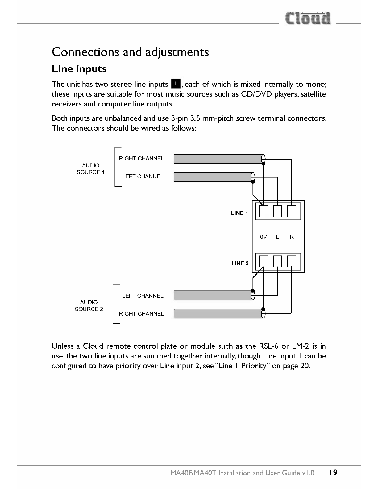
Line inputs
The unit has two stereo line inputs
a,
each of which is mixed internally to mono;
these inputs are suitable for most music sources such as CD/DVD players, satellite
receivers and computer line outputs.
Both inputs are unbalanced and use 3-pin 3.5 mm-pitch screw terminal connectors.
The connectors should be wired as follows:
L
IGHTCHANNEL
AUDIO
SOURCE1
LEFTCHANNEL
LlNE2
LlNE 1
[
LEFTCHANNEL
AUDIO
SOURCE2
RIGHTCHANNEL
Unless a Cloud remote control plate or module such as the RSL-6 or LM-2 is in
use, the two line inputs are summed together internally, though Line input I can be
configured to have priority over Line input 2, see "Line I Priority" on page 20.
MA40F/MA40T Installation and User Guide vl.O
19
Page 20
Sensitivity
&
Gain Control
Each of the stereo line inputs has an input impedance of 10kohms and a preset type
gain control on the rear panel adjacent to the input soekets
11.
The gain contrals
have a range of 20 dB allowing the input sensitivity to be varied from -12 dBu to
+8 dBu (0 dBu=0.775 Vrms). The gain contrals should be set so that the input
sou rees in use do not distort, and the front panel level contrals
0
and
0
have a
useful range.
Musie level and EQ eontrol
The front panel
LlNE land LlNE 2
contrals
0
and
0
should be adjusted during
installation to set the volume of the audio sou rees. The line inputs are summed
post the level controls; equalisation can be applied using the front panel
LF
and
HF
contrals • and
0,
which can apply a cut or boost of up to 10 dB at 50 Hz and
10kHz respectively.Adjust the EQ contrals to suit the audio programme material
being used, the speaker characteristics and the room acoustics. If the programme
material includes speech, the EQ should be adjusted for best intelligibility.
Ifthe line input levels are set too high,the amplifier's dynamic proteetion will activate
to prevent clipping and the front panel
PEAK
LED
0
will illuminate to indicate this.
Note that this LED also indicates an excessive mie signal level.
Line I Priority
Wh en both line inputs are in use, one audio souree can be given automatic priority
over the other by connecting it to Line I input and setting rear panel
SETTINGS
DIP switch 4
(LiNE I PRI)
to ON. This is a useful facility when a Digital Sound
Store, emergency announcement system or similar sou ree forms part of the audio
system.
Wh en Line I Priority is enabled, the amplifier will route the input signal at Line 2
normally until a signal is detected at Line I's input. When this happens, it switches
its music souree automatically to Line I. Once the signal at Line I stops (e.g., when
an announcement finishes), Line 2's souree will smoothly restore to its former level
over approx. 3 seconds.
20 MA40F/MA40T Installation and User Guide vl.O
Page 21
[
-i
-ili::
_ __'5_
Mie inputs
The MA40F and MA40T have a single microphone channel, enabling them to be
used for paging or announcements. By default, the mic channel is independent and
is simply mixed with the summed line inputs. The mic channel can be reconfigured
so that it operates as a standard Cloud-type paging input, with selectable mic-over-
line priority and triggering by either contact closure or automatic signal detection.
It is then compatible with paging microphones using zone selection by contact-
closure such as the Cloud PM range, including the PMI single-zone microphone. See
page 23 for more details.
The mic channel has two separate physical inputs: a standard balanced input and a
high-level transformer-isolated input for connection to
701
100V line systems. Both
inputs, and the connections for paging access, are on the 2 x 5-pin 3.5 mm-pitch
screw terminal connector
PAGE/Mie INPUT.
The microphone signal path includes a fixed high-pass filter. This attenuates the
response below 120 Hz, which helps to reduce the effects of microphone handling
noise.
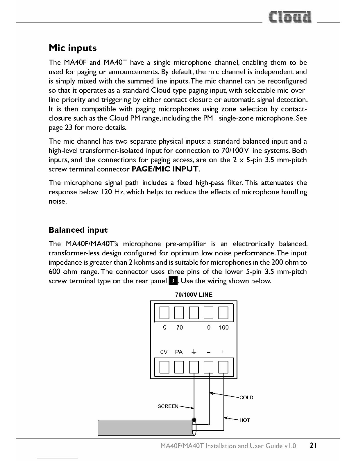
Balanced input
The MA40F/MA40T's microphone pre-amplifier is an electronically balanced,
transformer-Iess design configured for optimum low noise performance. The input
impedance isgreater than 2 kohms and is suitable for microphones inthe 200 ohm to
600 ohm range. The connector uses three pins of the lower 5-pin 3.5 mm-pitch
screw terminal type on the rear panel
11.
Use the wiring shown below.
70/100V LlNE
o
70
o
100
IDDDDDI
OV PA.,!,.
+
COLD
HOT
MA40F/MA40T Installation and User Guide vl.O
21
Page 22
12V phantom power is available at the mic input, and is activated by setting internal
jumper J6 to the ON position. See page 36 and page 37 for further information
regarding the internal jumpers. Care should be taken to ensure that phantom power
is activated only when the microphone connected to the input requires it - i.e., a
capacitor or electret type; other types of microphones (such as dynamic) may be
damaged ifa DC voltage is applied to them.
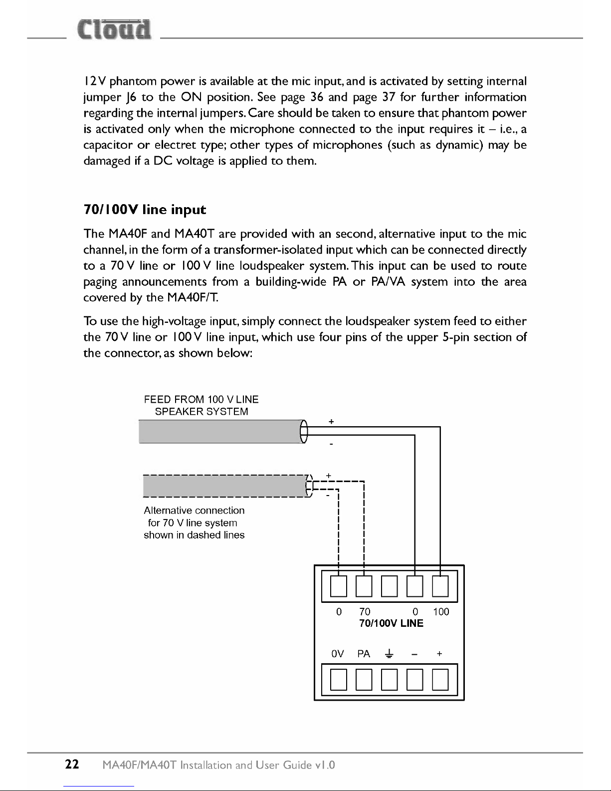
70/1
OOVline input
The MA40F and MA40T are provided with an second, alternative input to the mic
channel, in the form of a transformer-isolated input which can be connected directly
to a 70 V line or 100 V line loudspeaker system. This input can be used to route
paging announcements from a building-wide PA or PAiVA system into the area
covered by the MA40F/T.
To use the high-voltage input, simply connect the loudspeaker system feed to either
the 70 V line or 100V line input, which use four pins of the upper S-pin section of
the connector, as shown below:
FEED FROM 100 V LlNE
SPEAKER SYSTEM
+
---------------------7\
+
P:::;--l
---------------------~ - I I
I I
I I
I I
I I
I I
I I
I I
I I
Alternative connection
for 70 V line system
shown in dashed lines
o
70 0 100
70/100V LlNE
OV
PA.,!, +
IDDDDDI
22
MA40F/MA40T Installation and User Guide vl.O
Page 23
[
-i
-ili::
_ __'5_
Do not make any connections to the unused high-voltage input (70V or 100V).
Cloud recommend that no attempt is made to use both the balanced and high-
voltage inputs.
Miegain adjustment
The mic input has a preset gain controlll adjacent to the input connector. This is
effective whichever of the two mic inputs is in use. The gain can be adjusted over a
range of 40 dB, from 10 dB to 50 dB.
Mierophone level eontrol
A front panel level control
0
is provided for the mic channel and this provides the
user with a means of adjusting the volume of the microphone, or the announcements
from a PAIVA system if the 70/ 100 V line inputs are in use. The rear panel gain
controlll should be set at a level where distortion does not occur even when the
front panel level control is fully clockwise. Ifthe mic level is set too high, the front-
panel
PEAK
LED
0
will illuminate. Note that this LED also indicates excessive
music level.
Paging eontrol and mie priority
The microphone channel can be reconfigured to operate as a paging input with
SETTINGS
DIP switches
1,2
and
3.
For normal (non-paging) operation, all three switches should be OFF.The priority
functions operate as described below whichever of the two mic inputs is in use
(balanced or hi-voltage).
• Switch I -
PAGE/Mie MODE:
in the OFF position ('MIC), the mic input
operates as a standard microphone input. In this mode, DIP switch
3 (SW/
VOX)
is disabled. In the ON position ('PAGE'), the mic input operates as a
typical Cloud paging input and DIP switch 3 is enabled.ln PAGE mode, the
PagingAccess contacts will need to be shorted in order for the mic input to
become active.
MA40F/MA40TInstallation and User Guide vl.O 23
Page 24
• Switch 2 -
PAGE/Mie PRI.(ON/OFF):
set to ON to enable Mic-over-Line
priority.This can be selected in both MIC and PAGE modes, i.e., regardless
of the setting of DIP switch I.The priority function will mute both LlNE and
FACILITYinputs. In MIC mode the priority trigger is alwaysVOX; in PAGE
mode the priority can be either SW orVOX type selected by DIP switch 3.
• Switch 3 -
SW/VOX:
this switch is only enabled when DIP switch I is set
to ON.When DIP switch 3 is OFF,SW priority triggering is selected: a short
circuit at the PagingAccess connector 11 will trigger priority (see below for
wiring details), muting any line input signals and enabling the mic input. When
set to ON,VOX mode is selected: a signal at the mic input will trigger priority.
In order forVOX mode to operate when DIP switch I is ON ('PAGE'), the
two pins of the PagingAccess connector must be shorted together.
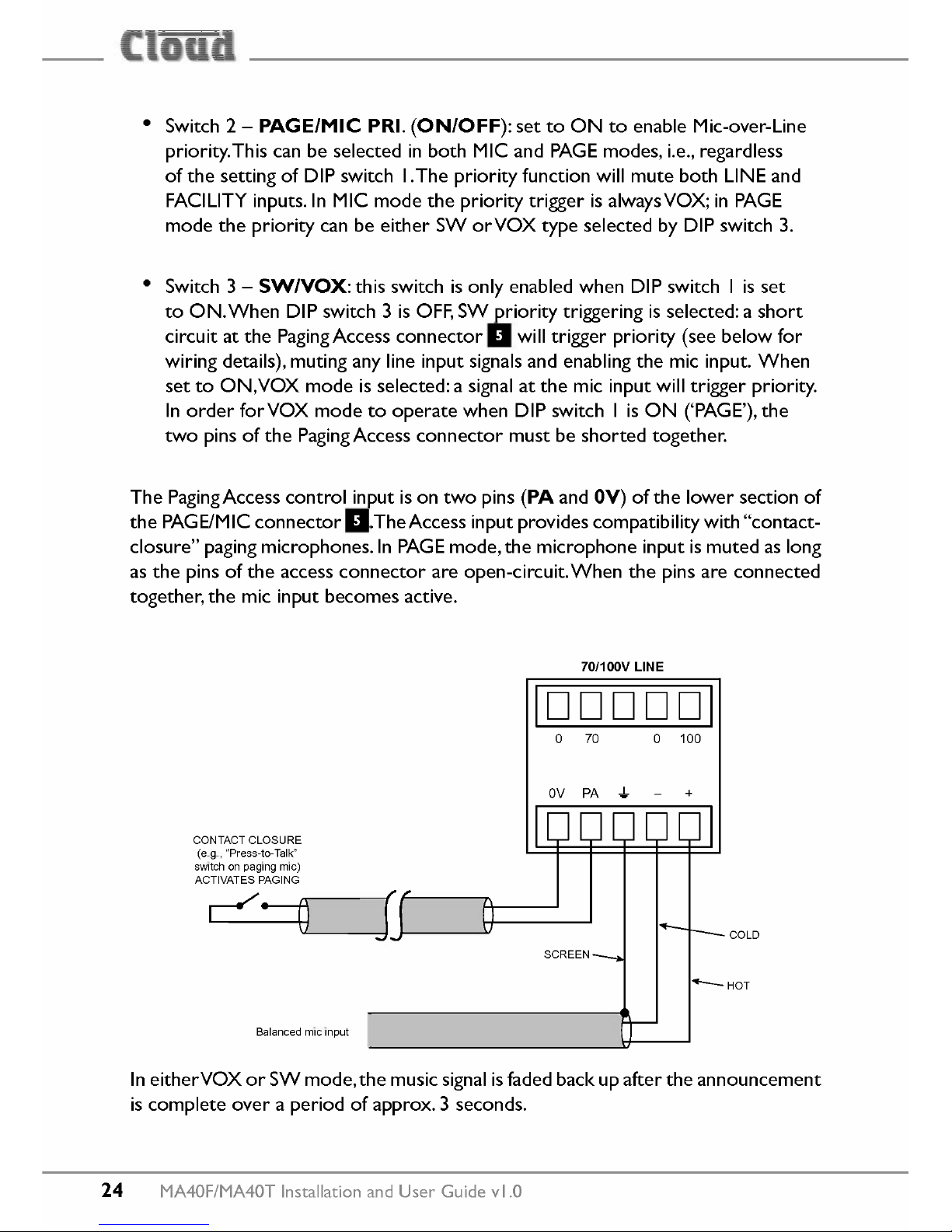
The PagingAccess control input is on two pins
(PA
and
OV)
of the lower section of
the PAGE/MIC connector I1.TheAccess input provides compatibility with "contact-
closure" paging microphones.ln PAGE mode, the microphone input is muted as long
as the pins of the access connector are open-circuit. Wh en the pins are connected
together, the mic input becomes active.
70/100V LlNE
o
70 0 100
IDDDDDI
OV PA
-!-
+
COLD
CONTACT CLOSURE
(e.g., "Press-to-Talk"
switch on paging mie)
ACTIVATES PAGING
Balanced mie input
In eitherVOX or SW mode, the music signal isfaded back up after the announcement
is complete over a period of approx. 3 seconds.
24 MA40F/MA40T Installation and User Guide vl.O
Page 25
[
-i
-ili::
_ __'5_
Output
The power amplifier stage is fully protected against
De
offset, over-current, over-
and under-voltage and is also thermally protected. Activation of the proteetion
circuitry shuts the power amplifier stage down until the fault condition clears.AII
proteetion
conditions will automatically self-clear if the amplifier is power-cycled.
A switch-on delay function mutes the output during power-up and power-down to
proteet
loudspeakers.
Lo-Z output (MA40F only)
The MA40F will deliver its rated power of 40 W into a 4 ohm load when powered
by the external
PSU
supplied with the amplifier.The maximum output power will be
reduced with lower supply voltages (please refer to MA40F/T datasheet for power
de-rating curve).
Wh en using multiple low-impedance loudspeakers (generally8ohms) with a single
amplifier, series and parallel wiring should be employed to produce a total load
impedance of not less than 4 ohms.
The low impedance output is available at the 2-pin 5 mm-pitch screw terminal
SPEAKER OUTPUT
connector on the rear panel
11.
Connecting to 100170/25V line systems (MA40T only)
The MA40T is fitted with an internal transformer enabling it to directly drive 100
Y,
70Vor 25Vline loudspeaker systems. The power amplifier stage is rated at 40 W
Loudspeakers intended for high-impedance line distribution systems usually have a
rotary switch which allows instalIers to select the power setting for each speaker
that produces the volume most appropriate for the location. InstalIers should
ensure that the total power settings of all loudspeakers connected to the MA40T in
this way does not exceed 40W
Wh en driving 100/70/25Vline loudspeaker systems there is a risk of transformer
core saturation at high levels and low frequencies, which can produce distortion.
To prevent this, the MA40F/MA40T's output stage is provided with a switchable
65
Hz
high-pass filter. We recommend that the filter is always enabled when the
amplifier is used with 100/75125Vline systems; note that Model MA40T is shipped
with the filter already enabled, but Model MA40F is shipped with the filter disabled.
If Model MA40F is used in conjunction with an external line transformer, the filter
should be enabled.
MA40F/MA40TInstallation and User Guide vl.O 25
Page 26

The filter is enabled/disabled by moving internal PCB jumper J3. See "PCB layout
diagram" on page 36 for locations of PCB jumpers.
Facility Port
MA40F and MA40T amplifiers are provided with a
FACILITY PORT
in the form
of a rear panel RJ45 connector
11.
The primary use of the Facility Port is for the
connection of an LM-2 or BT-I remote active module, but it mayalso be used to
connect RL and RSLSeries remote control plates, or as a general-purpose auxiliary
balanced input (see "Using the Facility Port as an auxiliary input" on page 31 for
more information on this application).
The active modules operate from DC power supplied by the MA40F/T.The current
consumed byeach module is minimal and in the vast majority of installations there
will be no power supply issues.
IMPORTANT:
In order for the remote control functions on an LM-2 module or
an RLlRSLSeries plate to operate,
SETTINGS
DIP switch 5
(LOCALIREMOTE)
must be set OFF ('REMOTE'). This will disable the front panel LlNE land LlNE 2
controls, and control of line level and/or LlNE I/LlNE 2 selection will be available
from the remote module or plate. DIP switch 5 should be left set to LOCAL when
a BT-I is connected to the Facility Port.
The pinout of the Facility Port connector is given in the table on the following page.
26
MA40F/MA40T Installation and User Guide vl.O
Page 27

[
-i
-ili::
_ __'5_
PIN
USE CatSCORE*
I Audio'cold' phase (-) Wh ite +
0
range
2
Audio 'hot' phase (+)
Orange
3 Priority YCA control
White + Green
4
+ ISY
Blue
5 OY
White + Blue
6 -ISY Green
7 Music level control (0 to 10Y)
White + Brown
8
Music source select control (0 to 10Y) Brown
GND GND ref for system music controls Connector shell
*
Standard wiringfor pre-made cables
RJ-45 PLUG (PIN SIOEI RJ-45 PLUG (LATCH SIOEI
RJ-45 SOCKET
MA40F/MA40T Installation and User Guide vl.O 27
Page 28

Connecting an
LM-2
or
BT-I
Mie LEVEL MUSleLEVEL
~
5 6 7 5 6 7
3
4
'~' '~'
'~"
3- -9 3- -9
0
2" '10
2' ••••10
l' I l' I
I
(/)
0 0
Q
~ PR~~ITY
•••••••••
5 6 7
Cf)
'~'
~ @
3- -9
2' '10
Mie INPUT
LlNEINPUT
I
l' I
I
0
LM-2
LM-2
STATUS
0
','
@ @
PUSH-TO-PAIR •
2s
~
5s
BT-1 el»
BT-I
The LM-2 is an aetive input module whieh allows a mierophone and a stereo line
input in a remote loeation to be eonneeted to the MA40F or MA40T. The module
also includes the funetions of a Cloud RSL-6 Remote Control Plate, whieh allows
remote control of the MA40F/MA40T's musie level and selection of Line I or Line
2 as the musie souree.
28 MA40F/MA40T Installation and User Guide vl.O
Page 29

[
-i
-ili::
_ __'5_
The BT-I is a Bluetooth remote audio input module which enables compatible
portable devices such as laptops, tab lets and smartphones to stream audio wirelessly
to the module, and thus into the audio system of the area where the module is
installed.
NOTE:
The MA40F and MA40T are only compatible with the BT-IFvariant of the
BT-I: do not attempt to connect variant BT-IE.
The LM-2 or BT-I should be connected to the MA40F/MA40T's
FACILITY PORT
using
screened
Cat 5 cable. (Note that as the cable carries analogue audio, only
screened Cat 5 should be used.) The LM-2 includes contrals for local music level
and source selection, the wiring for these functions being catered for on the Facility
Port. The maximum total Cat 5 cable length should not exceed 100 m.
LM-2:
The LM-2's upper PCB is fitted with an RJ45 connector labelled
OUTPUT.
Connect this to the
FACILITY PORT
using screened Cat 5 cable with screened
RJ45s at each end. Follow the colour coding shown in the table opposite. The metal
screening of the connectors should be bonded to the screen of the cable. Full details
can be found in the LM-2 Installation Guide.
Before the LM-2's music source and level contrals will operate, set
SETTINGS
DIP switch 5 to REMOTE (i.e., OFF. In this setting, the front panel
LlNE land
LlNE 2
contrals become inoperative. Positions 3 to 6 on the LM-2's Music Souree
switch have no function on the MA40F/MA40T; selecting these positions will
effectively mute both line inputs.
8ToI:
The BT-I has two PCBs "piggy-backed" onto the rear of the faceplate. The
RJ45 output connector (SKI) is located on the upper PCB.This should be connected
to the MA40F/MA40T's
FACILITY PORT
with
screened
Cat 5 cable and shielded
RJ45 plugs. Full details can be found in the BT-I Installation Guide.
MA40F/MA40T Installation and User Guide vl.O
29
Page 30

Connecting an RL
or
RSL Series remote control plate
MA40F and MA40T amplifiers are also compatible with standard Cloud remote
control plates of the RSLSeries (music sou ree select and level),and RL Series (level
only). The MA40F and MA40T differ from most other Cloud produets in that they
do not have a dedicated 3-pin "Remote Control" port: RL and RSL Series plates
must instead be connected to the Facility Port g.This is most easily accomplished
by using screened Cat 5 cable between the MA40F/MA40T and the remote control
plate, but only connecting the one (or two) cores concerned with the remote
control functions (see page 27), plus the screen, to the plate.
RL-1 REMOTE LEVEL CONTROL WIRING
FACILITY PORT (RJ45)
RL-1
WHITE+BROWN
Screened Cat 5 cable
IGNORE ALL
OTHER CORES
RSL-6 REMOTE SOURCE & LEVEL CONTROL WIRING
WHITE+BROWN
__ BROWN
rw:=-----J--- ~
ScreenedC8t 5 cab!e
IGNOREALL
OTHERCORES
30
MA40F/MA40T Installation and User Guide vl.O
Page 31

[
-i
-ili::
_ __'5_
Using the Facility Port as an auxiliary input
The Facility Port provides a balanced audio input. If a port is not connected to
a remote input module or remote control plate, it may be used as an additional,
balanced line input.The signal applied at the FacilityPort ismixed with the other inputs
(Line I, LlNE 2 and MIC), but has no independent level control on the amplifier; the
signal level must be adjusted at the source. If Mic-over-Line priority is enabled (see
"Paging control and mic priority" on page 23), a line input at the Facility Port will
be muted in the same way as LlNE land LlNE 2.
Connect an external balanced souree to the Facility Port as shown below:
BALANCED
OUTPUT (e.q., XLR)
~ -r-
FACILITY PORT (RJ45)
EL~~-===~~------------------~~ -HD
001(+)
coId(-)
Twin-core screened cable
An unbalanced souree mayalso be connected; the use of balancing transformers is
recommended.
Control of musie
souree
and level via external DC
It may be necessary in some installations to adjust the music level and select music
source from an external control system (e.g., Crestron, AMX, etc.). If the Facility
Port is not required for a remote input module or control plate, it may be used to
receive DC voltages from the external system to effect these adjustments.
Both music souree selection and level can be controlled with a DC voltage of 0 to
+IOY.Refer to the Facility Port pinout at page 27: music souree selection (restricted
to LlNE I/LiNE 2 selection in the case of the MA40F/MA40T) is controlled by
applying a DC voltage to pin 8, and music level by a DC voltage at pin 7.The 0 V
reference for both contrals is via the screen of the shielded RJ4Sconnector.
MA40F/MA40T Installation and User Guide vl.O
31
Page 32
CONTROL
SYSTEM
FACLITYPORT
SOURCE CONTROL
t-....••
i------::v----ta
01
02
03
04
05
06
4k7 10k
MUSle SOURCE
SELECT
'>, ~
I---- ••.;-.;,~
+12V
/
CONECTOR
SHELL
ov
MUSICVCA
MA40F/MA40T
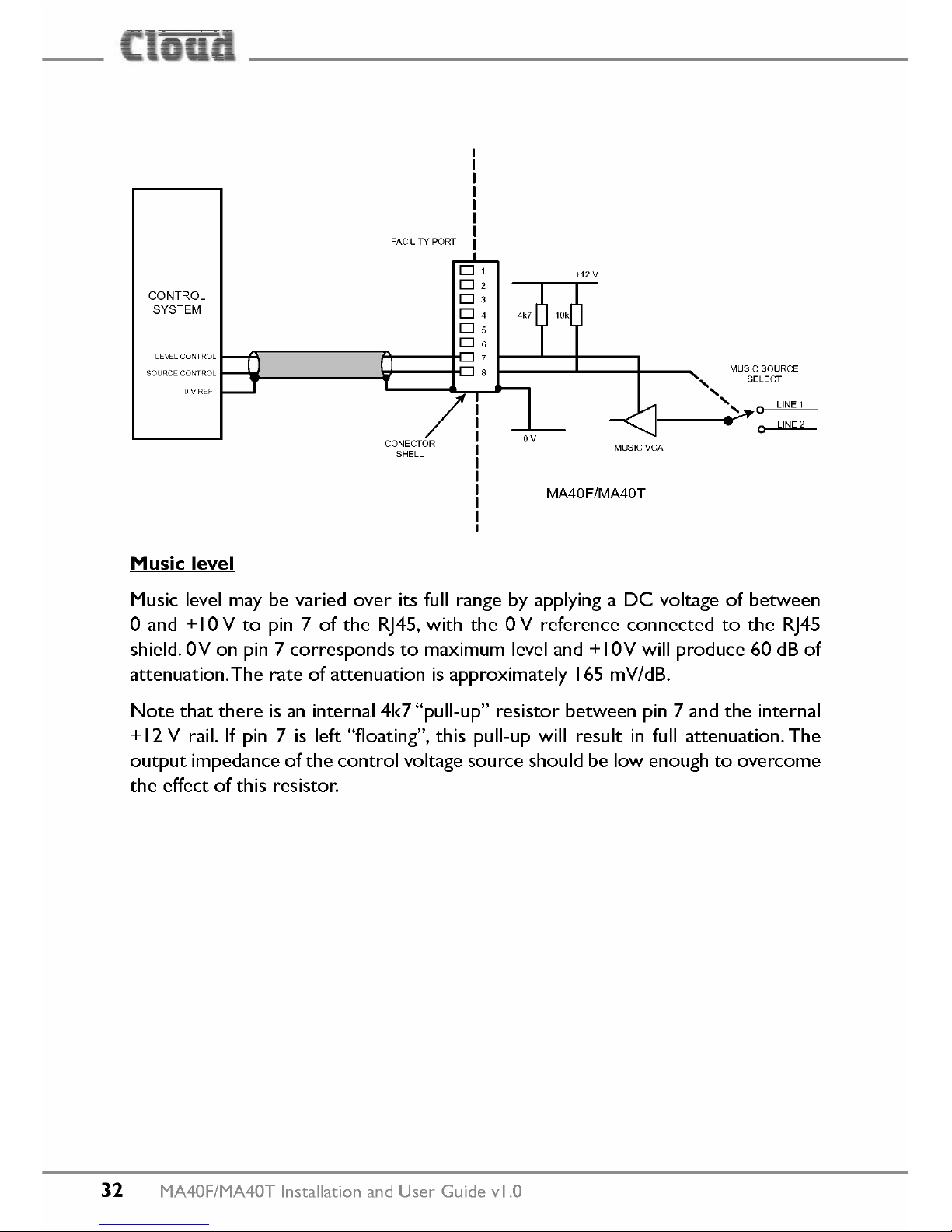
Music level
Music level may be varied over its full range by applying a
De
voltage of between
o
and+I0 V to pin 7 of the RJ45,with the 0 V reference connected to the RJ45
shield. OV on pin7corresponds to maximum level and+IOV will produce
60
dB of
attenuation.The rate of attenuation is approximately
165
mV/dB.
Note that there is an internal
4k7
"pull-up" resistor between pin7and the internal
+
12
V rail. If pin7is left "floating", this pull-up will result in full attenuation. The
output impedance of the control voltage
souree
should be low enough to overcome
the effect of this resistor.
32
MA40F/MA40T
Installation and User Guide vl.O
Page 33
[
-i
-ili::
_ __'5_
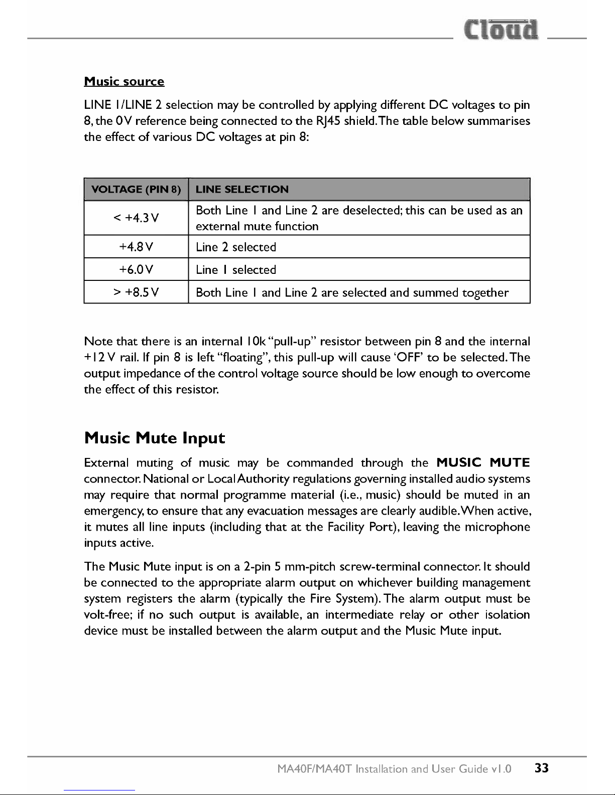
Music souree
LlNE I/LiNE 2 selection may be controlled by applying different DC voltages to pin
8, the OV reference being connected to the RJ45 shield.The table below summarises
the effect of various DC voltages at pin 8:
VOLTAGE (PIN
8)
LlNE SELECTION
< +4.3V
Both Line land Line 2 are deselected; this can be used as an
external mute function
+4.8V
Line 2 selected
+6.0V
Line I selected
> +8.5V
Both Line land Line 2 are selected and summed together
Note that there is an internal 10k "pull-up" resistor between pin 8 and the internal
+ 12V rail. If pin 8 is left "floating", this pull-up will cause 'OFF' to be selected. The
output impedance of the control voltage souree should be low enough to overcome
the effect of this resistor.
Music Mute Input
External muting of music may be commanded through the
MUSle MUTE
connector. National or LocalAuthority regulations governing installed audio systems
may require that normal programme material (i.e., music) should be muted in an
emergency, to ensure that any evacuation messages are clearly audible.When active,
it mutes all line inputs (including that at the Facility Port), leaving the microphone
inputs active.
The Music Mute input is on a 2-pin 5 mm-pitch screw-terminal connector.lt should
be connected to the appropriate alarm output on whichever building management
system registers the alarm (typically the Fire System). The alarm output must be
volt-free; if no such output is available, an intermediate relay or other isolation
device must be installed between the alarm output and the Music Mute input.
MA40F/MA40T Installation and User Guide vl.O 33
Page 34
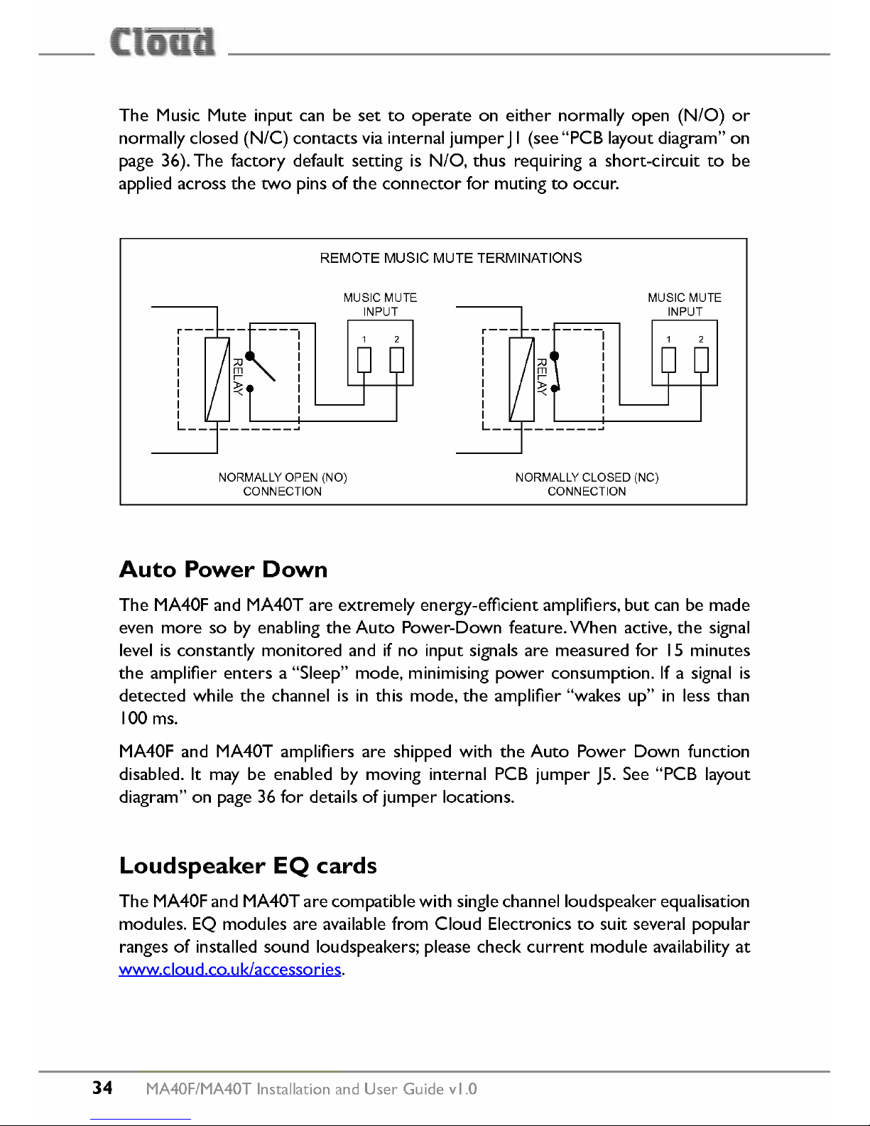
The Music Mute input can be set to operate on either normally open (N/O) or
normally closed
(N/C)
contacts via internal jumperJI (see "PCB layout diagram" on
page 36). The factory default setting is NIO, thus requiring a short-circuit to be
applied across the two pins of the connector for muting to occur.
REMOTE MUSle MUTE TERMINATIONS
MUSIC MUTE
INPUT
MUSIC MUTE
INPUT
NORMALLY OPEN (NO)
CONNECTION
NORMALLY CLOSED (NC)
CONNECTION
Auto Power Down
The MA40F and MA40T are extremely energy-efficient amplifiers, but can be made
even more so by enabling the Auto Power-Down feature. When active, the signal
level is constantly monitored and if no input signals are measured for
15
minutes
the amplifier enters a "Sleep" mode, minimising power consumption. If a signal is
detected while the channel is in this mode, the amplifier "wakes up" in less than
100 ms.
MA40F and MA40T amplifiers are shipped with the Auto Power Down function
disabled. It may be enabled by moving internal PCB jumper J5. See "PCB layout
diagram" on page 36 for details of jumper locations.
Loudspeaker EQ
cards
The MA40F and MA40T are compatible with single channelloudspeaker equalisation
modules. EQ modules are available from Cloud Electronics to suit several popular
ranges of installed sound loudspeakers; please check current module availability at
www.cloud.co.uk/accessories.
34
MA40F/MA40T Installation and User Guide vl.O
Page 35
[
-i
-ili::
_ __'5_
Installation Instructions
Refer to the PCB layout diagram (see "PCB layout diagram" on page 36) for the
location of the EQ module connector and its associated bypass jumper J2.
To install an EQ module, proceed as follows:
I. Isolate the amplifier from its DC power source.
2. Remove the screws securing the top cover: there are two on the top and two
on each side. Remove the cover.
3. Remove jumper J2.We recommend "stowing" it on one of the header pins in
case it ever needs to be replaced.
4. Plug the loudspeaker equalisation module into its 12-pin connector CON I;
note that the connector has two notches on one side which engage with lugs
on the module's mating connector to ensure correct orientation.
S. Replace the top cover.
MA40F/MA40T Installation and User Guide vl.O 35
Page 36
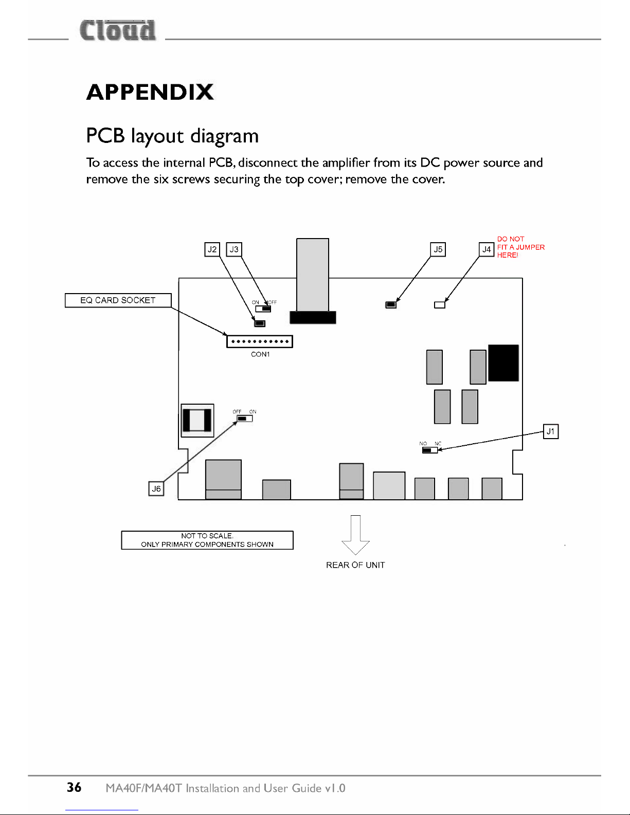
APPENDIX
PCB layout diagram
To access the internal PCB, disconnect the amplifier from its DC power souree and
remove the six screws securing the top cover; remove the cover.
EQ CARD SOCKET
OFF ON
-
J6
NOTTO SCALE.
ONLY PRIMARY COMPONENTS SHOWN
DO NOT
J4 FIT A JUMPER
HERE!
o
0
00
REAROF UNIT
36 MA40F/MA40T Installation and User Guide vl.O
Page 37
[
-i
-ili::
_ __'5_
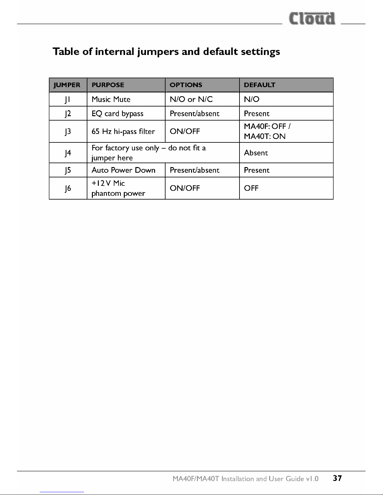
Table of internal jumpers and default settings
JUMPER
PURPOSE OPTIONS DEFAULT
JI
Musie Mute N/O or N/C N/O
J2
EQ eard bypass Present/absent Present
J3
65 Hz hi-pass filter ON/OFF
MA40F:OFF
I
MA40T:ON
J4
For faetory use only - do not fit a
Absent
jumper here
J5
Auto Power Down Present/absent Present
J6
+12V Mie
ON/OFF OFF
phantom power
MA40F/MA40T Installation and User Guide vl.O 37
Page 38
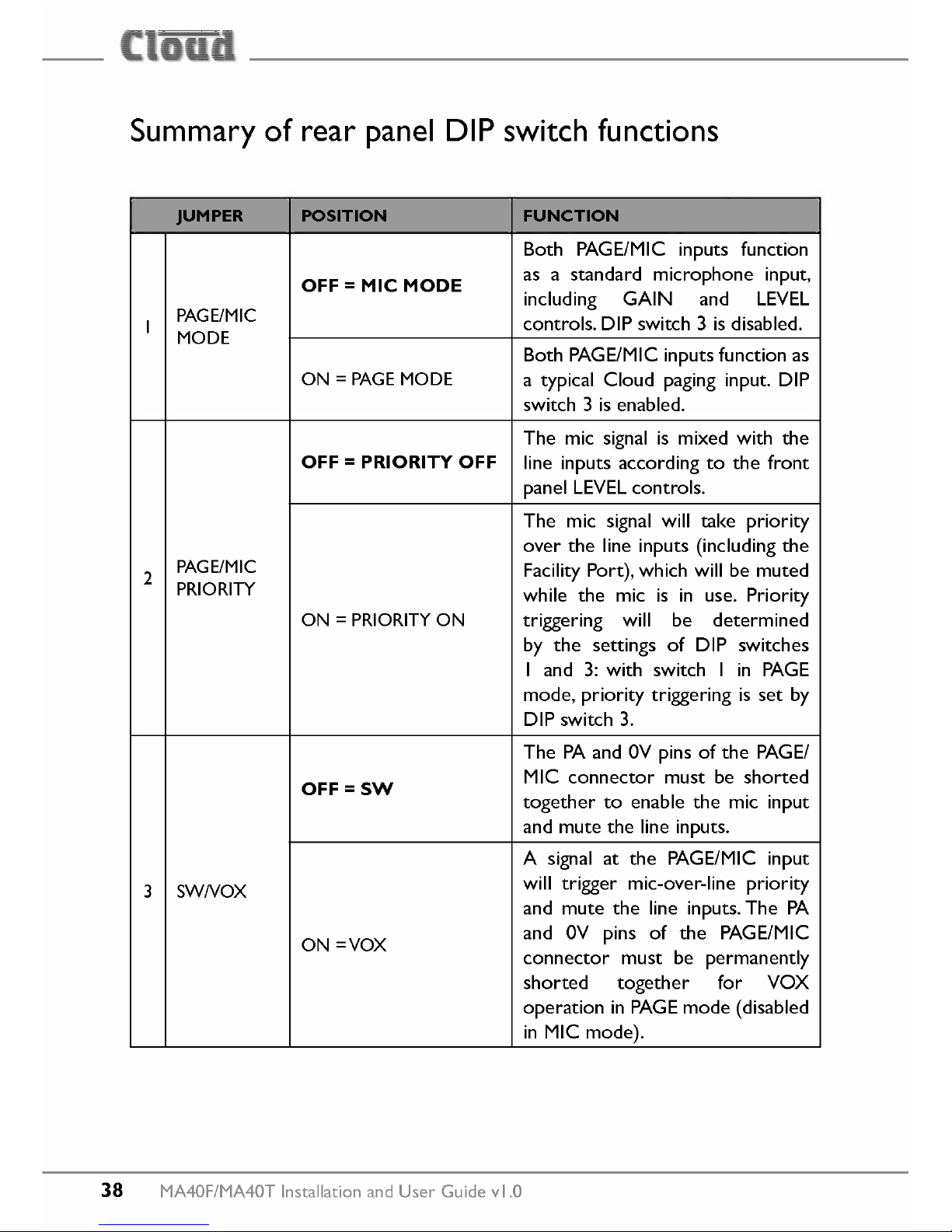
Summary of rear panel DIP switch functions
JUMPER
POSITION FUNCTION
Both PAGE/MIC inputs function
OFF = Mie MODE
as a standard microphone input,
including GAIN and LEVEL
I
PAGE/MIC
controls.DIP switch 3 isdisabled.
MODE
Both PAGE/MICinputsfunction as
ON = PAGEMODE
a typical Cloud paginginput. DIP
switch 3 isenabled.
The mic signalis mixed with the
OFF = PRIORITY OFF
line inputs accordingto the front
panelLEVELcontrols.
The mic signalwill take priority
over the line inputs (includingthe
2
PAGE/MIC
FacilityPort),which will be muted
PRIORITY
while the mic is in use. Priority
ON = PRIORITYON
triggering will be determined
by the settings of DIP switches
I and 3: with switch I in PAGE
mode,priority triggering is set by
DIPswitch 3.
The PAand OVpins of the PAGE/
OFF=SW
MIC connector must be shorted
together to enablethe mic input
andmutethe line inputs.
A signal at the PAGE/MICinput
3 SWNOX
will trigger mic-over-line priority
and mute the line inputs.The PA
ON =VOX
and OV pins of the PAGE/MIC
connector must be permanently
shorted together for VOX
operation in PAGEmode (disabled
in MIC mode).
38
MA40F/MA40TInstallationandUserGuidevl.O
Page 39
[
-i
-ili::
_ __'5_
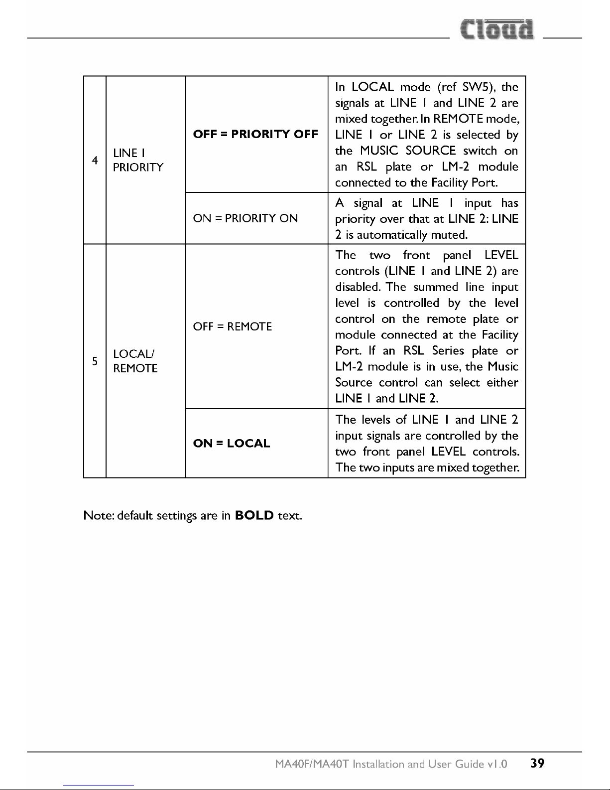
4
LlNEI
PRIORITY
OFF=PRIORITY OFF
ON = PRIORITY ON
OFF = REMOTE
ON=LOCAL
LOCAL/
REMOTE
Note: default settings are in
BOLO
text.
5
In LOCAL mode (ref SWS), the
signals at LlNE land LlNE 2 are
mixed together.ln REMOTE mode,
LlNE I or LlNE 2 is selected by
the MUSIC SOURCE switch on
an RSL plate or LM-2 module
connected to the Facility Port.
A signal at LlNE I input has
priority over that at LlNE 2: LlNE
2 is automatically muted.
The two front panel LEVEL
controls (LiNE land LlNE 2) are
disabled. The summed line input
level is controlled by the level
control on the remote plate or
module connected at the Facility
Port. If an RSL Series plate or
LM-2 module is in use, the Music
Souree control can select either
LlNE land LlNE 2.
The levels of LlNE land LlNE 2
input signals are controlled by the
two front panel LEVEL controls.
The two inputs are mixed together.
MA40F/MA40T Installation and User Guide vl.O
39
Page 40
EMC considerations
MA40F and MA40T amplifiers fully conform to the relevant electromagnetic
compatibility (EMC) standards and are technically weil behaved. You should
experience no problems interfacing units to other items of equipment and under
normal circumstances, no special precautions need to be taken. If the unit is to
be used in close proximity to potential sourees of HF disturbance such as high
power communication transmitters, radar stations and the like, it is suggested that
input signal leads be kept as short as possible.Always use balanced interconnections
wherever possible. We recommend that the MA40F/MA40T amplifier is not located
in close proximity to a high-power amplifier or similar item of equipment, which
may radiate astrong magnetic field from its power transformer.
Earthing
Wh en several mains powered units are connected together via their signal cab les,
there is a risk of one or more earth loops which may cause an audible hum on
the system even with the gain contrals set to minimum. The 0 V rail of an MA40F/
MA40T amplifier is directly coupled to the chassis ground. No interconnection
problems should be encountered, but ifthere is any hum or other extraneous noise
when source equipment is connected, the situation can generally be remedied by
observing the following guidelines:
I. Always connect sourees using balanced connections wherever possible. Note
th at, for EMC reasons, the cable screen should be connected at both ends.
2. Use audio isolating transformers (readily available from trade suppliers) at the
inputs if necessary. These will ensure that the amplifier is electrically isolated
from the source equipment.
3. The signal source units should be located as close as practical to the amplifier.
The metal housings of the various units should not be electrically connected.
Try to ensure that all interconnected units, including power amplifiers, are
connected to a common power source to ensure a common ground is provided.
40
MA40F/MA40TInstallationand User Guide vl.O
Page 41
[
-i
-ili::
_ __'5_
Technical specifications
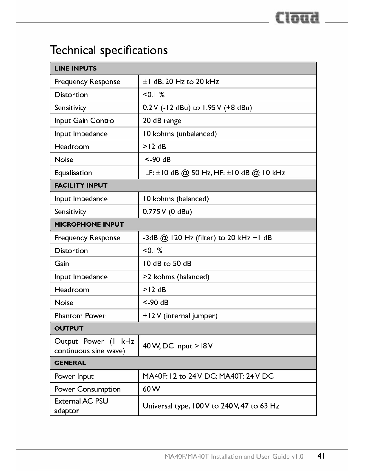
LlNE INPUTS
Frequency Response ± I dB,20 Hz to 20 kHz
Distortion
<0.1 %
Sensitivity 0.2V (-12 dBu) to 1.95V (+8 dBu)
Input Gain Control 20 dB range
Input Impedance 10kohms (unbalanced)
Headroom
>12 dB
Noise
<-90 dB
Equalisation LF:±IO dB@ 50 Hz,HF:±IO dB@ 10 kHz
FACILITYINPUT
Input Impedance 10kohms (balanced)
Sensitivity 0.775 V (0 dBu)
MICROPHONEINPUT
Frequency Response -3dB @ 120 Hz (filter) to 20 kHz ± I dB
Distortion
<0.1%
Gain 10 dB to 50 dB
Input Impedance >2 kohms (balanced)
Headroom
>12 dB
Noise
<-90 dB
Phantom Power + 12V (internal jumper)
OUTPUT
Output Power (I kHz
40W,DC input>18V
continuous sine wave)
GENERAL
Power Input
MA40F: 12 to 24 V DC; MA40T: 24 V DC
Power Consumption 60W
External AC PSU
Universal type, IOOVto 240 V,47 to 63 Hz
adaptor
MA40F/MA40T Installation and User Guide vl.O
41
Page 42

Fixed level signal limiter
Protection against De, PSU overcurrent, amplifier
Amplifier Protection overcurrent, over-temperature, supply voltage under/
over-voltage
Resettable internal breaker (no fuses)
Net
220 mm x 41 mm x 144.5 mm
8.7" x 1.6" x 5.7"
MA40F
Shipping
290 mm x 160 mm x 210 mm
Dimensions
I lA" x 6.3" x 8.3"
(w
x h x d)
Net
303 mm x 41 mm x 144.5 mm
I 1.9" x 1.6" x 5.7"
MA40T
Shipping
290 mm 160 mm x 380 mm
I lA" x 6.3" x 15"
Net 750 g
MA40F
Weight
Shipping 1.0 kg
Net 1.65 kg
MA40T
Shipping 1.8 kg
42
MA40F/MA40TInstallationand User Guide vl.O
Page 43

[
-i
-ili::
_ __'5_
MA40F/MA40T Installation and User Guide vl.O
43
Page 44

www.cloud.co.uk
MADEIN BRITAINII
www.cloudusa.pro
 Loading...