

Page 1
MA40E Installation and User Guide v1.0
1
MA40E
Mini Amplifier
Installation and User Guide
Page 2
MA40E Installation and User Guide v1.0
2
WARNING:
To reduce the risk of fire or electric shock, do not expose this appliance to rain or
moisture.
WARNING: SHOCK HAZARD – DO NOT OPEN
AVIS: RISQUE DE CHOC ELECTRIQUE – NE PAS
OUVRIR
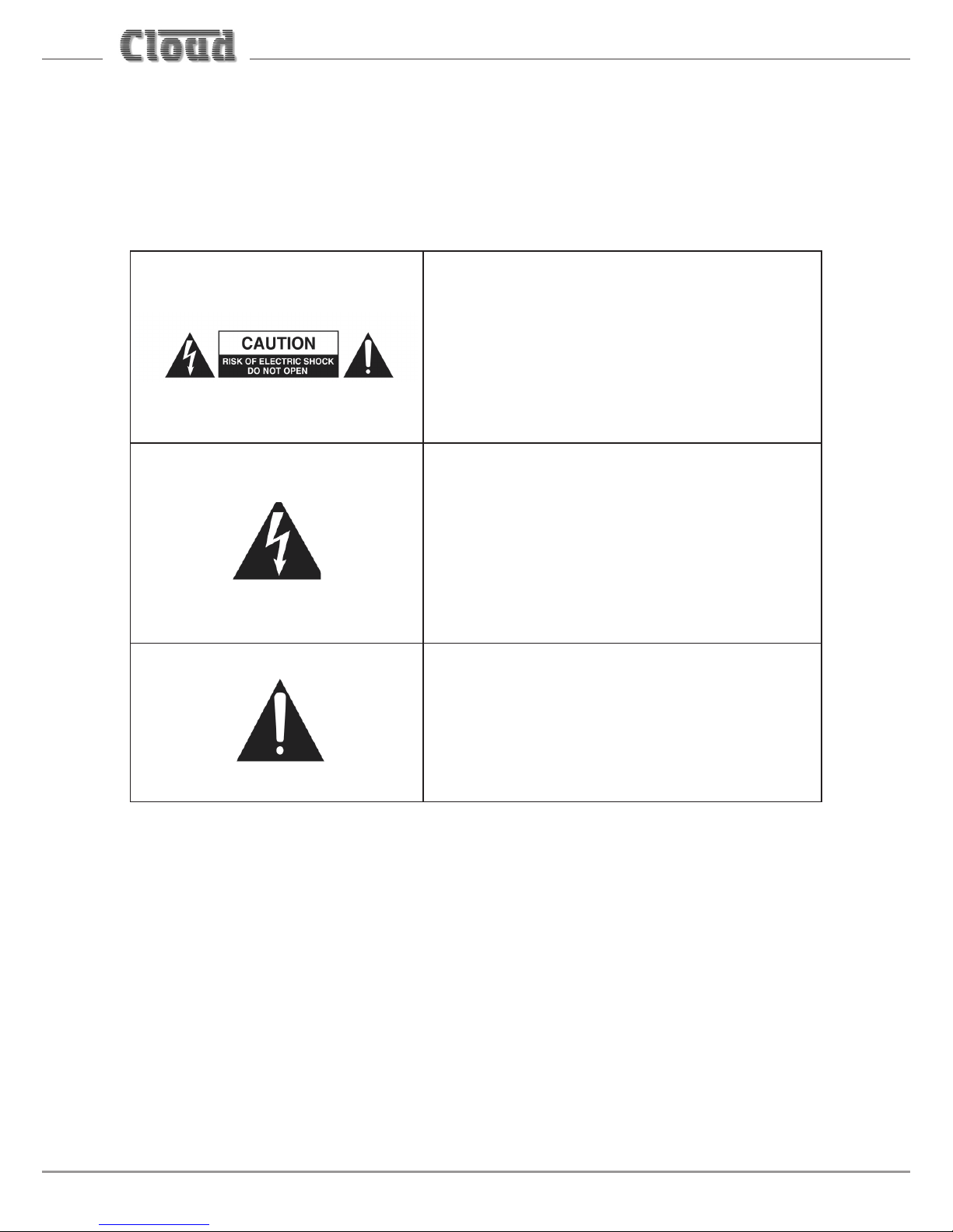
The lightning flash with the arrowhead
symbol within an equilateral triangle, is
intended to alert you to the presence of
uninsulated dangerous voltages within the
product’s enclosure that may be of sufficient
magnitude to constitute a risk of electric
shock.
The exclamation point within an equilateral
triangle is intended to alert the user to
the presence of important operating and
maintenance (servicing) instructions in the
literature accompanying the appliance.
Page 3

MA40E Installation and User Guide v1.0
3
IMPORTANT SAFETY INSTRUCTIONS
1. Read these Instructions.
2. Keep these Instructions.
3. Heed all Warnings.
4. Follow all Instructions.
5. Do not use this apparatus near water.
6. Clean only with a dry cloth.
7. Do not block any ventilation openings. Install in accordance with the
manufacturer’s instructions.
8. Do not install near any heat sources such as radiators, heat registers, stoves or
other apparatus (including amplifiers) that produce heat.
9. Do not defeat the safety purpose of the polarized or grounding - type plug. A
polarized plug has two blades with one wider than the other. A grounding type
plug has two blades and a third grounding prong. The wide blade or the third
prong are provided for your safety. When the provided plug does not fit into
your outlet, consult an electrician for replacement of the obsolete outlet.
10. Protect the power cord from being walked on or pinched particularly at plugs,
convenience receptacles, and the point where they exit from the apparatus.
11. Only use attachments/accessories specified by the manufacturer.
12. Use only with the cart, stand, tripod, bracket or table specified by
the manufacturer or sold with the apparatus, when a cart is used,
use caution when moving the cart/apparatus combination to avoid
injury from tip-over.
13. Unplug this apparatus during lightning storms or when unused for long periods
of time.
14. Refer all servicing to qualified service personnel. Servicing is required when the
apparatus has been damaged in any way, such as power-supply cord or plug is
damaged, liquid has been spilled or objects have fallen into the apparatus, the
apparatus has been exposed to rain or moisture, does not operate normally, or
has been dropped.
Page 4
MA40E Installation and User Guide v1.0
4
Do not expose the apparatus to dripping or splashing, and ensure that
no objects filled with water, such as vases, are placed on the apparatus.
L’appareil ne doit pas être exposé aux écoulements ou aux éclaboussures et aucun
objet ne contenant de liquide, tel qu’un vase, ne doit être placé sur l’objet.
The mains plug is used as the disconnect device and it should remain
readily accessible during intended use. In order to isolate the apparatus
from the mains, the mains plug should be completely removed from the
mains outlet socket.
La prise du secteur ne doit pas être obstruée ou doit être facilement accessible
pendant son utilisation. Pour être complètement déconnecté de l’alimentation
d’entrée, la prise doit être débranchée du secteur.
Terminals marked with the symbol may use Class 2 Wiring, but
voltages at these terminals may be of sufficient magnitude to
constitute a risk of electric shock. The external wiring connected to
these terminals requires installation by an instructed person or the use
of pre-made leads or cords.
Page 5

MA40E Installation and User Guide v1.0
5
Contents
IMPORTANT SAFETY INSTRUCTIONS ................................................................. 3
SAFETY INFORMATION ......................................................................................... 7
Safety Notes regarding Installation ..........................................................................7
Conformities .................................................................................................................... 7
RoHS and WEEE declaration .................................................................................... 8
Safety Considerations and Information ................................................................... 9
Mains Fuse ................................................................................................................... 9
Servicing ........................................................................................................................9
OVERVIEW .............................................................................................................10
Introduction ...................................................................................................................10
Applicable Model ..........................................................................................................10
MA40E main features ..................................................................................................11
What’s in the Box .........................................................................................................12
BLOCK DIAGRAM .................................................................................................. 13
FRONT PANEL DESCRIPTION .............................................................................14
REAR PANEL DESCRIPTION ................................................................................. 15
INSTALLATION ......................................................................................................16
Mechanical .....................................................................................................................16
Ventilation ......................................................................................................................17
Connections and adjustments ..................................................................................18
Line inputs ..................................................................................................................18
Sensitivity & Gain Control ..................................................................................19
Music Level and EQ control ................................................................................19
Line 1 Priority ..........................................................................................................19
Output .........................................................................................................................20
Connecting to 100/70/25 V line systems ......................................................20
Facility Port ................................................................................................................21
Connecting an LM-2 or BT-1 ..............................................................................23
Connecting an RL or RSL Series remote control plate................................25
Using the Facility Port as an auxiliary input .................................................26
Music Mute Input .....................................................................................................26
Auto Power Down ....................................................................................................27
Page 6

MA40E Installation and User Guide v1.0
6
ETHERNET CONTROL OF THE MA40E ..............................................................28
OS and Browser compatibility .................................................................................28
Checking browser compatibility ..............................................................................28
Configuring the network ............................................................................................28
MA40E browser control ..............................................................................................33
Zone 1 page ................................................................................................................33
Input Routing tab ...................................................................................................35
Room EQ tab ...........................................................................................................36
Front Panel EQ tab ................................................................................................38
Speaker EQ tab .......................................................................................................38
Output tab ...............................................................................................................41
Configuration menu .....................................................................................................42
User Security .............................................................................................................43
Change Installer PIN ................................................................................................47
Labelling ......................................................................................................................48
General Settings .......................................................................................................49
Network ......................................................................................................................51
Save/Restore ..............................................................................................................53
Device Info ..................................................................................................................55
MA40E SERIAL CONTROL ...................................................................................56
Abridged command set ..............................................................................................57
Examples .....................................................................................................................58
Using the MA40E as an Ethernet-to-serial bridge ..............................................60
APPENDIX ...............................................................................................................61
PCB layout diagram .....................................................................................................61
Table of internal jumpers and default settings ...............................................62
Summary of rear panel DIP switch functions ......................................................63
Table of factory settings .............................................................................................64
EMC considerations .....................................................................................................65
Earthing ...........................................................................................................................65
Technical specifications ..............................................................................................66
Page 7

MA40E Installation and User Guide v1.0
7
SAFETY INFORMATION
Safety Notes regarding Installation
• Do not expose the unit to water or moisture.
• Do not expose the unit to naked flames.
• Do not block or restrict any air vent.
• Do not operate the unit in ambient temperatures above 35°C.
• Do not touch any part or terminal carrying the hazardous live symbol while
power is supplied to the unit.
• Do not perform any internal adjustments unless you are qualified to do so and
fully understand the hazards associated with mains-operated equipment.
• The unit has no user-serviceable parts. Refer servicing to qualified service
personnel.
• If the moulded plug is cut off the AC power lead for any reason, the discarded
plug is a potential hazard and should be disposed of in a responsible manner.
Conformities
This product conforms to the following European EMC Standards:
BS EN 55103-1:2009
BS EN 55103-2:2009
This product has been tested for use in commercial and light industrial environments.
If the unit is used in controlled EMC environments, the urban outdoors, heavy
industrial environments or close to railways, transmitters, overhead power lines,
etc., the performance of the unit may be degraded.
The product conforms to the following European electrical safety standards:
BS EN 60065:2002 (+A2:2010)
UL60065
This product is compliant with the relevant provisions of:
Energy Star® Eligibility Criteria Ver 3.0 for Audio-Video products.
Page 8

MA40E Installation and User Guide v1.0
8
RoHS and WEEE declaration
Cloud Electronics Limited manages its business and collaborates with its suppliers
to comply with the European Union restriction of the use of certain hazardous
substances in electrical and electronic equipment, RoHS Directive (2002/95/EC),
that came into force on 1st July 2006, and similar restrictions in other jurisdictions.
The “crossed out wheelie bin” symbol on the product and represented
above is there to remind users of the obligation of selective collection
of waste. This label is applied to various products to indicate that the
product is not to be thrown away as unsorted municipal waste. At the
end of life, dispose of this product by returning it to the point of sale or
to your local municipal collection point for recycling of electric and electronic
devices.
Customer participation is important to minimize the potential effects on the
environment and human health that can result from hazardous substances that
may be contained in this product.
Please dispose of this product and its packaging in accordance with local and national
disposal regulations, including those governing the recovery and recycling of waste
electrical and electronic equipment. Contact your local waste administration, waste
collection company or dealer.
Page 9

MA40E Installation and User Guide v1.0
9
Safety Considerations and Information
The MA40E is powered by an external DC supply. A separate Power Supply
Unit (PSU) is supplied with the amplifier. The PSU must be earthed. Ensure that
the mains power supply provides an effective earth connection using a threewire termination.
Mains Fuse
The PSU is a sealed unit and contains no user-replaceable fuses. Mains over-current
protection is provided by the fuse in the AC mains plug, which should be rated
at 5 A.
Servicing
The unit contains no user serviceable parts. Refer servicing to qualified service
personnel. Do not perform servicing unless you are qualified to do so. Disconnect
the power cable from the unit before removing the top panel and do not make any
internal adjustments with the unit switched on. Only reassemble the unit using
either the original bolts/screws, or ones identical to the original parts.
Page 10

MA40E Installation and User Guide v1.0
10
OVERVIEW
Introduction
The MA40E is a very compact stereo amplifier of advanced design, intended
for integration into audio and AV systems where de-centralised installation is
advantageous. It may be considered an “install-and-forget” component, and is
small enough to be fitted into a wall or ceiling void, or in any convenient location
adjacent to projectors, flat screen displays or loudspeakers, for example. It is highly
suitable for use with in-store digital signage, gallery and museum exhibits and in
fixed or mobile tour guide systems.
The MA40E can deliver 20 W per channel into a 4 ohm load. There are two unbalanced
inputs for stereo line level signals (typically music sources). Front panel preset-type
controls are provided for music level and music EQ. There are also various preset
adjustments, configuration DIP switches on the rear panel and jumpers mounted
internally on the main PCB. A remote input module or remote level control can
be wired to the amplifier’s Facility Port, which can also be used as an additional
line input. An Ethernet port provides extensive remote configuration and control
options using any compatible network device with a standard web browser. The
MA40E may also be fully controlled using RS-232 commands.
The MA40E will operate “out of the box” in its basic configuration: the simple set
of manual controls and configuration options makes it quick and easy to integrate
into any audio system. Greatly enhanced control and configuration can be achieved
through the internal web server, including control of the amplifier’s DSP section.
Applicable Model
This Installation Guide describes the installation and operation of the following
model only:
• Cloud MA40E 20 W/ch stereo amplifier for 4 ohm loudspeakers.
NOTE: Amplifier models MA40, MA40F and MA40T are NOT covered by this Guide,
and when installing any of these models, reference should only be made to the
Guides specific to them.
Page 11

MA40E Installation and User Guide v1.0
11
MA40E main features
• Internal web server for simple and secure setup and control from any location
• Two (unbalanced) stereo line inputs with individual gain trims
• Front panel per-channel control of level
• Front panel HF & LF EQ controls
• Selectable LINE 1-over-LINE 2 priority
• Extensive set of DSP functions for advanced configuration
• Front panel controls can be disabled when browser control is in use
• Facility port for connection of LM-2 or BT-1 remote mic/line input modules
via screened Cat 5 cable; also allows remote control of music level and source
• 2 x 20 W (into 4 ohms) power amplifiers
• Music Mute control input (N/O or N/C) for interface to emergency system
• Power amplifier fully protected by open and short circuit load detection,
temperature sensing, power rail monitoring
• RS-232 port for full serial control; serial commands may also be sent via
Ethernet
• Automatic power-down function (user-selectable)
• Less than 3 W power consumption in sleep mode
• Convection cooled – silent in operation
• PSU meets US DoE Level VI energy requirements
• Power requirements: 12 to 24 V DC, 60 W
• Universal AC adaptor included (both models), operates from 100 to 240 V AC
Available Options:
• LM-2 remote mic/line input module with music volume control
• BT-1 Bluetooth wireless audio input module
Page 12

MA40E Installation and User Guide v1.0
12
What’s in the Box
Please check the shipping carton for damage before opening. If there is damage,
please contact your Cloud agent and the shippers.
The packing carton should contain the following items:
• MA40E amplifier
• External PSU (AC mains adaptor)
• IEC mains lead (AC cord) with moulded plug appropriate to the territory
• Set of mating plug-in screw-terminal connectors
• Set of four self-adhesive polyurethane feet
• This manual
Page 13
MA40E Installation and User Guide v1.0
13
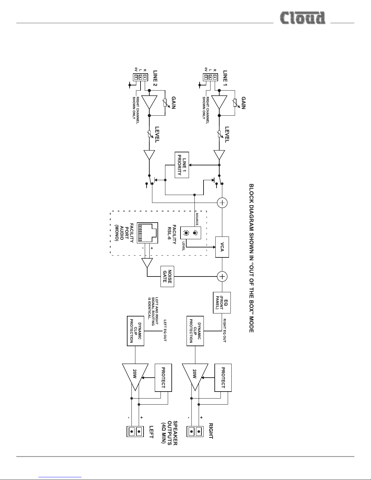
BLOCK DIAGRAM
Page 14
MA40E Installation and User Guide v1.0
14
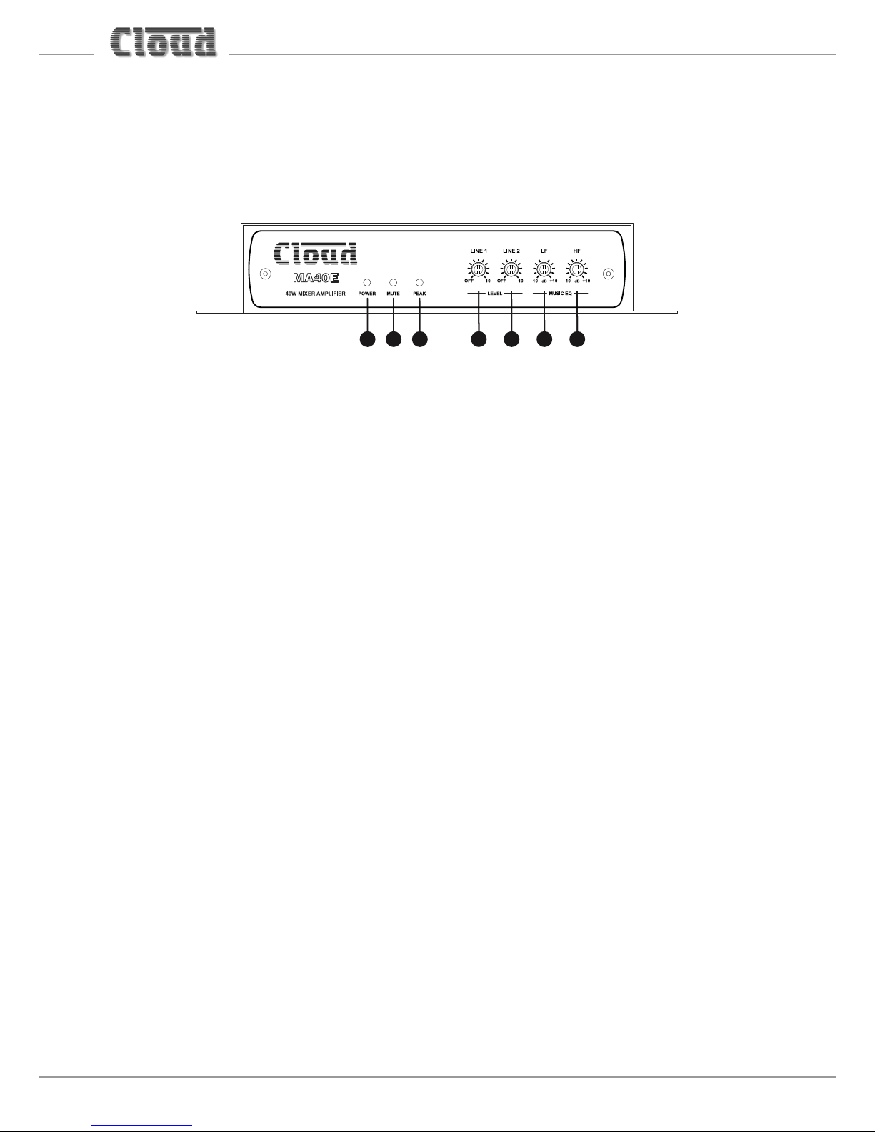
FRONT PANEL DESCRIPTION
5 6 7 1 2 3 4
LEVEL controls:
1. LINE 1 – adjusts volume of signal at the LINE 1 input
2. LINE 2 – adjusts volume of signal at the LINE 2 input
EQ controls:
3. LF – LF EQ adjustment of music channel: +/-10 dB @ 50 Hz
4. HF – HF EQ adjustment of music channel: +/-10 dB @ 10 kHz
5. POWER – bi-colour LED: illuminates green when the amplifier is active and red
when the amplifier is in Automatic Power Down mode
6. MUTE – red LED: illuminates when the MUSIC MUTE function is active
7. PEAK – red LED: illuminates if the amplifier’s dynamic clip protection becomes
active
Page 15
MA40E Installation and User Guide v1.0
15
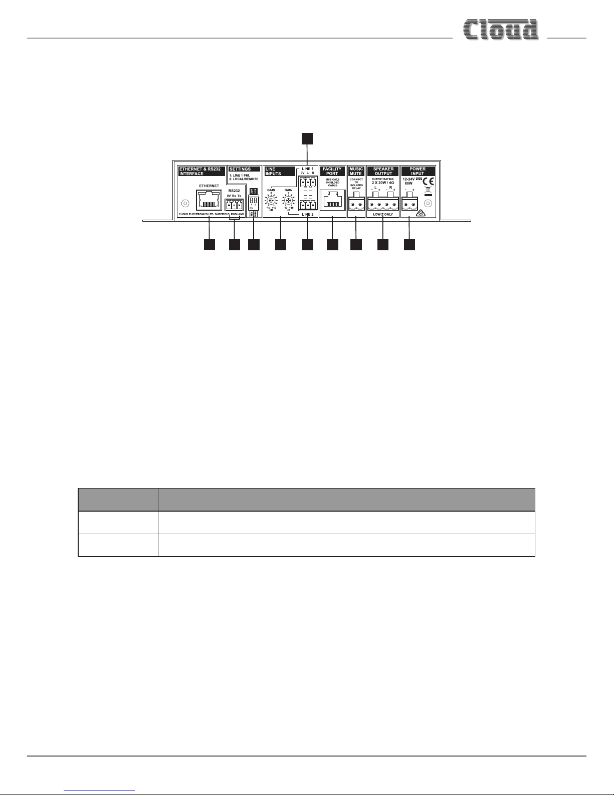
REAR PANEL DESCRIPTION
1 3 4 95268
7
1
1. LINE 1 and LINE 2 – stereo line inputs for music sources (unbalanced)
2. GAIN – preset level trim controls (+/-10 dB) for each line input
3. FACILITY PORT – RJ45 socket for connection of remote input/control modules
such as the LM-2 and BT-1; it is also possible to connect an RL-1 or RSL-6
remote control plate to this port
4. SPEAKER OUTPUT – two speaker outputs for low-impedance circuits
5. MUSIC MUTE – connect to external N/O or N/C contacts for remote muting
of music sources
6. SETTINGS – two-pole DIP switch for setting various amplifier configurations:
SWITCH FUNCTION
1 Enables LINE 1-over-LINE 2 priority
2 Enables remote control functions of Facility Port
See page 62 in the Appendix section for full details.
7. ETHERNET – standard RJ45 network port for connection to computer or other
device; allows access to browser pages for remote control and configuration
8. RS232 – bidirectional serial control port
9. POWER INPUT – connect external DC power here: the MA40E requires 12 to
24 V at 60 W
Page 16

MA40E Installation and User Guide v1.0
16
INSTALLATION
Mechanical
The compact size and light weight of the MA40E combined with its high energy
efficiency allows it to be installed in almost any location. It can be easily placed in
ceiling or wall voids, or fitted to the rear of display screens or loudspeaker cabinets.
Both models of amplifier have mounting flanges with keyhole slots to permit them
to be secured on a horizontal or vertical flat surface.
144.3 mm
5.7”
25.4 mm
1”
73.5 mm
2.9”
200 mm
7.9”
10 mm
0.4”
10 mm
0.4”
If using the MA40E in a free-standing situation, the self-adhesive feet (supplied
with each amplifier) should be fitted. The amplifier should always be stood on a flat
surface. Care should be exercised in selecting a location for a free-standing unit,
which should allow ventilation but be clear of any liquid or similar hazard.
Page 17

MA40E Installation and User Guide v1.0
17
Ventilation
The MA40E uses natural convection cooling, and care should be taken to locate
it where airflow is unrestricted (e.g., not under ceiling insulation material).
Consideration should also be given to ease of access, should the operational
configuration or audio levels need adjustment after installation.
In free-standing installations, always fit the rubber feet supplied, and do not stand
any other items on top of the unit.
MA40E: simple and advanced operation
The MA40E is designed to work “out-of-the-box”, and for many installations its
basic factory configuration will provide satisfactory and adequate operation. In
such installations, an Ethernet connection need not be provided.
In other installations, the installer may wish to access the MA40E’s DSP section
to take advantage of the more sophisticated EQ it provides, and/or to make the
amplifier’s web control pages available to the user. For this reason, configuration
and control via the Ethernet connection is covered in a separate section of this
Guide: see “ETHERNET CONTROL OF THE MA40E” on page 28. Installers not
requiring the additional functionality can ignore this section.
Page 18
MA40E Installation and User Guide v1.0
18
Connections and adjustments
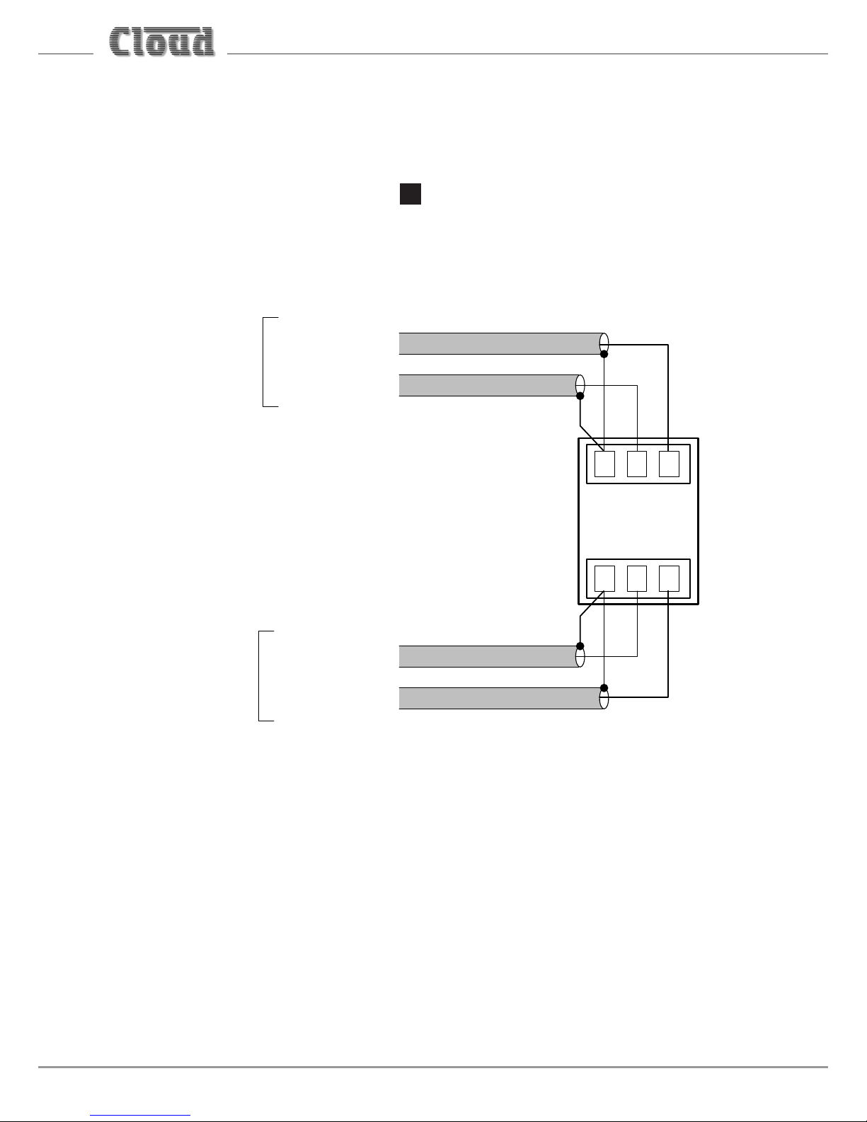
Line inputs
The unit has two stereo line inputs 1. These inputs are suitable for most music
sources such as CD/DVD players, satellite receivers and computer line outputs.
Both inputs are unbalanced and use 3-pin 3.5 mm-pitch screw terminal connectors.
The connectors should be wired as follows:
0V L R
LINE 1
LEFT CHANNEL
RIGHT CHANNEL
LINE 2
LEFT CHANNEL
RIGHT CHANNEL
AUDIO
SOURCE 1
AUDIO
SOURCE 2
Unless a Cloud remote control plate or module such as the RSL-6 or LM-2 is in use,
the two line inputs are summed together internally, though Line input 1 can be
configured to have priority over Line input 2, see “Line 1 Priority” on page 19.
Page 19

MA40E Installation and User Guide v1.0
19
Sensitivity & Gain Control
Each of the stereo line inputs has an input impedance of 10 kohms and a preset
type gain control on the rear panel adjacent to the input sockets 2. The gain
controls have a range of 20 dB allowing the input sensitivity to be varied from
-12 dBu to +8 dBu (0 dBu = 0.775 V
rms
). The gain controls should be set so that the
input sources in use do not distort, and the front panel level controls 1 and 2
have a useful range.
Music Level and EQ control
The front panel LINE 1 and LINE 2 controls 1 and 2 should be adjusted during
installation to set the volume of the audio sources. The line inputs are summed
post the level controls; equalisation can be applied using the front panel LF and HF
controls 3 and 4, which can apply a cut or boost of up to 10 dB at 50 Hz and
10 kHz respectively. If it is not intended to make use of the enhanced EQ adjustments
available on the browser pages, simply adjust the EQ controls by ear to suit the
audio programme material being used, the speaker characteristics and the room
acoustics. If the programme material includes speech, the EQ should be adjusted
for best intelligibility.
If the line input levels are set too high, the amplifier’s dynamic protection will
activate to prevent clipping and the front panel PEAK LED 7 will illuminate to
indicate this.
Line 1 Priority
When both line inputs are in use, one audio source can be given automatic priority
over the other by connecting it to Line 1 input and setting rear panel SETTINGS
DIP switch 1 (LINE 1 PRI) to ON. This is a useful facility when a Digital Sound Store,
emergency announcement system or similar source forms part of the audio system.
When Line 1 Priority is enabled, the amplifier will route the input signal at Line 2
normally until a signal is detected at Line 1’s input. When this happens, it switches
its music source automatically to Line 1. Once the signal at Line 1 stops (e.g., when
an announcement finishes), Line 2’s source will smoothly restore to its former level
over approx. 3 seconds.
Page 20

MA40E Installation and User Guide v1.0
20
Output
The power amplifier stage is fully protected against DC offset, over-current, overand under-voltage and is also thermally protected: activation of the protection
circuitry shuts the power amplifier stage down. All protection conditions except
DC offset will automatically self-clear when the fault is removed. In the case of DC
offset detection, the amplifier will require power-cycling, which is indicated by the
POWER LED flashing red.
A switch-on delay function mutes the output during power-up and power-down to
protect loudspeakers.
The MA40E will deliver its rated power of 20 W per channel into a 4 ohm load when
powered by the external PSU supplied with the amplifier. The maximum output
power will be reduced with lower supply voltages (please refer to MA40E datasheet
for power de-rating curve).
When connecting multiple loudspeakers (generally 8 ohms) to either channel,
series and parallel wiring should be employed to produce a total load impedance of
not less than 4 ohms.
The amplifier outputs are available at the 4-pin 5 mm-pitch screw terminal
connector SPEAKER OUTPUT on the rear panel 4.
Connecting to 100/70/25 V line systems
The MA40E may be used to drive 100/70/25 V line loudspeaker systems if external
transformers are employed.
When driving 100/70/25 V line loudspeaker systems there is a risk of transformer
core saturation at high levels and low frequencies, which can produce distortion.
To prevent this, the MA40E’s output stage is provided with a variable frequency
high-pass filter. The filter is enabled and adjusted via the internal web pages: see
“Speaker EQ tab” on page 38 for details. We recommend that the filter is always
enabled when the amplifier is used with 100/75/25 V line systems.
Page 21

MA40E Installation and User Guide v1.0
21
Facility Port
The MA40E amplifier is provided with a FACILITY PORT in the form of a rear panel
RJ45 connector 3. The primary use of the Facility Port is for the connection of an
LM-2 or BT-1 remote active module, but it may also be used to connect RL and
RSL Series remote control plates, or as a general-purpose mono auxiliary balanced
input (see “Using the Facility Port as an auxiliary input” on page 26 for more
information on this application).
The active modules operate from DC power supplied by the MA40E. The current
consumed by each module is minimal and in the vast majority of installations there
will be no power supply issues.
IMPORTANT: In order for the remote control functions on an LM-2 module or an
RL/RSL Series plate to operate, SETTINGS DIP switch 2 (LOCAL/REMOTE) must
be set to REM. The front panel LINE 1 and LINE 2 controls remain operational and
we recommend that they are set to maximum to ensure full range of level control
is available from the remote module or plate. LINE 1/LINE 2 selection will also be
available from an LM-2. However, it should be noted that the front panel level
controls and the level and/or source selection controls on a remote control module
or plate connected at the Facility Port will be disabled if the corresponding web
browser controls are enabled; see “Input Routing tab” on page 35 for full details.
DIP switch 2 should be left set to LOC when a BT-1 is connected to the Facility Port.
The pinout of the Facility Port connector is given in the table on the following page.
Page 22

MA40E Installation and User Guide v1.0
22
Facility Port connector pinout:
PIN USE Cat 5 CORE*
1 Audio ‘cold’ phase (-) White + Orange
2 Audio ‘hot’ phase (+) Orange
3 Priority VCA control White + Green
4 + 12 V Blue
5 0 V White + Blue
6 -12 V Green
7 Music level control (0 to 3.3 V) White + Brown
8 Music source select control (0 to 3.3 V) Brown
SCN GND ref for system music controls Connector shell
* Standard wiring for pre-made cables
Page 23

MA40E Installation and User Guide v1.0
23
Connecting an LM-2 or BT-1
MIC LEVEL
1
2
3
4
5
6
MUSIC LEVEL
LINE INPUT
MIC INPUT
LM-2
MIC
PRIORITY
1
4
5
2
3
6
7
9
10
8
0
1
4
5
2
3
6
7
9
10
8
0
1
4
5
2
3
6
7
9
10
8
0
BT-1
PUSH
STATUS
- -
TO PAIR
2s 5s
The LM-2 is an active input module which allows a microphone and a stereo line
input in a remote location to be connected to various Cloud host units, including the
MA40E. The module also includes the functions of a Cloud RSL-6 Remote Control
Plate, which allows remote control of the MA40E’s music level and selection of
Line 1 or Line 2 as the music source.
LM-2
BT-1
Page 24

MA40E Installation and User Guide v1.0
24
The BT-1 is a Bluetooth remote audio input module which enables compatible
portable devices such as laptops, tablets and smartphones to stream audio
wirelessly to the module, and thus into the audio system of the area where the
module is installed.
NOTE: The MA40E is only compatible with the BT-1F variant of the BT-1: do not
attempt to connect variant BT-1E.
The LM-2 or BT-1 should be connected to the MA40E’s FACILITY PORT using
screened Cat 5 cable. (Note that as the cable carries analogue audio, only screened
Cat 5 should be used.) The LM-2 includes controls for local music level and source
selection, the wiring for these functions being catered for on the Facility Port. The
maximum total Cat 5 cable length should not exceed 100 m.
LM-2: The LM-2’s upper PCB is fitted with an RJ45 connector labelled OUTPUT.
Connect this to the FACILITY PORT using screened Cat 5 cable with screened RJ45s
at each end. Follow the colour coding shown in the table on page 22 The metal
screening of the connectors should be bonded to the screen of the cable. Full details
can be found in the LM-2 Installation Guide.
Before the LM-2’s music source and level controls will operate, set SETTINGS
DIP switch 2 to REM. For use with an LM-2, we recommend that the front panel
LINE 1 and LINE 2 controls are set to maximum. Positions 3 to 6 on the LM-2’s
Music Source switch have no function on the MA40E; selecting these positions will
effectively mute both line inputs.
BT-1: The BT-1 has two PCBs “piggy-backed” onto the rear of the faceplate. The
RJ45 output connector (SK1) is located on the upper PCB. This should be connected
to the MA40E’s FACILITY PORT with screened Cat 5 cable and shielded RJ45 plugs.
Full details can be found in the BT-1 Installation Guide.
Page 25

MA40E Installation and User Guide v1.0
25
Connecting an RL or RSL Series remote control plate
The MA40E is also compatible with standard Cloud remote control plates of the
RSL Series (music source select and level), and RL Series (level only). The MA40E
differs from most other Cloud products in that it does not have a dedicated 3-pin
“Remote Control” port: RL and RSL Series plates must instead be connected to the
Facility Port 3. This is most easily accomplished by using screened Cat 5 cable
between the MA40E and the remote control plate, but only connecting the one (or
two) cores concerned with the remote control functions (see page 22), plus the
screen, to the plate.
123
FACILITY PORT (RJ45)
123
RL-1 REMOTE LEVEL CONTROL WIRING
RL-1
Screened Cat 5 cable
456
7
8
WHITE + BROWN
WHITE +
BROWN
SCREEN
SCREEN
IGNORE ALL
OTHER CORES
1 2 3
RSL-6 REMOTE SOURCE & LEVEL CONTROL WIRING
RSL-6
123
FACILITY PORT (RJ45)
Screened Cat 5 cable
4 5 6 7 8
WHITE + BROWN
WHITE + BROWN
SCREEN
SCREEN
IGNORE ALL
OTHER CORES
BROWN
BROWN
Page 26

MA40E Installation and User Guide v1.0
26
Using the Facility Port as an auxiliary input
The Facility Port provides a mono balanced audio input. If a port is not connected
to a remote input module or remote control plate, it may be used as an additional,
balanced line input. The signal applied at the Facility Port is mixed with the other
inputs (LINE 1 and LINE 2), but has no independent level control on the amplifier;
the signal level must be adjusted at the source.
Connect an external balanced source to the Facility Port as shown below:
FACILITY PORT (RJ45)
1
3
2
BALANCED
OUTPUT (e.g., XLR)
hot (+)
hot (+)
cold (-)
cold (-)
Twin-core screened cable
1
2
3
4
5
6
7
8
An unbalanced source may also be connected; the use of balancing transformers is
recommended.
Music Mute Input
External muting of music may be commanded through the MUSIC MUTE connector.
National or Local Authority regulations governing installed audio systems may
require that normal programme material (i.e., music) should be muted in an
emergency, to ensure that any evacuation messages are clearly audible. When
active, it mutes all line inputs (including that at the Facility Port).
The Music Mute input is on a 2-pin 5 mm-pitch screw-terminal connector. It should
be connected to the appropriate alarm output on whichever building management
system registers the alarm (typically the Fire System). The alarm output must be
volt-free; if no such output is available, an intermediate relay or other isolation
device must be installed between the alarm output and the Music Mute input.
Page 27

MA40E Installation and User Guide v1.0
27
The Music Mute input can be set to operate on either normally open (N/O) or
normally closed (N/C) contacts via internal jumper J5 (see page 61). The factory
default setting is N/O, thus requiring a short-circuit to be applied across the two
pins of the connector for muting to occur.
REMOTE MUSIC MUTE TERMINATIONS
1 2
MUSIC MUTE
INPUT
RELAY
NORMALLY OPEN (NO)
CONNECTION
1 2
MUSIC MUTE
INPUT
RELAY
NORMALLY CLOSED (NC)
CONNECTION
Auto Power Down
The MA40E is an extremely energy-efficient amplifier, but can be made even
more so by enabling the Auto Power-Down feature. When active, the signal level
is constantly monitored and if no input signals are measured for 15 minutes the
amplifier enters a “Sleep” mode, minimising power consumption. If a signal is
detected while the channel is in this mode, the amplifier “wakes up” in less than
100 ms.
The MA40E is shipped with the Auto Power Down function disabled. It may be
enabled by removing internal PCB jumper J4. See page 61 for details of jumper
locations.
Page 28

MA40E Installation and User Guide v1.0
28
ETHERNET CONTROL OF THE MA40E
The MA40E has a server function, which makes control pages available in a browser
running on any device on the same network as the amplifier. This permits easy
configuration and real-time control of the MA40E from any convenient device on
the network.
OS and Browser compatibility
The MA40E uses standard TCP/IP and UDP-based networking protocols, and is
therefore broadly compatible with modern desktop and mobile operating systems.
Checking browser compatibility
The Web Browser-based user interface requires HTML5, CSS3, localStorage and
WebSockets support, which are provided as standard in current Web browsers.
If there is any doubt regarding browser compatibility, Cloud recommends the use of
the website html5test.com to check which features your browser supports.
Configuring the network
NOTE: This section of the manual is intended for those with a working understanding
of basic computer network configuration and the terminology involved.
Ethernet connection to the MA40E can be simplified by the use of the Cloud
Ethernet Discovery Tool. This can be downloaded from www.cloud.co.uk; navigate
to Resources and select Downloads in the resource selector. The Discovery
Tool is available in two distinct versions:
• an executable JAR file, which will run on Linux, Windows or Mac systems
within a Java Runtime Environment (available from www.java.com)
• a Windows-specific application, which does not require Java.
Page 29

MA40E Installation and User Guide v1.0
29
Download the most appropriate version for your operating system, and save it in a
convenient location.
During initial setup, the MA40E may be connected directly to a laptop Ethernet
interface, using either a straight or crossover Ethernet cable. In this scenario, both
the laptop and MA40E will configure themselves using Link-local IP addresses and
will be able to communicate without the requirement for DHCP, or further network
infrastructure. Using this temporary connection, the MA40E can be set up and
configured to use either DHCP (the default) or a specific, static IP address suitable
for the target network. If a static IP address is to be used, Subnet Mask and Gateway
must also be set correctly. If Gateway details are unknown, the value 0.0.0.0 can be
used safely.
Alternatively, the MA40E may be connected to a spare port of an Ethernet switch
on an existing network, and set up from any device on the same network. In this
scenario, DHCP is the expected method for IP address allocation during the initial
setup procedure. If the network does not support DHCP, then the direct-connection
method described above should be used to assign the correct static IP address first.
Run the Discovery Tool; this will open the window shown below, which should
contain an entry with the host name MA40E.
NOTE: If a warning message appears referencing Windows Firewall, it can be safely
ignored by closing the message box.
Page 30

MA40E Installation and User Guide v1.0
30
Double-click on the MA40E entry. This should open your default browser and make
the MA40E login page visible.
The first page to be displayed on initial connection will be the PIN entry page; enter
the Installer PIN (the factory default is 12341) to authorise access. Click Login and
the Zone 1 page2 will be displayed, with the Input Routing and Output tabs
open as shown on the following page.
1. It is recommended that the factory default PIN is changed to something less obvious when installation
is complete.
2. The web browser pages have been designed as a generic software application covering multiple Cloud
products: although the MA40E only supports a single Zone, the Zone numbering system is retained.
Page 31

MA40E Installation and User Guide v1.0
31
NOTE: For security, the server has a time-out of one minute; if no browser activity
occurs within this time, it reverts to the login page and the PIN will need to
be re-entered.
Page 32

MA40E Installation and User Guide v1.0
32
Click the menu icon at the right-hand end of the Installer banner
and now select Cong, followed by Network. This will open the Network
Conguration page:
We recommend that the MA40E should either be set with a static IP address
(i.e., with DHCP disabled), or uses a fixed DHCP allocated-address on your routing
hardware. It will then have a fixed IP address on the network for other devices to
browse to. Ensure that a suitable IP address is reserved on the network to which you
intend to connect the device. If the MA40E changes IP address, users or third-party
control applications may not be able to locate it. (Installers may need to consult
the client’s IT Manager for guidance.)
Note that when DHCP is enabled, values in the IP Address, Subnet Mask
and Gateway fields are set automatically and the fields are no longer modifiable.
Page 33

MA40E Installation and User Guide v1.0
33
MA40E browser control
Once the network has been set up as described above, most of the MA40E’s
functions may be controlled remotely from a web browser running on a computer
or other device anywhere on the same network.
Click the menu icon on the title bar at any time to see the main drop-down
menu.
Zone 1 page
Control and configuration of the MA40E’s audio functions is done via the
Zone 1 page. The page is divided into five tabs: Input Routing, Room EQ,
Front Panel EQ, Speaker EQ and Output. You can open or close any of the
tabs by clicking on the tab name bar.
The MA40E functions under browser control are summarised in the enhanced block
diagram on the following page.
Page 34

MA40E Installation and User Guide v1.0
34
Page 35

MA40E Installation and User Guide v1.0
35
Input Routing tab
• Enabled – each of the three slider controls on the Input Routing tab
has an Enabled switch. With the switch set to Yes, the associated slider is
operative; in the No position, the slider is greyed out. In the case of the two
Line Level sliders, setting Enabled to Yes disables the front panel level
controls LINE 1 1 and LINE 2 2.
• Input Source – when enabled, click the < and > buttons to select the
line inputs. Mixed is the default option: both Line 1 and Line 2 are enabled,
and the two stereo inputs summed together internally. The other options are
Line 1 (Line 2 is disabled), Line 2 (Line 1 is disabled) and Off (both Line
1 and Line 2 are disabled). An audio source connected via the Facility Port
remains active in all settings, and will be mixed with Line 1 and/or Line 2.
• Line 1 Level – when enabled, click the + and – buttons to adjust
the level of the Line 1 input signal. Note that the buttons do not autorepeat when the mouse button is held down. The scaling is in dBs, with 0
representing maximum; the horizontal bar indicates the setting of the level
control. When greyed out by setting Enabled to No, the bar continues to
reflect to position of the front panel LINE 1 control 1.
• Line 2 Level – operates in an identical manner for Line Input 2.
Page 36

MA40E Installation and User Guide v1.0
36
Room EQ tab
The Room EQ section provides a flexible equaliser allowing the installer to optimise
the amplifier to the room acoustics and programme material. The EQ has “basic”
and “advanced” modes.
The EQ section is placed in circuit and the controls made visible by setting the
Enabled switch to Yes. With Advanced mode set to Off, the basic controls
are displayed:
In Basic mode, simple treble and bass shelving filters are provided. The controls have
a range of +/-12 dB at frequencies of 10 kHz and 50 Hz respectively.
Setting Advanced mode to Yes makes additional controls visible:
Page 37

MA40E Installation and User Guide v1.0
37
The Room EQ is now reconfigured as a seven band parametric equaliser, with peak/
shelf switching on the highest and lowest bands. The Band buttons assign the
rotary controls to each frequency band in turn: all bands have the same frequency
range of 20 Hz to 20 kHz, adjusted by the Freq (Hz) control. However the
seven default centre frequencies are 60 Hz, 250 Hz, 1 kHz, 2 kHz, 4 kHz, 8 kHz and
16 kHz, which will be suitable for most installations. The Gain (dB) control has
a range of +/-12 dB.
For Bands 2 to 6, a Q control replaces the Low Shelf (Band 1) or High Shelf
(Band 7) switch:
The Q control adjusts the bandwidth of the peaking filter over a range of 0.3 (broad)
to 3 (narrow).
Bands 1 and 7 have Low Shelf and High Shelf switches respectively, which
convert the filters constituting these bands between peaking and shelving types.
The default is with the shelving switch On; in this mode the Q control is removed as
it has no function in a shelving filter.
Page 38

MA40E Installation and User Guide v1.0
38
Front Panel EQ tab
The on-screen rotary controls on this tab are not active: they are mimics of the
physical front panel controls. With the Enabled switch set to Yes (the default
setting), the mimics are visible (though they are always greyed out) and the physical
controls themselves are enabled. Setting Enabled to No disables the controls and
places the EQ section “out of circuit”, resulting in a “flat” EQ response; this will
generally be desirable if the Room EQ software controls are to be used.
Speaker EQ tab
The Speaker EQ tab has controls for a steep high-pass filter intended for
loudspeaker protection, and when enabled, a further five-band parametric equaliser,
which can be used to accurately tailor the amplifier’s frequency response to match
that specified by speaker manufacturers.
The default configuration is for both the protection filter and the EQ to be disabled:
Page 39

MA40E Installation and User Guide v1.0
39
Setting the Protect Enabled switch to No disables the high-pass protection
filter and restores the amplifier’s maximum frequency response. The high-pass
filter is a variable-frequency, fourth-order type (slope 24 dB/oct), and has a
frequency range of 40 Hz to 20 kHz. The default frequency is 65 Hz, which should
be satisfactory for many models of 100/70 V line loudspeaker when the amplifier
is used with an external transformer. The frequency is adjusted with the HP Filter
control; use the + and – buttons to alter the value.
The Speaker EQ section is made active with the EQ Enabled switch. Setting this
switch to Yes makes additional controls visible. The EQ section has “basic and
“advanced” modes, selected with the Advanced mode switch. With the switch
set to No, two additional selector switches are displayed:
In this mode, it is possible to select a specific loudspeaker EQ preset from a set that
has previously been installed. Installation of loudspeaker presets is via a firmware
update.
Click on the < and > buttons of the Manufacturer and Model selectors to
choose the preset required. If the Manufacturer selector displays None, no
presets are available. In this case, the Model selector will display Flat, confirming
that the Speaker EQ section will not affect the amplifier’s frequency response.
Page 40

MA40E Installation and User Guide v1.0
40
If a preset is not available, but the installer has the manufacturer’s recommended
EQ settings for the loudspeaker being used, set the Advanced mode switch to
On. This changes the control set as shown:
A five-band parametric equaliser is now available. The three rotary controls
Freq (Hz), Gain (dB) and Q adjust the frequency band selected by the Band
buttons: use the < and > buttons to adjust the values. Default centre frequencies
are 60 Hz, 250 Hz, 1 kHz, 4 kHz and 16 kHz, but may be set with the Freq (Hz)
control to any frequency between 20 Hz and 20 kHz in each band. The default Q
setting is 0.7 in all five bands, but may be set to any value from 0.3 to 3. The range
of the Gain (dB) control is +/-12 dB.
Use the controls to set the EQ curve according to the manufacturer’s data, which
will usually be in the form of a number of dBs of cut or boost at specific frequencies.
If a Q value is not provided, the default value of 0.7 may be taken as acceptable.
Page 41

MA40E Installation and User Guide v1.0
41
Output tab
The Output tab provides controls for the MA40E’s output stage.
• The Output Level slider is the master level control and affects both Line 1
and Line 2 inputs. Click the + and – buttons to adjust. At the minimum setting
of -90, the amplifier will effectively be off. The Output Level control has
an associated Enabled switch, which must be set to Yes for the slider to
be operative. Note that the Output Level control does affect the level of
a signal applied at the Facility Port, i.e., from an LM-2 or BT-1 remote input
module.
• Mute – set Mute to On to mute the amplifier’s output.
• Mono – the default setting for this switch is No. In this mode, the two
channels remain independent and the amplifier operates in stereo. Setting
Mono to Yes sums the two channels at the input to the power output stage,
and both outputs will carry the same summed mono signal.
• Trim Left and Trim Right – these two rotary controls may be used
as fine output level adjustments for each channel, and have a range of 6 dB.
Their default setting is 0 dB (maximum). Note that these controls affect the
individual amplifier outputs in either setting of the Mono switch.
Note that the Mute, Mono and Trim controls are within the amplifier’s output
stage, and thus affect all inputs, including the Facility Port.
Page 42

MA40E Installation and User Guide v1.0
42
Configuration menu
The Cong Menu has pages concerned with global and network settings, definition
of access privileges for different users and renaming options.
Page 43

MA40E Installation and User Guide v1.0
43
User Security
Expanding the User Security menu item opens the list of Users:
The MA40E security system allows up to five Users - in addition to the Installer unique PIN access to the control pages. Additionally, a Guest User may access the
control pages without a PIN. Clicking on any of User 1 to User 5 opens the User
privileges page for that User, as seen on the following page.
Page 44

MA40E Installation and User Guide v1.0
44
Note that only an Installer may define Users and change their access privileges.
The flexibility of the security system allows a client – if they wish - to give particular
members of staff access only to certain control functions. Level control and/or
source selection may be defined individually for each user.
To define User privileges, click in the PIN field under the Access Control tab,
delete the default hyphens and then enter a PIN for the User. Click Update – a
confirmation message will appear. The switches under the Access Permissions
tab define the control functions that will be available for the User to control.
User Enabled must be set to Yes for the functions displayed below to take
effect. Set Level 1 Control, Level 2 Control, Source Control and
Output Control to Yes or No according to requirements.
Once User privileges have been defined, the User(s) may log on using their own
PINs, and will be presented with page layouts containing only those functions
which their access privileges allow. An example is shown below, where User 2 has
been given access to input source selection and output level but not to input level
adjustment.
Page 45

MA40E Installation and User Guide v1.0
45
This will give User 2 the control page shown below:
Page 46

MA40E Installation and User Guide v1.0
46
Users will see a main menu as below – note that most of the Cong submenu
options are not available.
A User PIN may be changed by the Installer at any time from the User Security
page for the specific User by deleting the current PIN – which will be displayed
in the PIN field, entering a new PIN and clicking Update again. A confirmation
message will be displayed.
Guest User
The security system provides for one additional User – the Guest User.
If User Enabled is active for the Guest User, it is possible to browse to the web
interface pages without a PIN being requested. However, as with any other User,
only those functions that have been assigned by an Installer will be available. The
Guest User has been included to allow casual access to unit functionality without
a PIN logon.
Page 47

MA40E Installation and User Guide v1.0
47
Change Installer PIN
Select Change Installer PIN from the menu to open the Reset your
PIN Page.
This page lets you change the Installer PIN. You will need to confirm the current
PIN in the Enter your current PIN field before proceeding to enter a new
one in both the Add a new PIN and the Conrm your new PIN fields, and
Click the Update button.
If the Installer PIN is forgotten or lost, a factory reset (see “Power-up Mode and
Power-up Defaults” on page 49) will reset it to 1234.
Page 48

MA40E Installation and User Guide v1.0
48
Labelling
The Labelling page allows the Installer to change the names of the line inputs
and the area covered by the amplifier (the default “Zone 1”). Names entered on the
Labelling page will replace the default names on all browser pages where they
appear. This provides a much more intuitive interface for both Installer and Users.
Renaming is simply a matter of selecting the default name in the field(s) and
entering the new name(s). Clicking the Upload button will upload all the labels
simultaneously; the names are loaded into non-volatile memory in the amplifier.
The Refresh button reloads the Labelling page from the MA40E, and thus
may be used to discard any changes that have been made to the labels on-screen
since the last click of the Upload button.
Page 49

MA40E Installation and User Guide v1.0
49
General Settings
Power-up Mode and Power-up Defaults
It will often be desirable for the MA40E’s settings (input selections, levels, etc.),
to be automatically restored to a known state when the unit is re-powered after
being off for a period (intentionally or otherwise). The Power Up Mode function
determines the state the MA40E “wakes up” in when it is powered-up.
The Power-up Mode button selects the active power-up option from the three
available: Factory, Default and Last Used.
With Factory selected, the amplifier will return to its original factory settings
at the next power-up. A list of factory settings can be found in the Appendix. If
Power-up Mode is set to Default, the settings which have been saved in the
Default memory (see below) will be restored. The third option, Last Used, will
restore the amplifier settings to what they were when the unit was last powered
off. This is the factory default option, and will be set at the first power-up after
Factory is selected.
Use the Save Defaults button to store the amplifier’s current state in the
Default memory. This will ensure that when the amplifier is powered off and on
again, it will resume the same state. This is particularly important when a mixture
of hardware control (front panel or remote plates) and browser control is being
used.
Page 50

MA40E Installation and User Guide v1.0
50
The Reset Defaults button may be clicked to restore the Default memory to
the original factory settings. The original settings disable all the browser controls.
The Front Panel EQ controls are enabled. Reset Defaults will be most useful
in resetting the MA40E’s Default memory to a known initial “off” state.
RS232 Baud Rate
The default baud rate for the RS-232 serial port is 9600 baud. Use the Baud Rate
+ and – buttons to select an alternative if necessary. The rates available are 4800,
9600, 19200, 38400, 57600 and 115200 baud. For all baud rates, word structure
uses 8 bits, one stop bit and no parity.
Note that the RS-232 baud rate setting only applies to the RS-232 port, not to
serial commands sent via Ethernet.
Page 51

MA40E Installation and User Guide v1.0
51
Network
Select Network from the menu to open the Network Conguration page.
This page displays the network settings for the MA40E. The current IP Address,
Subnet Mask, Gateway address and Unit Name are confirmed. If DHCP
is set to On, the values in IP Address, Subnet Mask and Gateway are set
automatically and the fields greyed out. If assigning these values (with DHCP set
to Off), ensure that a suitable, reserved static IP address is used. This may require
consultation with the network administrator.
Page 52

MA40E Installation and User Guide v1.0
52
Unit Name – this field has a default value of ‘MA40E’. In an installation where
several MA40Es are installed, it will probably be more helpful if each is given a more
meaningful name, e.g., relating to the use to which amplifier is being put.
Click the Reset button to reset the page to the previous state if any changes have
been made but not uploaded. Click the Upload button to transfer any changes to
the amplifier.
Server Ports: in the vast majority of installations, the network parameters in
this tab will not need adjustment. However, they are likely to become relevant if the
MA40E is connected to an existing IT network. The correct settings for these items
will vary from one installation to another, and we recommend that the network
administrator is consulted as to the appropriate values.
HTTP Port – this is the virtual port that a browser will connect to. The default is universally “80”.
It is sometimes changed for firewalling or “security by obscurity” reasons. If this is the case, the
value has to be specified in the browser URL with a colon, eg., http://cloud.co.uk:9000/ would be
required if the HTTP port was set to 9000.
Bridge Port – this is the TCP/IP port used by the MA40E’s Ethernet to Serial Bridge
functionality. See page 59 for more details.
TCP Parser Port – this is the TCP/IP port used to receive serial control commands via Ethernet
(instead of via the RS-232 port)
UDP Parser Port – this is the port used to receive serial control commands via the UDP layer
of TCP/IP. This is useful for broadcast and multicast control applications.
Multicast Address – this is the address of the multicast group to be used for serial commands
via UDP, if the Multicast switch is set to On.
Page 53

MA40E Installation and User Guide v1.0
53
Save/Restore
Select Save/Restore from the menu to open the Save/Restore Settings
page. This lets you save the current unit settings to a file and also to reload the
settings into the MA40E amplifier. This feature will be particularly useful when
installing a system with several MA40Es, all of which need to be configured similarly.
Under the Save Settings to File tab, click Save to download the current
MA40E settings to the computer or other device being used to access the web
pages. The browser will treat the file in the same manner as all downloadable files,
and will probably present a warning message: an example is shown on the following
page (using Mozilla Firefox running under Windows 7).
Page 54

MA40E Installation and User Guide v1.0
54
The file will always be called settings.ma40e_cong and your device will
save it to the default folder used for downloads.
To load a previously saved settings file into the MA40E, open the Restore
Settings from File tab, and click the ... button. This will open a standard
file window: navigate to the settings file and select it. Click Restore to upload the
settings into the amplifier: a confirmation message will be given when the upload
is complete.
Page 55

MA40E Installation and User Guide v1.0
55
Device Info
Select Device Info from the menu to open the Device Information page.
This is an “Engineering” page which gives details of the versions of the various
firmware elements in the MA40E.
Page 56

MA40E Installation and User Guide v1.0
56
MA40E SERIAL CONTROL
The MA40E is equipped with a bi-directional RS-232 serial interface.
As a receiver, the interface permits external control of almost every MA40E function,
and largely replicates the facilities available through the browser interface. The
MA40E appears as a DCE (Data Communications Equipment) device to controlling
equipment. As the controlling device will probably be configured as a DTE device,
this requires the use of a straight (uncrossed) cable with the Tx (Data Transmit) pins
at the cable ends connected to each other and the Rx pins (Data Receive) similarly
connected to each other.
The full RS-232 protocol is beyond the scope of this manual, but it can be
downloaded from www.cloud.co.uk. This section provides only serial port details
and an abridged serial command list.
Pinout
The rear panel RS232 connector is a 3-pin, 3.5 mm-pitch screw-terminal connector.
The pinout is shown in the table:
PIN LABEL FUNCTION
1 0V Ground
2 Rx Data transmit (to control system)
3 Tx Data receive (from control system)
Note that not all control systems interpret “Tx” and “Rx” the same way, and the
installer should check whether pins 2 and 3 should be “crossed” within the cable.
Port parameters:
PARAMETER VALUE/SETTING
Data type RS-232 serial
Data speed
4800/9600/19200/38400/57600/115200 baud,
software-selectable
Word length 8 bits
Parity None
Stop bits One
Page 57

MA40E Installation and User Guide v1.0
57
The MA40E is additionally able to receive the same serial commands in the form of
TCP/IP data via the ETHERNET INTERFACE connector.
Abridged command set
The commands listed in the table below are some of those most commonly required
when controlling an MA40E from an AV control system. For all other commands,
data requests and responses, please refer to the full RS-232 protocol document.
GENERAL FORMAT
FUNCTION COMMAND (ASCII)
Enable input source selection
<B1.IS,E/>
Disable input source selection
<B1.IS,D/>
Select input source(s) to x (see Example 1)
<B1,Sx/>
Enable Line x level control
<B1.Lx,E/>
Disable Line x level control
<B1.Lx,D/>
Increase Line Input x level by m dB
<B1.Lx.LUm/>
Decrease Line Input x level by n dB
<B1.Lx.DUn/>
Enable output level control
<B1.OL,E/>
Disable output level control
<B1.OL,D/>
Mute output
<B1,M/>
Unmute output
<B1,O/>
Increase Output level by m dB
<B1.LUm/>
Decrease Output level by n dB
<B1.LDn/>
Page 58

MA40E Installation and User Guide v1.0
58
Examples:
1. Input Selection
Following the principle of the web browser pages, most of the audio control
functions need to be enabled for external control before adjustment, if they are not
already enabled. The first of the two serial commands shown below enables input
selection for external control (in case, via the serial port).
EXAMPLE COMMAND (ASCII)
Enable input selection
<B1.IS,E/>
Select input source
<B1,Sx/>
The value of x in the Select input source command is as follows:
x
RESULT
0 Both inputs off
1 Line 1 only
2 Line 2 only
3 Line 1 + Line 2 (mixed)
Page 59

MA40E Installation and User Guide v1.0
59
2. Input Levels
Input levels can either be set to an absolute value (in dBs), or increased/decreased
by a specified number of dBs. Either may be defined in steps of 1 dB.
For absolute levels, the number of dBs corresponds to attenuation rather than gain,
thus 0 dB is maximum level and at -90 dB the zone is muted.
To alter the Zone level by a specified amount, the additional ASCII characters ‘U’
(up) or ‘D’ (down) are added to the string. The values of m and n are the number
of one-dB steps (0 to 90) up or down respectively. A command to increment the
level by a number of dBs greater than the current attenuation will set the level
to maximum. Similarly, a command that would decrement the level below 90 dB
attenuation will mute the Zone output.
EXAMPLE COMMAND (ASCII)
Enable Line 1 level control
<B1.L1,E/>
Set Line 1 level to -12 dB
<B1.L1,L12/>
Reduce level of Input1 by 10 dB
<B1.L1,LD10/>
Increase level of Input 1 by 6 dB
<B1.L1,LU6/>
3. Output level
Output levels are set in the same manner as input levels:
EXAMPLE COMMAND (ASCII)
Enable Output level control
<B1.OL,E/>
Set Output level to -8 dB
<B1,L8/>
Reduce Output level by 3 dB
<B1,LD3/>
Increase Output level by 6 dB
<B1,LU6/>
Page 60

MA40E Installation and User Guide v1.0
60
Using the MA40E as an Ethernet-to-serial bridge
The MA40E may be used as an Ethernet-to-serial bridge. Many AV control systems
now transmit serial data strings in TCP/IP format via an Ethernet interface, rather
than from an RS-232 port. However, some equipment – projectors and other display
devices, for example – only accept serial control via an RS-232 port.
The MA40E is able to receive serial data at the Ethernet port and re-transmit it from
the RS-232 port, and thus act as an Ethernet-to-serial converter or bridge.
RS-232
Serial Port
Ethernet
This function uses the MA40E’s virtual CDI port, whose address has the default
value of 4998. If the controlling device is only able to support remote ports in a
certain address range (i.e., not including 4998), the port address can be changed on
the Network Conguration page of the browser interface (select Cong >
Network).
Page 61

MA40E Installation and User Guide v1.0
61
APPENDIX
PCB layout diagram
To access the internal PCB, disconnect the amplifier from its DC power source and
remove the six 2 mm A/F hex socket-head screws securing the top cover; remove
the cover.
REAR OF UNIT
NOT TO SCALE.
ONLY PRIMARY COMPONENTS SHOWN
J1 J4
DO NOT FIT
A JUMPER
HERE!
J5
J3J2
N/O N/C
Page 62

MA40E Installation and User Guide v1.0
62
Table of internal jumpers and default settings
JUMPER PURPOSE OPTIONS DEFAULT
J1
For factory use only
– do not fit jumpers
here
Present or Absent
AbsentJ2
J3
J4 Auto Power Down Present
J5 Music Mute N/O or N/C N/O
Page 63

MA40E Installation and User Guide v1.0
63
Summary of rear panel DIP switch functions
DIP SWITCH POSITION FUNCTION
SW1
LINE 1
PRIORITY
OFF = PRIORITY OFF
In LOCAL mode (ref SW2), the signals
at LINE 1 and LINE 2 are mixed
together, unless software control
of source selection is enabled. In
REMOTE mode, LINE 1 or LINE 2
is selected by the MUSIC SOURCE
switch on an RSL plate or LM-2
module connected to the Facility
Port, unless software control of
source selection is enabled.
ON = PRIORITY ON
A signal at LINE 1 input has priority
over that at LINE 2: LINE 2 is
automatically muted.
SW2
LOCAL/
REMOTE
OFF = LOCAL
The output level of the selected
source(s) is at maximum volume,
unless software control of output
level is enabled. The two inputs are
mixed together, unless software
control of input source is enabled.
ON = REMOTE
The output level of the selected
source(s) is controlled by the level
control on the remote plate or
module connected at the Facility
Port, unless software control of
output level is enabled. If an RSL
Series plate or LM-2 module is in
use, the Music Source control can
select either LINE 1 or LINE 2, unless
software control of source is enabled.
Note: default settings are in BOLD text.
Page 64

MA40E Installation and User Guide v1.0
64
Table of factory settings
The MA40E will adopt the following settings at the first power-up after Factory
has been selected as the Power-Up Mode on the General Settings web
browser page.
LOCATION CONTROL STATE
Hardware controls
Front panel controls Enabled
Front panel EQ section Active
Room EQ tab Room EQ section Disabled
Speaker EQ tab
Speaker protection (HPF) Disabled
Speaker EQ section Disabled
Output tab
Mode Stereo
Mute Unmuted
Left and Right Trims 0 dB
General Settings Power-up mode Last Used
Page 65

MA40E Installation and User Guide v1.0
65
EMC considerations
The MA40E amplifier fully conforms to the relevant electromagnetic compatibility
(EMC) standards and is technically well behaved. You should experience no problems
interfacing units to other items of equipment and under normal circumstances, no
special precautions need to be taken. If the unit is to be used in close proximity
to potential sources of HF disturbance such as high power communication
transmitters, radar stations and the like, it is suggested that input signal leads be
kept as short as possible. Always use balanced interconnections wherever possible.
We recommend that the MA40E amplifier is not located in close proximity to a
high-power amplifier or similar item of equipment, which may radiate a strong
magnetic field from its power transformer.
Earthing
When several mains powered units are connected together via their signal cables,
there is a risk of one or more earth loops which may cause an audible hum on
the system even with the gain controls set to minimum. The 0 V rail of an MA40E
amplifier is directly coupled to the chassis ground. No interconnection problems
should be encountered, but if there is any hum or other extraneous noise when
source equipment is connected, the situation can generally be remedied by
observing the following guidelines:
1. Always connect sources using balanced connections wherever possible. Note
that, for EMC reasons, the cable screen should be connected at both ends.
2. Use audio isolating transformers (readily available from trade suppliers) at the
inputs if necessary. These will ensure that the amplifier is electrically isolated
from the source equipment.
3. The signal source units should be located as close as possible to the amplifiers
and the metal housing of the various units should not be electrically connected
together through the equipment rack. If this is a problem, rack isolating kits
are available from specialist hardware suppliers. If the problem persists, try
to connect all interconnected units, including power amplifiers to a common
power source to ensure a common ground is provided.
Page 66

MA40E Installation and User Guide v1.0
66
Technical specifications
LINE INPUTS
Frequency Response ±1 dB, 20 Hz to 20 kHz
Distortion <0.05% THD+N @ 1 kHz, full power
Sensitivity 0.2 V (-12 dBu) to 1.95 V (+8 dBu)
Input Gain Control 20 dB range
Input Impedance 10 kohms (unbalanced)
Headroom >10 dB
Noise <-85 dB
Equalisation LF: ±10 dB @ 50 Hz, HF: ±10 dB @ 10 kHz
FACILITY INPUT
Input Impedance 10 kohms (balanced)
Sensitivity 0.775 V (0 dBu)
Noise Gate -55 dBu
EQUALISATION
Front Panel HF: ±10 dB @ 10 kHz; LF: ±10 dB @ 50 Hz
Room EQ (via web pages)
7-band parametric EQ with optional low
and high shelf
Protection EQ
(via web pages)
Fourth-order high-pass filter, 40 Hz – 20 kHz
Speaker EQ
(via web pages)
5-band parametric EQ
OUTPUT
Output Power (1 kHz
continuous sine wave)
2 x 20 W, DC input >15 V
Page 67

MA40E Installation and User Guide v1.0
67
GENERAL
Power Input 12 to 24 V DC. (External 24 V AC adaptor supplied)
Power consumption 47 W
External AC PSU adaptor Universal type, 100 V to 240 V, 47 to 63 Hz
Amplifier Protection
Fixed level signal limiter
Protection against DC, PSU overcurrent, amplifier
overcurrent, over-temperature, supply voltage under/
over-voltage
Resettable internal breaker (no fuses)
Dimensions
(w x h x d)
Net
220 mm x 41 mm x 144.5 mm
8.7” x 1.6” x 5.7”
Shipping
290 mm x 160 mm x 210 mm
11.4” x 6.3” x 8.3”
Weight
Net 750 g
Shipping 1.0 kg
Page 68

www.cloud.co.uk
www.cloudusa.pro
 Loading...