

Page 1
Clearly better sound
Technical Note
TN-012
Connecting an LM-2 to a Line Input on a Z4MK4/Z8MK4
Preamble:
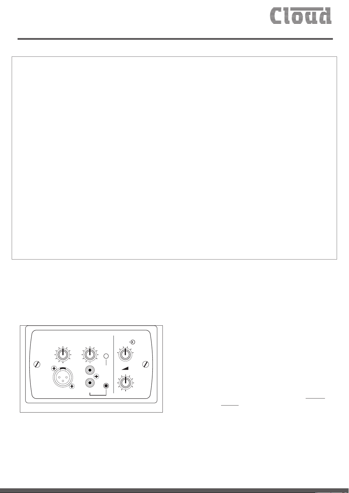
The LM-2* is a remote module for use with Cloud host units tted with an RJ45 Facility Port. It combines
the functions of a remote input connection plate, local audio mixer and a remote control for the host unit’s
background music.
Microphone and stereo line inputs are provided, with individual level controls. The stereo input is summed
to mono, and then mixed with the mic input. The LM-2 is designed to be connected to a Facility Port on
the host unit using screened Cat 5 cable and shielded RJ45 connectors. An audio source connected at the
LM-2 module is then routed into the Zone to whose Facility Port it has been connected (normally the one
where the LM-2 is installed).
It is sometimes useful to be able to make the remote audio source available to every Zone supported by
the host unit, rather than just the one local to the LM-2. To achieve this, the balanced audio signal from the
LM-2 needs to be connected to one of the host unit’s balanced line inputs instead of a Facility Port; it can
then be selected as the music source for each Zone where it is required, from the host unit’s front panel
(or from further LM-2 or RSL-6 Series remote control plates, if they are installed).
This Technical Note describes how to connect an LM-2 module to a balanced line input instead of a Facility Port.
Note that the LM-2 Installation Guide (supplied with each module) should also be referred to while making this
connection.
* The LM-2 is currently available in six style/nish variants: LM-2B, LM-2W, LM-2AB, LM-2AW, LM-2DB and LM-2DW. This Technical Note is
applicable to all variants; the wording “LM-2” is used throughout for brevity.
Applicable products:
Cloud Z4MK4 and Z8MK4 Zone Mixers are tted with
both an RJ45 Facility Port and balanced line inputs
and are thus suitable for the connection described in
this Technical Note.
Parts required:
• 2 x screened RJ45 plugs
• Screened Cat 5 cable of the appropriate length
(host to module location)
• Short length 25 cm (12”) of twin-and-screen
audio cable
• 9-way nylon terminal block (“choc-strip”) suitable
MIC LEVEL
5
4
3
2
1
MIC INPUT
6
0
MUSIC LEVEL
6
7
5
7
4
8
9
10
3
2
1
LINE INPUT
8
9
10
0
MIC
PRIORITY
3
4
2
5
1
3
6
6
5
7
4
8
2
9
10
1
0
LM-2
for 1.5 mm2 (6 A) cable
• Crimp ferrules (white)
• H15 silicone sleeves, 2 mm bore silicone sleeving
• Plastic enclosure to house terminal block with
two cable grommets (recommended but not
essential)
(Note that as the cable carries analogue audio, only screened
Cat 5 cable and shielded RJ45 connectors should be used.)
LM-2 front panel
Page 2
Clearly better sound
Tools required:
RJ45 crimp tool, small wire cutters, wire stripper,
small screwdriver, ferrule crimp tool. A drill will also
be required if an enclosure is being used.
Required Skill Level: Low.
Ability to strip wire neatly, crimp RJ45 connectors,
and use of crimp ferrules.
Procedure - wiring:
The procedure essentially consists of “breaking-out”
three cores of Cat 5 cable and wiring them to one
of the Z4/8MK4’s four balanced line inputs. A terminal
block housed in a plastic enclosure is used to make a
neat and mechanically robust set of connections.
Follow the wiring instructions in the LM-2 Installation
Guide, and install screened Cat 5 cable between the
host unit and the LM-2. Crimp a shielded RJ45 onto
each end of the cable according to the normal wiring
standard, which is included here for completeness:
1
8
8
8
1
1
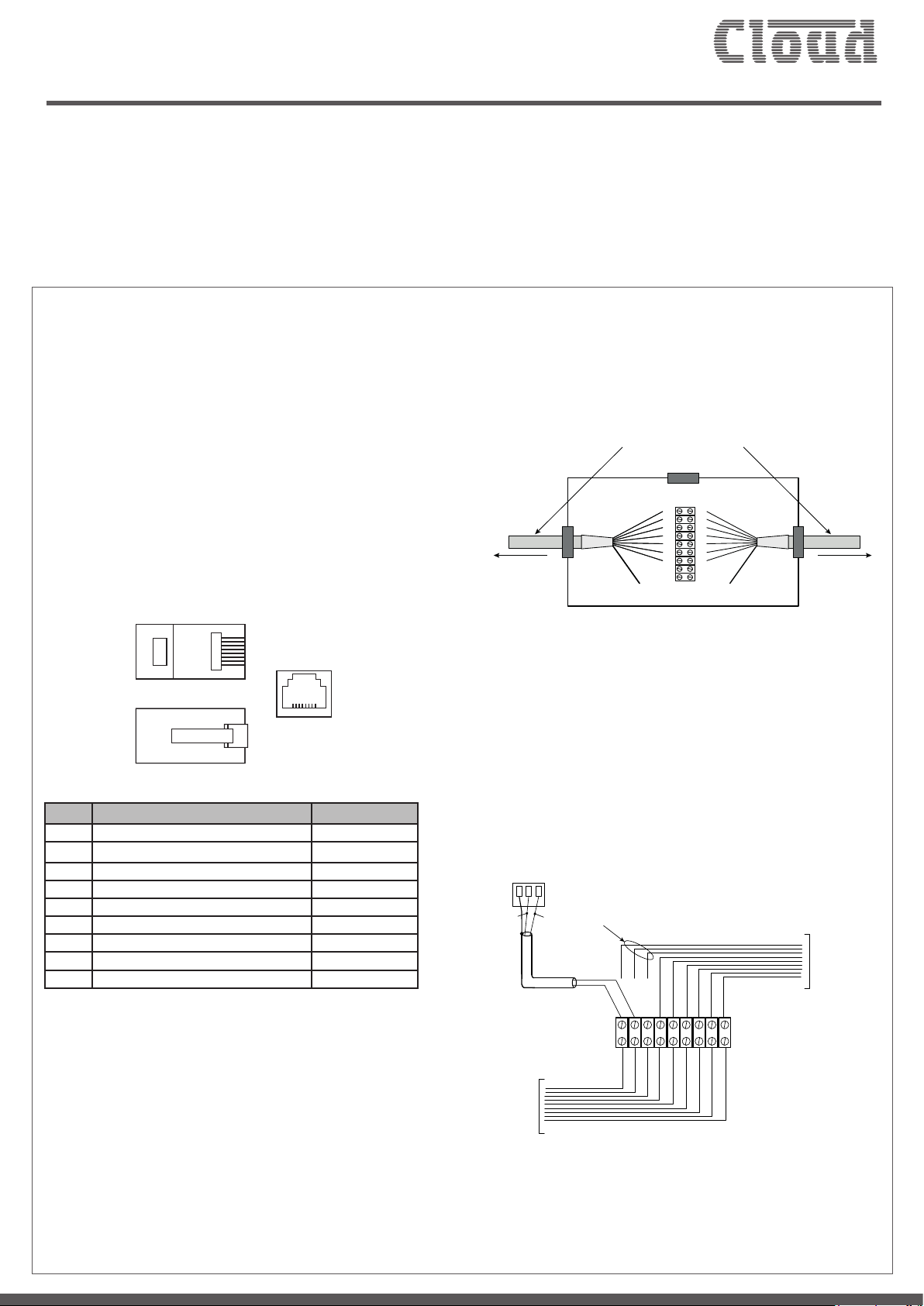
If the terminal block is to be housed in a plastic
container (recommended for neatness), pass
the cables through holes in the enclosure, tting
grommets in the holes rst. (The holes may need to
be drilled.)
Screened Cat 5 cable
FROM LM-2 IN
REMOTE LOCATION
Plastic enclosure with
grommetted entry holes
TO FACILITY PORT
ON HOST UNIT
As Cat 5 cores are invariably solid wires, it is strongly
recommended that crimp ferrules are tted to all
cores to make a mechanically robust connection.
White ferrules should be satisfactory for all the
connections.
PIN USE CAT 5 CORE
1 Audio ‘cold’ phase (-) White + Orange
2 Audio ‘hot’ phase (+) Orange
3 Priority VCA control White + Green
4 +V Blue
5 0 V White + Blue
6 -V Green
7 Music level control (0 to 10 V) White + Brown
8 Music source select control (0 to 10 V) Brown
SCN GND for system music controls Connector shell
At the LM-2 end, plug the RJ45 into the LM-2’s
OUTPUT connector.
Turn the host unit off, plug the RJ45 into the Facility
Port for the Zone in use, then cut the Cat 5 cable
approximately 15 cm (6”) back from the connector.
Strip the jacket back on both ends by about 5 cm
(2”), t H15 sleeves, and fan the cores out, including
the drain wire for the cable screen.
Connect the cores into the terminal block as shown:
Z4/Z8 Balanced Line Input
1 32
Note: Do not connect RJ45
Pins 1, 2 or 3 (Wt/Gn, Or & Wt/Or)
WT/OR
OR
WT/OR
WT/GN
BL
WT/BL
BL
OR
WT/BL
WT/GN
hot (‘+’)
cold (‘-’)
Cat 5 to Facility Port
BN
SCN
WT/BN
GN
9-way Terminal Block
BN
GN
SCN
WT/BN
Twin-and-Screen
Cat 5 from LM-2
hot (‘+’)cold (‘-’)
Audio Cable
Note that the White+Green core (RJ45 pin 3) should
not be connected in this particular application. This
core carries the VCA priority control voltage from
Page 3

Clearly better sound
the LM-2 and use of the PRIORITY button on the
LM-2 will interfere with correct operation in this
case. Disconnecting Pin 3 disables the PRIORITY
switch.
Connect a suitable length of twin-and-screen audio
cable to the terminals carrying the orange pair from
the incoming Cat 5 cable. Do not connect the screen
at the terminal block end. Wire the other end to the
screw-terminal connector for any of Line Inputs 3, 4,
5 and 6 as shown:
PIN CONNECTION
1 Screen
2 Signal ‘-’ (cold)
3 Signal ‘+’ (hot)
Note that Line Inputs 1 and 2 are unbalanced, and use
phono connectors on the Z4MK4 and Z8MK4. Only
make the connections as shown to Line Inputs 3 to 6.
When all connections are made, ret the lid on the
enclosure (if used).
Procedure – host conguration:
In order for the LM-2’s remote control section
(background music source and level controls) to
operate correctly, the host unit must be set for
remote control operation. Please refer to the
Z4/Z8MK4 Installation Guide for full details of how
to do this.
Operation
Once the connections have been made as described,
the audio source(s) connected at the LM-2 will be
available in any Zone by selecting the Line Input to
which the connection has been made as the Music
Source for the Zone.
In all other Zones, the source can be selected either
by a remote control module or plate (e.g., LM-2 or
RSL-6) installed in the Zone, or - if remote controls
are not installed - by the Music Source controls on
the front panel.
In the same way, audio level can be adjusted by either
by a remote control module or plate, or the front
panel Music Level controls, as appropriate.
Note however, that the MIC LEVEL and MUSIC
LEVEL controls on the LM-2 module where the
source is connected now act as “Master” controls
and will alter the levels of the audio source in all
Zones.
In the example diagram shown on the following page,
the global source is connected to an LM-2 in Zone1;
the Cat 5 cable from the LM-2 is “broken out” to Line
In 3 on the Z4
MK4 using the modication described
in this Technical Note. Zones 2 and 3 also have LM-2s
installed, but Zone 4 does not. To route the laptop
audio to all zones, Line In 3 must be selected as the
music source: in Zones 1, 2 and 3 this is done on
the LM-2 modules in each zone, but for Zone 4,
the selection must be made on the front panel of
the Z4MK4. The MUSIC CONTROL switches for
Zones 1, 2 and 3 must be set to REMOTE to enable
their remote control sections, while that for Zone
4 is left at LOCAL, so that the Zone 4 front panel
music controls remain operative.
From the above it will be seen that a practical
method of setting levels might be to rst turn the
Zone Music control on the LM-2 to which the
source is connected to maximum, and then increase
the MUSIC LEVEL until the volume in the Zone
is as high as is ever likely to be required. This will
provide a sensible setting for input gain, and the levels
in other Zones can then be adjusted individually.
In the Zone where the new “global” audio source is
connected to the LM-2, this selection will be made
using the MUSIC LEVEL control on the LM-2 itself,
and the volume in the Zone will be set by the adjacent
MUSIC LEVEL control.*
* This assumes that the LM-2’s remote controls are in use and have thus
been enabled at the host. If they are not, the front panel Music Source
and Music Level controls should be set in a similar way.
Page 4

Clearly better sound
ZONE 2
ZONE 3
MIC INPUT
Select Line in 3 for Zone 2
LINE INPUT
3
2
4
1
0
10
8
9
LM-2
MUSIC LEVEL control is “master” level
for laptop audio throughout system
3
2
4
MIC LEVEL
1
5
6
0
7
10
8
9
3
2
4
MUSIC LEVEL
1
5
6
0
7
10
8
9
PRIORITY
MIC
1
2
5
3
6
4
7
5
6
Adjust the laptop audio level in
Zone 2 here
0
LM-2
Cat 5
MIC INPUT
1
0
LINE INPUT
1
0
PRIORITY
MIC
3
2
4
1
5
6
7
10
8
9
Select Line in 3 for Zone 3
3
2
4
10
8
9
3
2
4
10
8
9
1
6
Cat 5
2
5
5
6
7
5
6
7
3
4
MIC LEVEL
MUSIC LEVEL
Adjust the laptop audio level in
Zone 3 here
MUSIC CONTROL switches are set to
REMOTE for Zones 1, 2 & 3
Source (laptop) connected to LM-2 in Zone 1
Cat 5
ZONE 1
3
2
4
MIC INPUT
LINE INPUT
3
2
1
0
10
9
LM-2
Select Line in 3 for Zone 1
MIC LEVEL
1
5
6
0
7
10
8
9
3
2
4
MUSIC LEVEL
1
5
6
0
7
10
8
9
PRIORITY
MIC
1
4
2
5
3
6
4
7
5
8
6
Adjust the laptop audio level in
Zone 1 here
Cat 5 from LM-2 in Zone 1 is “broken
out” to e.g., Line in 3
Adjust the laptop audio in
Zone 4 here
Select Line In 3 for Zone 4
www.cloud.co.uk www.cloudusa.pro
Issue_1.0
E&OE
 Loading...