

Page 1
FPA-1 Installation Guide v1.1
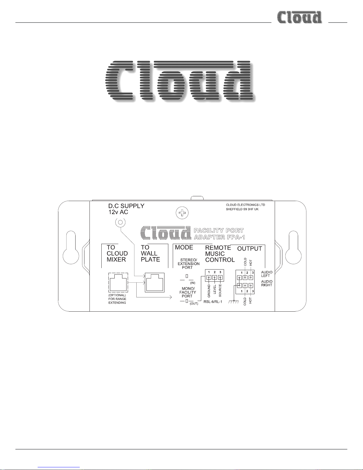
FPA-1
Facility Port Adapter
Installation Guide
Page 2

FPA-1 Installation Guide v1.1
2
Contents
Introduction ................................................................................................................................. 3
Mounting - mechanical............................................................................................................................................... 4
Connections and Controls .......................................................................................................... 5
Block Diagram ............................................................................................................................. 6
Installation – connections ........................................................................................................... 6
Powering the FPA-1 .................................................................................................................................................... 6
Application Examples ................................................................................................................................................. 6
1. Connecting a BT-1E to a CX261 ..................................................................................................................... 8
2. Connecting an LM-2 to an MPA240 ................................................................................................................ 9
3. Connecting an LM-2 to a CX263 .................................................................................................................. 10
4. Connecting an LE-1 to a CX261 ...................................................................................................................11
Technical Specication .............................................................................................................. 12
Page 3
FPA-1 Installation Guide v1.1
3
Introduction
The FPA-1 Facility Port Adapter is an accessory which can be used with almost any Cloud host product – ampliers, zone
mixers, zone mixing ampliers, etc. Its primary purpose is to allow a remote input module tted with an RJ45 connector - such
as the LM-2 and BT-1 - to be used with the host. Without an FPA-1, these remote modules are only directly compatible with
Cloud host units tted with an RJ45 Facility Port, such as the Z4/Z8MK4 and 46-120 ranges.
With an FPA-1, audio sources connected at the remote input module are routed to a line input on the host device, greatly
increasing the exibility of the installation. The FPA-1 supports both mono and stereo operation, and can be used with either
unbalanced or balanced line inputs. The remote control functions of the LM-2 input module are also catered for, allowing remote
volume control of many Cloud mixers and mixer-ampliers.
The FPA-1 is also compatible with LE-1, BE-1 and ME-1 remote input modules: these are normally used with the DCM-1 range
of Digital Control Mixers, but may be interfaced via an FPA-1 to a line input on any host unit, in stereo or mono as appropriate.
A typical application example would be to use the FPA-1 to connect a BT-1E Bluetooth wireless audio module to a CX261
Zone Mixer in a tness centre. This would allow customers to route audio wirelessly from their own smartphones or portable
MP3 players into the audio system, in stereo. The CX261 has stereo unbalanced inputs but no Facility Port; the BT-1E uses Cat 5
cable tted with RJ45 connectors, so interfacing one to a CX261 would normally be problematical. The FPA-1 makes connection
simple: the BT-1E audio source is routed to a CX261 line input.
A secondary use for the FPA-1 is to provide local DC power for a remote input module when unusually long cable lengths
require it. Recommended maximum cable lengths for connecting accessories to host units are detailed in Technical Note
TN-009 which can be found under “Cable Connector List” on the Resources page of the Cloud website. If these cable lengths
are exceeded, or if other technical problems in a particular installation suggest that a separate PSU should be employed, the
FPA-1 acts as a convenient power injection point to supply local DC power to the input module.
IMPORTANT:
The FPA-1 is an extremely versatile interface and may also be used to connect Cloud remote input modules to non-Cloud
ampliers or mixers. However it must be emphasised that the FPA-1 has been developed for use with Cloud products exclusively,
and its performance has only been evaluated using Cloud products. Thus while it is likely that the FPA-1 will operate satisfactorily
when used with some non-Cloud products, no guarantee can be given of correct operation and Cloud Electronics Ltd. accepts
no responsibility for the consequences of any such use.
Page 4
FPA-1 Installation Guide v1.1
4
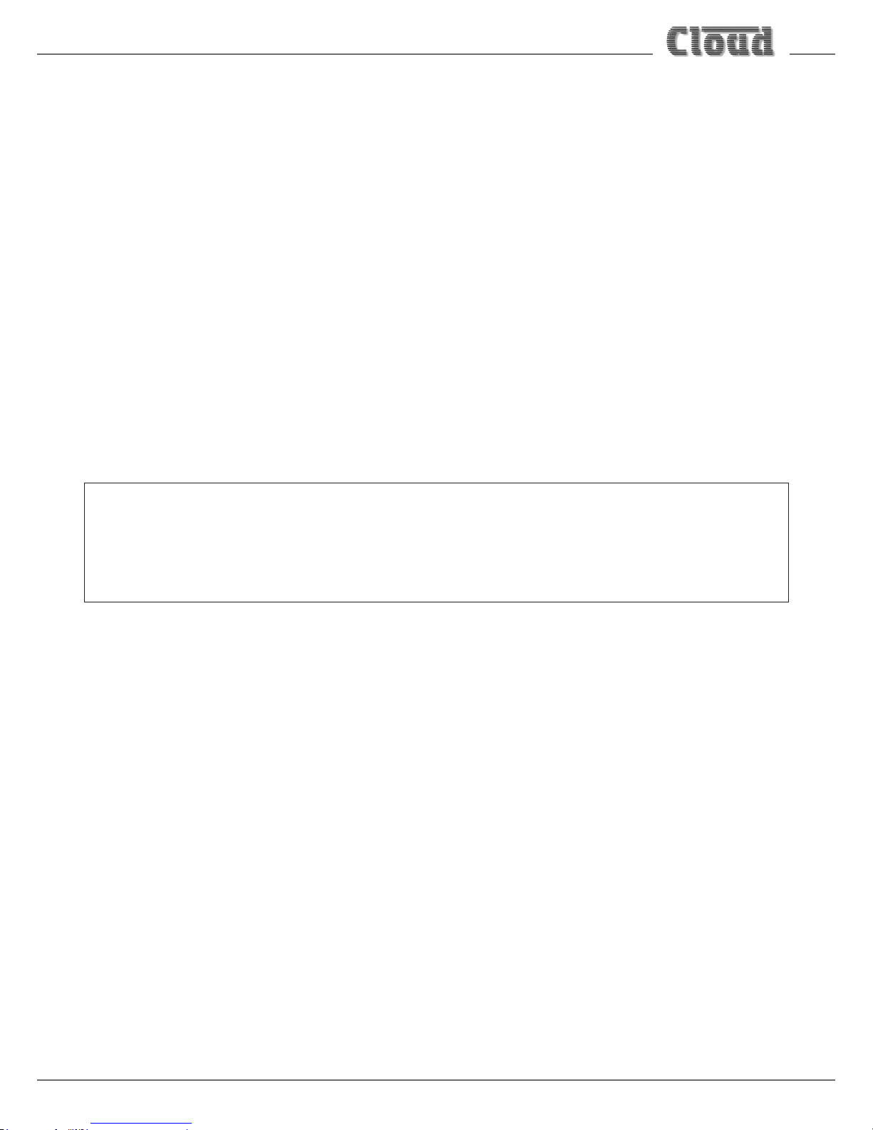
Mounting - mechanical
The FPA-1 is a small steel unit with two “keyhole” slots for mounting. It can be easily xed with wood screws or nuts and bolts
to any convenient surface, in a wall or ceiling void or within a rack or other equipment housing. Power consumption is negligible
and there are no ventilation considerations.
51.60 mm32.90 mm
116.00 mm
R3.75 mm
R2.10 mm
86.60 mm
25.80 mm
16.12mm
Page 5
FPA-1 Installation Guide v1.1
5
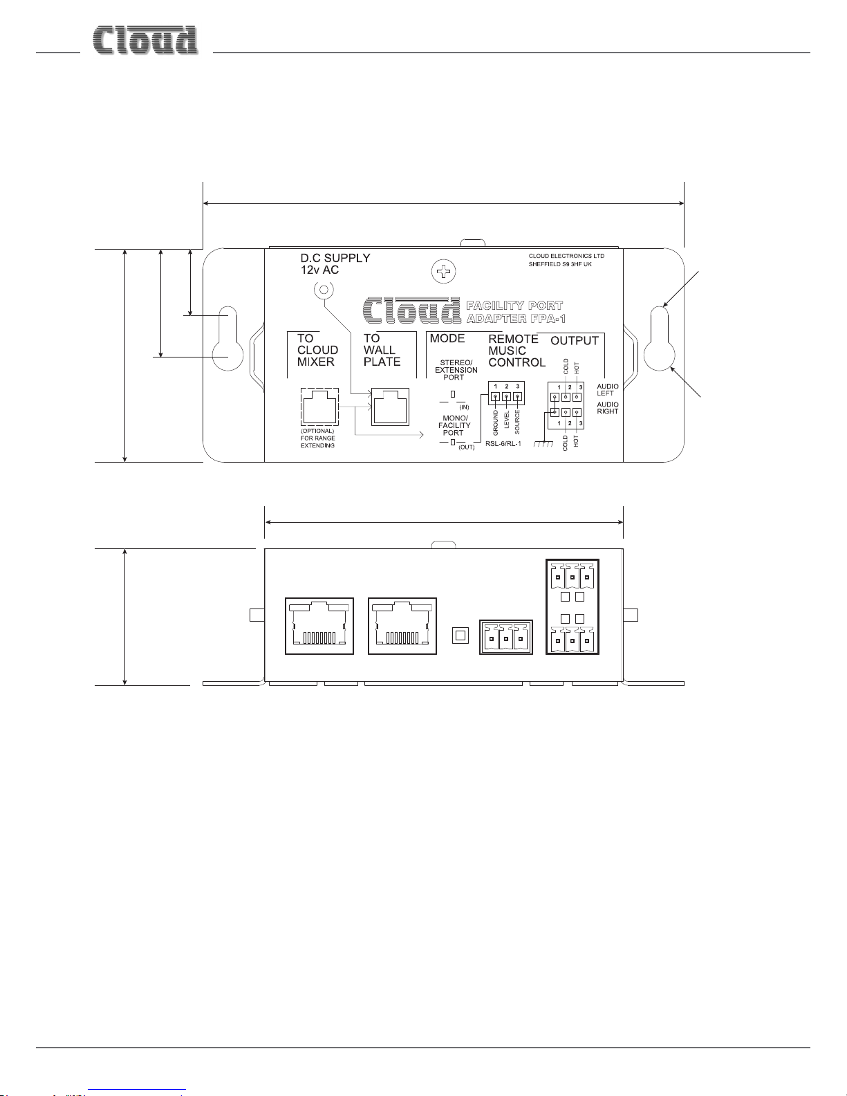
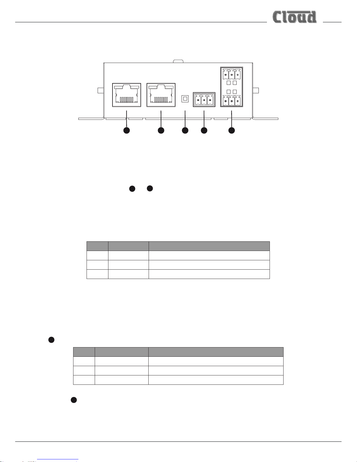
Connections and Controls
12 34 5
1. TO WALL PLATE – connect this RJ45 socket to the remote input module (LM-2, BT-1, LE-1, BE-1 or ME-1) using
screened Cat 5 cable and shielded RJ45 connectors.
2. TO CLOUD MIXER – a connection to this RJ45 socket is optional. If using the FPA-1 as a breakout box to provide local
DC power to a remote input module, this connector can be used to connect to the host’s Facility Port or Extension Port
with screened Cat 5 cable in the normal way.
NOTE: Because both RJ45 connectors 1 and 2 carry analogue audio, only screened Cat 5 and shielded RJ45 connectors
should be used.
3. OUTPUT – two 3-pin, 3.5 mm-pitch screw terminal connectors. Note there are separate connectors for AUDIO LEFT
and AUDIO RIGHT, and each output is electronically balanced. For mono operation, connect either output to a line input
on the host unit; for stereo operation connect both outputs. (Note that many Cloud host units are equipped with stereo
line inputs which are summed internally to mono).
The pinout of each connector is as follows:
PIN SIGNAL NOTES
1 Screen
2 Audio ‘-‘ (cold) Do not use when connecting to an unbalanced input
3 Audio ‘+’ (hot)
4. MODE – a recessed press button switch: set to MONO/FACILITY PORT (button out) to congure the outputs as
mono and to STEREO/EXTENSION PORT (button in) to congure them as stereo.
5. REMOTE MUSIC CONTROL – a 3-pin, 3.5 mm-pitch screw terminal connector for connecting to the host
unit’s remote music control port. (Note that this port is identied in various ways on different Cloud products:
MUSIC CONTROL, RSL-6, etc.)
6. This connector carries the control voltages from the remote level and source controls on the input module connected at
1
e.g., an LM-2. The pinout of the connector is as follows:
PIN FUNCTION NOTES
1 Ground
2 Remote level control
3 Remote source select Do not connect if host unit does not support remote source selection
Setting switch 4 to STEREO disables this connector.
Note: switches (and in many cases, internal jumpers) will need to be set in the host unit in order for remote music controls
to operate.
Page 6

FPA-1 Installation Guide v1.1
6
Block Diagram
RJ45
TO WALL
PLATE
RESETTABLE
FUSE
+/-V
+
+
1,2
AUDIO
RIGHT
BALANCED
OUTPUTS
MODE
SWITCH
MONO
STEREO
+
+
AUDIO
LEFT
CLOUD MIXER PRODUCT
WITH FACILITY PORT
OR EXTENSION PORT
Cat 5 CABLE
> 100M
POWER IN
AC/DC
DC-DC
STEP
DOWN
+/- 15.5 V
REMOTE
MUSIC
CONTROL
MIXER
POWER
+/-12 to15 V
4,5,6
7,8
‘OR’
+/-15.5 V
CLOUD REMOTE
INPUT MODULE
BT-1F, BT-1E, LM-2
BE-1, ME-1, LE-1
RJ45 TO
CLOUD
MIXER
(OPTIONAL FOR RANGE EXTENDING)
Installation – connections
Powering the FPA-1
The FPA-1 will operate from a power supply of 12 V AC or 12 to 24 V DC. A 12 V AC “plugtop” type PSU is supplied with each
adapter. Connect this to the coaxial socket on the rear of the housing.
Application Examples:
The FPA-1 is a highly versatile interface and can be used in a variety of ways for different purposes. Its primary purpose is to
allow remote input modules with only RJ45 connectivity to be used with Cloud host units that are not provided with either
RJ45 Facility Ports or RJ45 Extension Ports. This includes most Cloud products of older design, such as the CX261, CX263,
CX163, MPA, CX and VTX Series ampliers (all current production).
The various methods of connecting the FPA-1 are described below by way of four examples. Use the example that most closely
follows the combination of Cloud items being installed.
In all cases, the remote input module should be connected to the TO WALL PLATE RJ45 socket on the FPA-1 using screened
Cat 5 cable and shielded RJ45 plugs.
IMPORTANT: Because the cables carry low-level audio, only screened Cat 5 should be used, the foil screen of the cable being
bonded to the metal screening can of the plugs. If a remote input module is being installed in very close proximity to the host
unit, it may be possible to use ready-made screened Cat 5 “patch” cables of short length. In all other situations, shielded RJ45
plugs should be crimped onto the installed screened Cat 5 cable using the pinout shown on the following page.
Page 7

FPA-1 Installation Guide v1.1
7
PIN USE (MONO MODE) USE (STEREO MODE) Cat 5 CORE
1 Audio ‘cold’ phase (-) Left audio channel ‘cold’ phase (-) White + Orange
2 Audio ‘hot’ phase (+) Left audio channel ‘hot’ phase (+) Orange
3 Priority VCA control Model sense White + Green
4 +V
supply
+V
supply
Blue
5 0 V 0 V White + Blue
6 -V
supply
-V
supply
Green
7 Music level control voltage Right audio channel ‘hot’ phase (+) White + Brown
8 Music source select control voltage Right audio channel ‘cold’ phase (-) Brown
SCN Screen for system music controls Screen Connector shell
Page 8

FPA-1 Installation Guide v1.1
8
1. Connecting a BT-1E to a CX261
A BT-1 wireless audio input module allows a user to use their Bluetooth-enabled smartphone or MP3 player to be the audio
source for the system to which the BT-1 is connected. The CX261 is a stereo, single zone mixer with six line inputs. An FPA-1
allows a BT-1E module to be interfaced to one of the CX261’s line inputs. Note that as a BT-1E is stereo-capable, the audio
source retains its stereo status through the entire system; the BT-1F variant does not have this capability.
BT-1
PUSH
STATUS
- -
TO PAIR
2s 5s
RJ45
BT-1E
FPA-1
CX261
RJ45
TO WALL
PLATE
Connect L and R to any
unused stereo line input
Set MODE switch to
STEREO
AUDIO
LEFT
AUDIO RIGHT
LR
Screened Cat 5
LINE INPUTS
The audio connection between the FPA-1 and the CX261 line input is most easily achieved with a pre-made twin phono-phono
cable, with the connectors at one end cut off. This can then be connected to the left and right audio outputs of the FPA-1, using
the mating connectors provided.
Note that the inputs to the CX261 are unbalanced while the FPA-1 outputs are balanced. Wire pins 1 (screen) and 3 (hot) only
– do not connect pin 2 (cold).
1
3
+
+
2
SCSCN
FPA-1 Balanced output:
pin 1 ground
pin 2 cold
pin 3 hot
When using single-core cable,
don’t connect ‘cold’ at the
FPA-1
Unbalanced input (e.g. phono)
Page 9

FPA-1 Installation Guide v1.1
9
2. Connecting an LM-2 to an MPA240
The LM-2 is a remote input module which provides mic and line inputs plus remote control of music level and source selection.
The MPA240 is a single zone mixer-amplier for use with either low-impedance or 70/100 V-line systems. An LM-2 can be
interfaced to an MPA240 using an FPA-1 to provide a remote audio input point: audio sources connected here will become
available to the mixer-amplier via a line input, and can be selected with the front panel source selection switch. The LM-2 will
also allow remote control of audio volume.
RJ45
LM-2 (UK Version Shown)
FPA-1
MPA240
RJ45
TO WALL
PLATE
Twin-and-screen cable
Connect to any line input.
Unbalanced connection
Set MODE switch to
MONO
In MONO mode, either
output may be used.
AUDIO
LEFT
AUDIO
RIGHT
Screened Cat 5
MIC LEVEL
1
2
3
4
5
6
MUSIC LEVEL
LINE INPUT
MIC INPUT
LM-2
MIC
PRIORITY
1
4
5
2
3
6
7
9
10
8
0
1
4
5
2
3
6
7
9
10
8
0
1
4
5
2
3
6
7
9
10
8
0
REMOTE MUSIC
CONTROL
The MPA240 has unbalanced inputs, so a phono cable with one end cut off may be used to connect the audio outputs of the
FPA-1 to the amplier. As in Example 1, wire pins 1 (screen) and 3 (hot) only – do not connect pin 2 (cold).
A second connection is required to implement the remote level control function of the LM-2. (The LM-2’s remote source
selection control is unused in this application.) In the case of the MPA240, twin-and-screen cable should be used for the
connection. Ensure that all three connections are made pin-for-pin. Note that the remote control ports on the MPA240 are
marked REMOTE MUSIC CONTROL.
If connecting to a host unit other than an MPA240 mixer-amplier, please consult the specic Installation and User Guide for
details of how to connect to and enable the remote control port, as there are certain differences between Cloud models.
Page 10

FPA-1 Installation Guide v1.1
10
3. Connecting an LM-2 to a CX263
The LM-2 is a remote input module which provides mic and line inputs and remote control of music level and source selection.
The CX263 is a three zone mixer amplier with six line inputs; Zone 1 may be stereo, while Zones 2 and 3 are always mono.
An LM-2 can be interfaced to a CX263 using an FPA-1 to provide a remote audio input point: audio sources connected here
will become available as one of the six amplier sources. The LM-2 will also allow remote control of audio volume and selection
of the audio source.
For Zones 2 & 3, the CX263 sums stereo audio sources internally to mono, while retaining full two-channel operation for Zone
1. Thus the FPA-1 can be set to operate in either mono or stereo mode, depending on the circumstances of the installation.
However, as in Example 2, selection of stereo mode will disable the remote control functions, so this example illustrates the
FPA-1 installation in mono mode. Zone 1 on the CX263 may be recongured for mono operation by internal jumper: depending
how the zones are congured, it may be preferable to connect the mono audio output of the FPA-1 to both the L and R sockets
of the chosen line input. Please consult the CX263 Installation and User Guide for further details.
RJ45
FPA-1
CX263
RJ45
TO WALL
PLATE
Set MODE switch to
MONO
Twin-and-sceen cable
In MONO mode,
either output
may be used
Connect to any unused
line input – either L or R
(but see note regarding
operation of Zone 1)
AUDIO
LEFT
AUDIO
RIGHT
REMOTE MUSIC
CONTROL
Screened Cat 5
LINE INPUTS
Z1, Z2, Z3
REMOTE
LM-2 (UK Version Shown)
MIC LEVEL
1
2
3
4
5
6
MUSIC LEVEL
LINE INPUT
MIC INPUT
LM-2
MIC
PRIORITY
1
4
5
2
3
6
7
9
10
8
0
1
4
5
2
3
6
7
9
10
8
0
1
4
5
2
3
6
7
9
10
8
0
As in Example 1, the audio connection to the host unit is most easily made by cutting off the connector(s) from one end of a
pre-made phono-phono cable. Wire pins 1 (screen) and 3 (hot) only at the FPA-1 end.
A second connection is required to implement the remote control functions of the LM-2. Use twin-and-screen cable for this,
observe the pinout in the REMOTE MUSIC CONTROL table at page 5, and ensure that all connections are made
pin-for-pin. The CX263 has a separate remote control port for each zone: these are marked Z1 REMOTE, Z2 REMOTE and
Z3 REMOTE. In common with most Cloud units supporting remote control, the remote control port will need to be enabled;
in the case of the CX263, this is via a rear panel push-button switch.
If connecting to a host unit other than an CX263, please consult the specic Installation and User Guide for details of how to
connect to and enable the remote control port, as there are certain differences between Cloud models.
Page 11

FPA-1 Installation Guide v1.1
11
4. Connecting an LE-1 to a CX261
The LE-1 is a simple remote input module providing a stereo line input on both phono sockets and a 3.5 mm jack socket. A level
trim control and a Peak LED are included. The CX261 (see also Example 1) is a stereo, single zone mixer with six line inputs.
An FPA-1 will allow a stereo music source to be routed to one of the CX261’s line inputs, retaining its stereo status through
the entire system.
This achieves essentially the same result as Example 1, but allows for a wired connection of the audio source rather than a
wireless one. ME-1 (dual microphone inputs) and BE-1 (two XLR balanced line inputs) modules may be connected in exactly
the same way.
RJ45
LE-1
FPA-1
CX261
RJ45
TO WALL
PLATE
Connect L and R to any
unused stereo line input
Set MODE switch to
STEREO
AUDIO
LEFT
AUDIO RIGHT
LR
Screened Cat 5
LINE INPUTS
The audio connection between the FPA-1 and the CX261 line input is most easily achieved with a pre-made twin phono-phono
cable, with the connectors at one end cut off. This can then be connected to the left and right audio outputs of the FPA-1, using
the mating connectors provided.
Note that the inputs to the CX261 are unbalanced while the FPA-1 outputs are balanced. Wire pins 1 (screen) and 3 (hot) only
– do not connect pin 2 (cold).
Connecting multiple LM-2s
Two or more LE-1s may be installed by employing the LINK connector on the lower rear PCB. The primary purpose of this
feature is so that music sources may be connected into the audio system at different locations. BE-1 modules may also be
chained and intermixed with LE-1s. Note it is not possible to mix ME-1 modules with LE-1s and/or BE-1s.
Page 12

FPA-1 Installation Guide v1.1
12
Technical Specication
ELECTRICAL
Frequency response +/- 0.5dB 20 Hz – 20 kHz
Distortion < 0.01%
Noise <-90 dB
Power Input 12V AC (adaptor supplied) or 12-24V DC
PHYSICAL
Dimensions 116 mm x 33 mm x 54 mm
Shipping Dimensions 200 mm x 140 mm x 80 mm
Weight (discounting PSU) 184 g
Shipping Weight 545 g
Dimensions 116 mm x 33 mm x 54 mm
Page 13

FPA-1 Installation Guide v1.1
13
Page 14

FPA-1 Installation Guide v1.1
14
Page 15

FPA-1 Installation Guide v1.1
15
Page 16

www.cloud.co.uk www.cloudusa.pro
 Loading...