

Page 1
CXL-80T
70/100 V Transformer
Installation Instructions
Important Safety Notes
It should be recognised that 100 V-line or 70 V-line speaker systems have the
potential to deliver an electric shock. Install the CXL-80T only in accordance
with these instructions.
In all cases, the external wiring and associated speakers will need to comply
with local electrical regulations for AC voltages up to 100 Vrms (141 Vpeak).
Do not expose the transformer to rain or moisture.
The transformer module must be installed in a safe manner.
Cloud Electronics Ltd. accept no responsibility for hazardous installations.
CXL-80T Installation Instructions v1.0
1
Page 2
INTRODUCTION
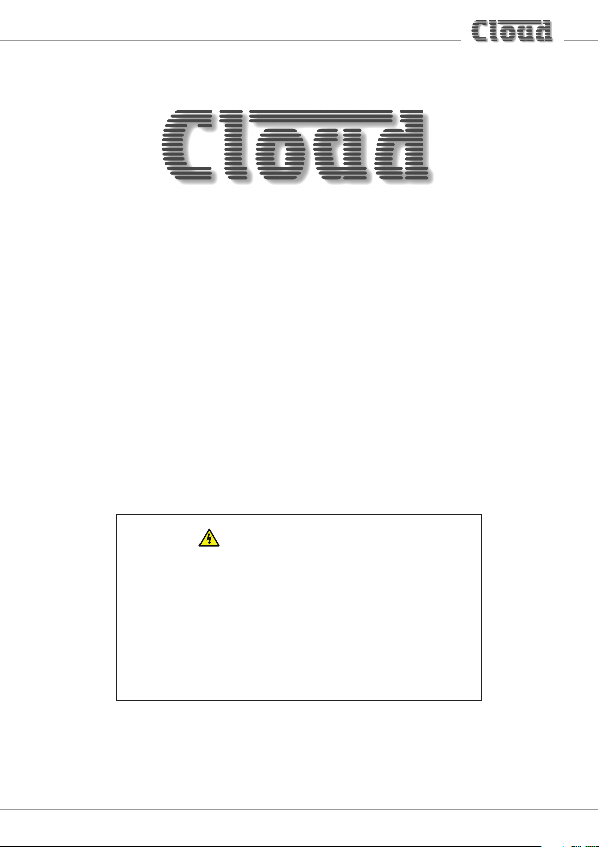
Speaker Outputs
The CXL-80T is an optional transformer for the 46-80 Multi-Zone Mixer Amplifier, to permit the Mixer Amplifier to directly drive
100 V-line or 70 V-line loudspeaker systems. The transformer is rated at 80 W output, and is mounted internally. Up to four
CXL-80Ts (one per output channel) may be fitted to a 46-80. The outputs are available on the 8-pin 5 mm-pitch screw-terminal
SPEAKER OUTPUTS connector on the host unit’s rear panel.
MUTE - N/O OR N/C
PAGING MODE
DIGITAL PAGE MIC
CDPM IN
R
GAIN
L
+10-10
dB
FACILITY PORT MUSIC MUTE
LEVEL
+10-10
dB
[ ZONE 1 ]
UTILITY/LOOP OUTPUT AUX OUT
MIC
MUSIC
100
100
123
CONNECT TO RELAY
ISOLATED CONTACTS
REMOTE MUSIC CONTROL
ZONE 1
EACH 3 PIN CONNECTOR IS INTENDED FOR USE WITH RL-6/RL-1
SERIES REMOTE WALL PLATES
REFER TO USER GUIDE FOR FULL DETAILS
ZONE 1
123
123
-+
ZONE 2
46-80 Rear Panel
NOTE: unlike some other Cloud multi-channel amplifiers, the 46-80 uses a single output connector for both low impedance and
70/100 V-line operation. Thus it is NOT possible for any channel of a 46-80 to drive both low impedance speakers and
70/100 V-line systems simultaneously. The check boxes below the connector should be used to indicate the standard each output
is set for.
ZONE 2
123
SPEAKER OUTPUTS
Z1
-+
-+
70/100V 70/100V 70/100V
70/100V
4 OHM
4 OHM
ZONE 3
123
Z2
Z3
Z4
-+
-+
4 OHM
ZONE 4
123
4 OHM
Z4 SOURCE
Z4 LEVEL
Z3 SOURCE
Z3 LEVEL
Z2 SOURCE
Z2 LEVEL
Z1 SOURCE
LOC
LOCREM
Z1 LEVEL
RS232
123ON45678 123ON45678
REM
0V Rx Tx
SW2: CONTROLSW3: UTIL/PRI/APD
LOC
LOCREM
LOC
LOCREM
LOC
LOCREM
REM
REM
REM
15M30M
OFF ON
OFFON
OFFON
APD ON
APD TIMING
LINE 6 PRIORITY Z1
LINE 6 PRIORITY ALL
UNUSED
UTILITY SOURCE A
UTILITY SOURCE B
0
01
0
UTILITY SOURCE C
1
1
MAX: 150W
POWER 47-63Hz
85-243V AC
CAUTION:
REPLACE WITH SAME
TYPE T5AH 250V FUSE
ATTENTION:
UTILIZER UN FUSIBLE
DE RECHARGE DE MEME
TYPE DE T5AH 250V.
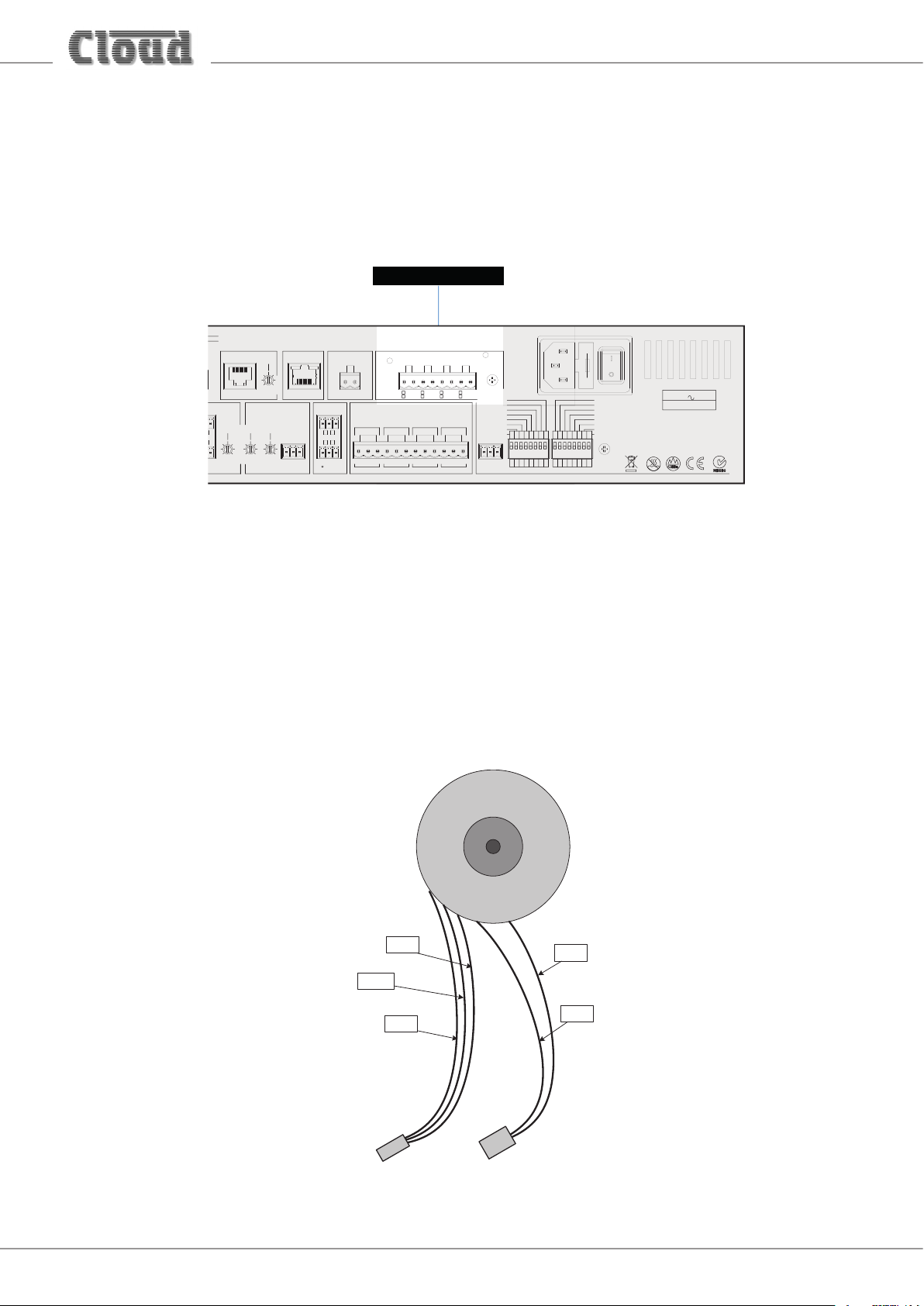
FITTING THE CXL-80T TRANSFORMER
The CXL-80T transformer is a toroidal type, and is supplied pre-terminated with 2-pin and 3-pin connectors as shown:
MAUVE
SECONDARY
WINDING
CONNECTOR
(female)
WHITE
BLUE
CONNECTOR
PRIMARY
WINDING
(female)
RED
BLACK
CXL-80T Installation Instructions v1.0
2
Page 3

Red
White
Purple
-
(0V)
+
100 V
To 70/100 V-line
70 V
Black
Pri. Sec.
CXL-80T
Blue
COM
speaker system
From amplifier
output (Lo-Z)
Each transformer is also supplied with an M4 x 45 Posi-head bolt.
To convert one channel of a 46-80 to 70/100 V-line operation, proceed as follows:
1. Disconnect the 46-80 from the mains.
2. Remove the top cover (8 screws) and orient the unit with the rear panel towards you.
3. Mount the CXL-80T transformer on the right-hand side of the 46-80 chassis, using one of the holes in the side of the chassis
and the M4 bolt supplied with the transformer. The centre of the toroid has a captive M4 nut, so the bolt head should be on
the outside of the chassis. If fitting fewer than four CXL-80Ts, any of the fixing positions may be used. Orient the transformers
so that the flying leads face the rear of the chassis.
4. For the zone being converted to 70/100 V-line operation, unplug both ends of the relevant blue/white twisted pair which
connects the power amplifier modules to the 3-pin headers on the PCB immediately behind the SPEAKER OUTPUT
connector.There are four of these (one per zone): CON30 (Zone 1), CON31 (Zone 2), CON32 (Zone 3) and CON33 (Zone 4) see diagram on the following page.
CXL-80T Installation Instructions v1.0
3
Page 4

CON34 CON35 CON36 CON37
CON30 CON31 CON32 CON33
5. Identify the transformer’s primary winding – this is the red/black flying lead fitted with a 2-pin connector. Plug this into
the relevant power module output connector. Note that each module has two channels, that nearer the front of the chassis
powers Zones 1 and 2, the other Zones 3 and 4. Refer to the diagram on page 5.
6. If configuring the zone output for 100 V-line operation, plug the transformer’s secondary winding – the other flying lead
(blue/mauve/white) - into the 3-pin header behind the SPEAKER OUTPUT connector vacated in Step 4. (This will be the one
closer to the rear panel.)
7. If configuring the zone output for 70 V-line operation, plug the transformer’s other flying lead (blue/mauve/white) into the
alternative 3-pin header behind the SPEAKER OUTPUT connector (this will be the one further away from the rear panel). The
headers are CON34 (Zone 1), CON35 (Zone 2), CON36 (Zone 3) and CON37 (Zone 4).
8. For each zone being converted to 70/100 V-line operation, enable the channel’s 65 Hz hi-pass filter by moving the appropriate
jumper from OFF to ON: these are J3 (Zone 1), J4 (Zone 2), J5 (Zone 3) and J6 (Zone 4). This is important, as low frequency
signals at high level can saturate the transformer cores, causing unpleasant distortion and possibly activating the amplifier’s
limiter circuitry. See the following diagram for location of PCB jumpers.
CXL-80T Installation Instructions v1.0
4
Page 5

9. If converting further Zone outputs to 70/100 V-line operation, repeat Steps 3 to 8 for each output.
10. Replace the cover, using the original screws.
11. Mark the checkboxes below the SPEAKER OUTPUTS connector with a felt-tip pen to indicate the mode of operation for each
channel.
Power module output
headers – Z1 & Z2
TO FRONT PANEL PCB
J3
J4
J6
J5
J7
J8
J9
Power module output
headers – Z3 & Z4
POWER MODULE – Z1 & Z2
Z2 Z1
Z4 Z3
POWER MODULE – Z3 & Z4
J10
J11
UPPER PCB
J1
J2
46-80 MAIN PCB - REAR VIEW
SIMPLIFIED VIEW - ONLY PRIMARY
COMPONENTS SHOWN
J12
J13
Z1 Z2 Z3 Z4
MAIN PCB
Output connectors for
70 V-line operation
Output connectors for Lo-Z or
100 V-line operation
CXL-80T Installation Instructions v1.0
5
Page 6

www.cloud.co.uk
www.cloudusa.pro
 Loading...