

Page 1

CV AMPLIFIER
User Guide
Cloud Electronics Limited
140 Staniforth Road, Sheffield, S9 3HF England
Tel +44 (0)114 244 7051
Fax +44 (0)114 242 5462
e-mail
info@cloud.co.uk
web site http://www.cloud.co.uk
Page 2

CV AMPLIFIER USER GUIDE 1
Installation
InstallationInstallation
Installation
CV500, 800 & 1000
CV500, 800 & 1000CV500, 800 & 1000
CV500, 800 & 1000
These amplifiers occupy three units of rack space (i.e. 5.25"/133mm). All three amplifiers feature front
entry forced air cooling which enables any number of amplifiers to be racked without the need for
special ventilation provided that a free flow of air is available at the rear of the rack hou sing.
All the CV range of a mpl if i er s ar e d es igned for conti nu ou s ope r ation at high power l evels and will tolerate
a good deal of abuse. Output short circuits or mis-matched loads , can be tolerated without harm.
Input Connections
Input ConnectionsInput Connections
Input Connections
Inputs to all the amplifiers are con nec ted via XLR-3-31 type connectors. The inpu t circ ui t is e lectr onical ly
balanced and where possible, the balanced mode is preferable. If the input is used in the unbalanced
mode, pin 3 must be linked to pin (Ov). The input is then connected to pin 1 (ground) and pin 2 (hot).
When used in the balanced mode, pin 1 is ground, pin 2 is in-phase, pin 3 in non phase.
Input impedance is 20K ohms balanced, 10K ohms unbalanced.
Provided pin 3 is grounded in the unbalanced mode, the input sensitivity is 0dBu (775mV) for both
balanced and unbalanced modes.
Output Connections
Output ConnectionsOutput Connections
Output Connections
The output from all the CV amplifiers is connected via an XLR-3-32 type connector or binding posts. The
minimum recommended load is 4 ohms. The two output channels must never be connected in parallel.
XLR connections are pin 1 = 0v, pin 2 = phase (hot).
Mode of Operation
Mode of OperationMode of Operation
Mode of Operation
All amplifiers have a 3 position mode switch on the rear panel, adjacent to the Ch annel B input socket.
Stereo
StereoStereo
Stereo
In the centre position marked "Stereo" the amplifier operates as two independent channels for typical
stereo operation.
Mono
MonoMono
Mono
With the switch in the "Mon o" po si ti on the channel A input is int ern ally connected to driv e bo th ch an ne ls
of the amplifier. The front level controls remain in operation as normal and the limiters also work normally
on each channel. When the " Mono" mode is in use, the appropriate LED on the front panel illuminates,
and channel B input is disabled.
Bridge
BridgeBridge
Bridge
With the switch in the "Bridge" position the load should be connected between the two "Hot" output
terminals (XLR pin 2 or Red binding posts). The amplifier then operates as a single channel unit with a
minimum load impedance of 8 Ω. Channel A input socket, limiter and level control are operative, with
channel B input circuits disabled. The "Bridge" LED on the front panel illuminates when the mode switch
is in this position.
Important.
Important.Important.
Important. In the bridge mode, the full output of the combined channels is available at the output
terminals and care m us t be taken to ens u re th at th e l ou dsp eakers are ca pable of h an dli ng t h e ava il able
power.
Page 3

2 CV AMPLIFIER USER GUIDE
Mains Connections
Mains ConnectionsMains Connections
Mains Connections
The amplifie r i s p rov i ded wit h 3 pin Euro conn e cto r m ou nt e d on the rear pa nel , a su it able mains lea d wi th
plug is supplied.
CAUTION: This amplifier must be
CAUTION: This amplifier must be CAUTION: This amplifier must be
CAUTION: This amplifier must be earthed.
earthed.earthed.
earthed.
All the CV amplifiers can be suppl ied to oper ate o n 220 v or 2 40 v A.C. m ains supplies . Refer to the se rvice
manual if the supply vo ltage requires changing.
Level Control
Level ControlLevel Control
Level Control
Independent level controls are provided for channels A & B. These would normally opera te in the fully
clockwise position. The limiter op erate s i n the post level circuitry and is n ot aff ect e d by th e po siti o n of the
level control.
Limiter
LimiterLimiter
Limiter
The limiter circuit uses a studi o quality VCA with compr eh ens iv e side chain circui try. The fast attack time
of 0.5ms ensures accurate control of transients, and the release time is program related: Fleeting
overloads recover quickly whilst sustained limiting has a longer release characteristic. A release hold off
circuit prevent s "c ontrol voltage indu ce d distortion" at low frequ e n cie s. Al l th i s adds u p to a st udio qual ity
limiter, with very musical performance. When the limiter is correctly set up it is not possible to drive the
amplifier into clipping, this protects the loudspeakers from overdrive, and is par ticularly effective for
tweeter protection.
The limiter is factory set at 0.5dB below the onset of clipping with a 4 Ω load. All amplifiers are supplied
with the limiter circuit switched on.
To avoi d th e risk of un auth oris ed adju stm ent th e li mite r on-off s witc hes ar e mo unte d on the power ampli fier
printed circuit boards. Each channel can be switched independently. A small LED on the rear panel
illuminates when the limiter is switched into operation.
Limiter switching
Limiter switchingLimiter switching
Limiter switching:::: To switch the limiter in or out of circuit, first remove the top cover. Locate the switch
marked "SW2" which is on the upper main PCB, on the right side when viewed from the front. The switch
on/off position is detailed on the PCB. A small screwdriver is required to operate the switch on channel
B. Insert the screwdriver through the hole adjacent to "SW2" on channel A to operate an identical switch
on channel B. Visual indication of limiter in/out status is provided by small LED's on the rear panel.
Limiter Threshold
Limiter ThresholdLimiter Threshold
Limiter Threshold:::: This control adjusts the po int at which limiting commences. It is factory set to limit the
output to 0.5dB below the threshold of clipping when operating into a 4 ohm load. If the amplifier is
operating with a load impedance greater than 4 ohms, a small increase in output can be gained by
adjusting the threshold control. This should only be carried out by experienced technicians, using
electronic test equipment. Refer to the service information for further details.
Page 4

CV AMPLIFIER USER GUIDE 3
LED Indicators
LED IndicatorsLED Indicators
LED Indicators
Protect:
Protect:Protect:
Protect: The Red "PROTECT" LED indicates the operation of various protection circuits built into the
CV range of amplifiers. It also illuminates when the 5 second switch-on delay is operating.
Signal:
Signal:Signal:
Signal: The Green "SIGNAL" LED illuminates to indicate normal operation of the am plifier and the pr ese nce
of an output signal above 20dBm (7.75v).
Peak:
Peak:Peak:
Peak: The R ed "P E AK " L E D i ll u m i na te s ap pr o xi mat e ly 1 dB be f or e t h e ampl ifier reaches clippi n g p oint. The
reference circuits are load dependant and operate accurately for 4 to 16 ohm loads.
This LED also indicates that the threshold of limiting has been reached when the limiter is
in circuit.
NOTE: If the "PEAK" LED's are on, no damage is being caused to the amplifier, it merely
indicates waveform clipping, or limiting, if the limiter is operating.
Mono:
Mono:Mono:
Mono: The Yellow "MONO" LED indicates that the "Mono" mode is in operation.
Bridge:
Bridge:Bridge:
Bridge:The Yellow "BRIDGE" LED illuminates when the amplifier is switched into the "Bridge" mode.
Protection
ProtectionProtection
Protection
The Cloud CV multiple protection circuits include output open and short circuit protection, thermal sensing
operating independently on each channel, D .C l o ad pr ote c ti on, 5 second switch-on mute, s ophisticated
Over-current protection.
The CV800 and 1000 also have anti-surge power switch-on units fitted. (Soft-Start).
This product conforms to the following European Standards
This product conforms to the following European StandardsThis product conforms to the following European Standards
This product conforms to the following European Standards
BS EN 50081-1
BS EN 50081-1BS EN 50081-1
BS EN 50081-1 : 1992
: 1992: 1992
: 1992
BS EN 50082-1
BS EN 50082-1BS EN 50082-1
BS EN 50082-1 : 1992
: 1992: 1992
: 1992
BS EN 60065
BS EN 60065BS EN 60065
BS EN 60065 : 1994
: 1994: 1994
: 1994
SAFETY CONSIDERATIONS
SAFETY CONSIDERATIONSSAFETY CONSIDERATIONS
SAFETY CONSIDERATIONS
CAUTION
CAUTION CAUTION
CAUTION - MAINS FUSE
- MAINS FUSE- MAINS FUSE
- MAINS FUSE
TO REDUCE THE RISK OF FIRE R E P LACE THE MAINS FUSE ONLY WITH THE SAME TYPE, WHICH MUST BE A CLASS 3, 240 VOLT, TIME DELAY TYPE, RATED
TO REDUCE THE RISK OF FIRE R E P LACE THE MAINS FUSE ONLY WITH THE SAME TYPE, WHICH MUST BE A CLASS 3, 240 VOLT, TIME DELAY TYPE, RATEDTO REDUCE THE RISK OF FIRE R E P LACE THE MAINS FUSE ONLY WITH THE SAME TYPE, WHICH MUST BE A CLASS 3, 240 VOLT, TIME DELAY TYPE, RATED
TO REDUCE THE RISK OF FIRE R E P LACE THE MAINS FUSE ONLY WITH THE SAME TYPE, WHICH MUST BE A CLASS 3, 240 VOLT, TIME DELAY TYPE, RATED
AT 5A-CV500, 6.3A-CV800, 8A-CV1000 WHERE THE MAINS INPUT VOLTAGE IS SET TO 230 Volts ±5%AC.
AT 5A-CV500, 6.3A-CV800, 8A-CV1000 WHERE THE MAINS INPUT VOLTAGE IS SET TO 230 Volts ±5%AC.AT 5A-CV500, 6.3A-CV800, 8A-CV1000 WHERE THE MAINS INPUT VOLTAGE IS SET TO 230 Volts ±5%AC.
AT 5A-CV500, 6.3A-CV800, 8A-CV1000 WHERE THE MAINS INPUT VOLTAGE IS SET TO 230 Volts ±5%AC.
FOR A MAINS VOLTA GE OF 115 Volts ±5%AC. THE FUSE SHOULD BE RATED AT 8A-CV500, 10A- CV800,
FOR A MAINS VOLTA GE OF 115 Volts ±5%AC. THE FUSE SHOULD BE RATED AT 8A-CV500, 10A- CV800, FOR A MAINS VOLTA GE OF 115 Volts ±5%AC. THE FUSE SHOULD BE RATED AT 8A-CV500, 10A- CV800,
FOR A MAINS VOLTA GE OF 115 Volts ±5%AC. THE FUSE SHOULD BE RATED AT 8A-CV500, 10A- CV800, 15A-CV1000
15A-CV100015A-CV1000
15A-CV1000
THE FUSE BODY SIZE IS 20mm x 5mm.
THE FUSE BODY SIZE IS 20mm x 5mm. THE FUSE BODY SIZE IS 20mm x 5mm.
THE FUSE BODY SIZE IS 20mm x 5mm.
CAUTION
CAUTION CAUTION
CAUTION - SERVICING
- SERVICING- SERVICING
- SERVICING
THIS UNIT CONTAINS NO USER SERVICEABLE PARTS. REFER ALL SERVICING TO QUALIFIED SERVICE PERSONNEL. DO NOT PERFORM ANY SERVICING
THIS UNIT CONTAINS NO USER SERVICEABLE PARTS. REFER ALL SERVICING TO QUALIFIED SERVICE PERSONNEL. DO NOT PERFORM ANY SERVICINGTHIS UNIT CONTAINS NO USER SERVICEABLE PARTS. REFER ALL SERVICING TO QUALIFIED SERVICE PERSONNEL. DO NOT PERFORM ANY SERVICING
THIS UNIT CONTAINS NO USER SERVICEABLE PARTS. REFER ALL SERVICING TO QUALIFIED SERVICE PERSONNEL. DO NOT PERFORM ANY SERVICING
UNLESS YOU ARE QUALI FI E D TO DO SO.
UNLESS YOU ARE QUALI FI E D TO DO SO.UNLESS YOU ARE QUALI FI E D TO DO SO.
UNLESS YOU ARE QUALI FI E D TO DO SO.
WARNING
WARNINGWARNING
WARNING
TO REDUCE THE RISK OF FIRE OR EL ECTRIC SHOCK DO NOT EXPOSE THIS EQUIPMENT TO RAIN OR MOISTURE.
TO REDUCE THE RISK OF FIRE OR EL ECTRIC SHOCK DO NOT EXPOSE THIS EQUIPMENT TO RAIN OR MOISTURE.TO REDUCE THE RISK OF FIRE OR EL ECTRIC SHOCK DO NOT EXPOSE THIS EQUIPMENT TO RAIN OR MOISTURE.
TO REDUCE THE RISK OF FIRE OR EL ECTRIC SHOCK DO NOT EXPOSE THIS EQUIPMENT TO RAIN OR MOISTURE.
Page 5
4 CV AMPLIFIER USER GUIDE
Specifications
SpecificationsSpecifications
Specifications
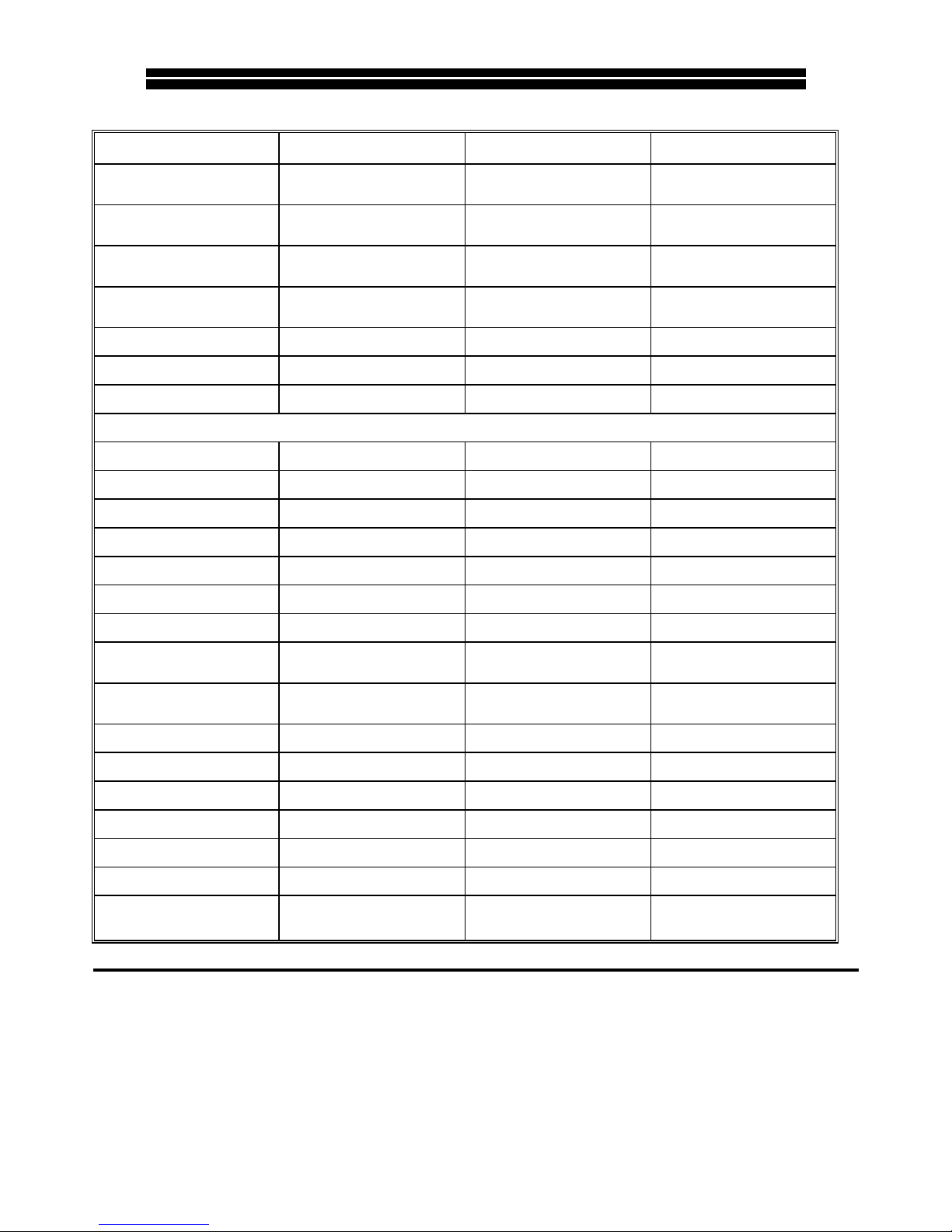
GENERAL SPECIFICATION
GENERAL SPECIFICATIONGENERAL SPECIFICATION
GENERAL SPECIFICATION CV500
CV500CV500
CV500 CV800
CV800CV800
CV800 CV1000
CV1000CV1000
CV1000
INPUT
INPUTINPUT
INPUT Electronically balanced via XLR 3-31
per channel
Electronically balanced via XLR 3-31
per channel
Electronically balanced via XLR 3-31
per channel
OUTPUT CONNECTORS
OUTPUT CONNECTORSOUTPUT CONNECTORS
OUTPUT CONNECTORS 1 XLR 3-32 & 2 heavy duty binding
posts per channel
1 XLR 3-32 & 2 heavy duty binding
posts per channel
1 XLR 3-32 & 2 heavy duty binding
posts per channel
PROTECTION
PROTECTIONPROTECTION
PROTECTION VI Limiting,DC Offset,Thermal
Shutdown with Auto reset
VI Limiting,DC Offset,Thermal
Shutdown with Auto reset, Soft start.
VI Limiting,DC Offset,Thermal
Shutdown with Auto reset, Soft start.
LED INDICATORS
LED INDICATORSLED INDICATORS
LED INDICATORS 'Peak Output', Signal Present' 'Limiter
On', 'Protection Operating'
'Peak Output', Signal Present' 'Limiter
On', 'Protection Operating'
'Peak Output', Signal Present' 'Limiter
On', 'Protection Operating'
COOLING SYSTEM
COOLING SYSTEMCOOLING SYSTEM
COOLING SYSTEM Fan assisted by 120mm low noise fan Fan assisted by 120mm low noise fan Fan assisted by 120mm low noise fan
DIMENSIONS
DIMENSIONSDIMENSIONS
DIMENSIONS 483mm x 370mm x 132mm 483mm x 370mm x 132mm 483mm x 370mm x 132mm
WEIGHT
WEIGHTWEIGHT
WEIGHT 18.5Kgs 19Kgs 23Kgs
TECHNICAL SPECIFICATION
TECHNICAL SPECIFICATIONTECHNICAL SPECIFICATION
TECHNICAL SPECIFICATION
RATED OUTPUT POWER 4
RATED OUTPUT POWER 4RATED OUTPUT POWER 4
RATED OUTPUT POWER 4Ω 250 watts per channel 400 watts per channel 500 watts per channel
RATED OUTPUT POWER 8
RATED OUTPUT POWER 8RATED OUTPUT POWER 8
RATED OUTPUT POWER 8Ω 135 watts per channel 210 watts per channel 285 watts per channel
BRIDGED OUTPUT POWER 8
BRIDGED OUTPUT POWER 8BRIDGED OUTPUT POWER 8
BRIDGED OUTPUT POWER 8Ω 500 watts 800 watts 1000 watts
BRIDGED OUTPUT POWER 16
BRIDGED OUTPUT POWER 16BRIDGED OUTPUT POWER 16
BRIDGED OUTPUT POWER 16Ω 270 watts 410 watts 570 watts
FREQUENCY RESPONSE
FREQUENCY RESPONSEFREQUENCY RESPONSE
FREQUENCY RESP O NSE +0, -1db 10Hz to 50Khz +0, -1db 10Hz to 50Khz +0, -1db 10Hz to 50Khz
HARMONIC DISTORTION
HARMONIC DISTORTIONHARMONIC DISTORTION
HARMONIC DISTORTION 0.03% typical 1Khz 8Ω load 0.03% typical 1K h z 8Ω load 0.03% typical 1Khz 8Ω load
INPUT SENSITIVITY
INPUT SENSITIVITYINPUT SENSITIVITY
INPUT SENSITIVITY 0dBm - 775mV 0dBm - 775mV 0dBm - 775mV
INPUT IMPEDANCE
INPUT IMPEDANCEINPUT IMPE DANCE
INPUT IMPEDANCE 20KΩ Balanced
10KΩ Unbalanced
20KΩ Balanced
10KΩ Unbalanced
20KΩ Balanced
10KΩ Unbalanced
SIGNAL TO NOISE RATIO
SIGNAL TO NOISE RATIOSIGNAL TO NOISE RATIO
SIGNAL TO NOISE RATIO 100dB below rated output
Limiter out. CCIR
100dB below rated output
Limiter out. CCIR
100dB below rated output
Limiter out. CCIR
OUTPUT RISE TIME
OUTPUT RISE TIMEOUTPUT RISE TIME
OUTPUT RISE TIME 3µs (10% to 90%) of 1v 1Khz 3µs (10% to 90%) of 1v 1Khz 3µs (10% to 90%) of 1v 1Khz
SLEW RATE
SLEW RATESLEW RATE
SLEW RATE 45 V/µs 45 V/µs 45 V/µs
LIMITER THRESHOLD
LIMITER THRESHOLDLIMITER THRESHOLD
LIMITER THRESHOLD 0dBu to -10dBu 0dBu to -10dBu 0dBu to -10dBu
COMPRESSION RATIO
COMPRESSION RATIOCOMPRESSION RATIO
COMPRESSION RATIO 50 : 1 50 : 1 50 : 1
ATTACK TIME
ATTACK TIMEATTACK TIME
ATTACK TIME 0.5ms 0.5ms 0.5ms
RELEASE TIME
RELEASE TIMERELEASE TIME
RELEASE TIME Automatic Signal Related Automatic Signal Related Automatic Signal Related
POWER INPUT
POWER INPUTPOWER INPUT
POWER INPUT 230 Volts ± 5% 40-60Hz Via IEC
Connector on the rear panel
230 Volts ±5% 40-60Hz Via IEC
Connector on the rear panel
230 Volts ±5% 40-60Hz Via IEC
Connector on the rear panel
Cloud Electronics Limited
Cloud Electronics LimitedCloud Electronics Limited
Cloud Electronics Limited
140 Staniforth Road
Sheffield
S9 3HF
England
Telephone 0114 244 7051 Fax 0114 242 5462
 Loading...