

Page 1
Clearly better sound
CLOUD CV SERIES DIGITAL AMPLIFIERS
MODELS: CV2500/CV4250/CV8125
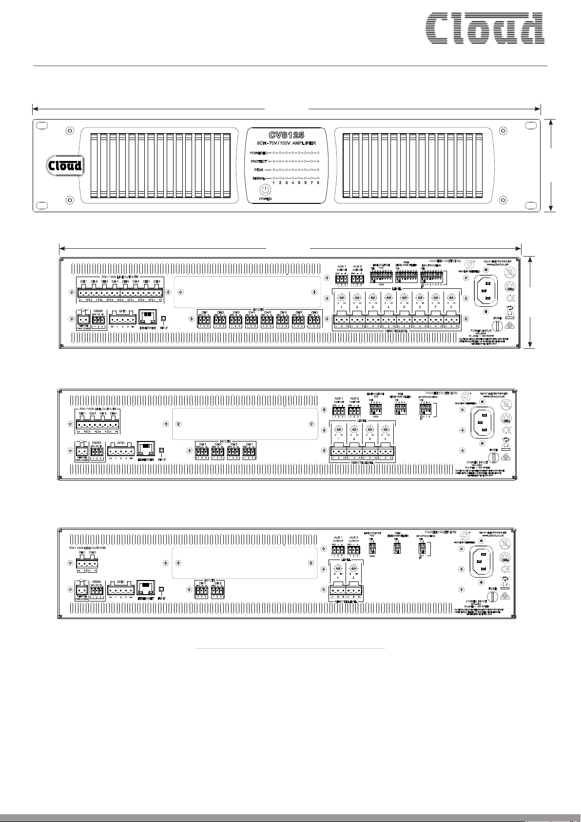
482.6 mm
19”
441.2 mm
17.4”
Cloud CV8125 - front panel view
(CV2500 & CV4250 differ only in number of LEDs)
3.4”
88 mm (1U)
3.46”
87.1 mm
Cloud CV8125 - rear panel view
Cloud CV4250 - rear panel view
Cloud CV2500 - rear panel view
General Description
Cloud CV digital amplifiers are versatile multi-channel power
amplifiers of advanced design, able to drive 70/100 V-line
loudspeaker systems directly. They are ideal for sound reinforcement
applications in the retail, leisure, hospitality, commercial or industrial
sectors. Large installations using multiple amplifiers will benefit
from the amplifiers’ network connectivity: each amplifier may be
configured individually, controlled and monitored remotely over a
standard Ethernet network.
All Cloud products are exclusively designed in the UK.
Every Cloud product is exhaustively tested for electronic performance and sonic perfection in Shefeld, England.
All models include on-board, user-configurable DSP permitting
great flexibility of internal architecture, and a wide variety of
remote control options including Ethernet, RS-232 and DC: the
latter providing compatibility with standard Cloud remote control
plates. An important aspect of the design is that “out of the box”,
the amplifiers emulate earlier Cloud amplifier designs. It is not
necessary to either connect a computer nor remove the lid to access
internal jumpers to set primary configuration parameters such as
Page 2

Clearly better sound
input routing, which may be done using rear panel DIP switches.
Where more advanced configuration options are needed, they can
be easily accessed through the internal web server and an Ethernet
connection to an external device.
Models:
The range comprises three models:
MODEL CHANNELS POWER
CV2500 2 2 x 500 W
CV4250 4 4 x 250 W
CV8125 8 8 x 125 W
The amplifiers use an energy-efficient Class D output stage which
dispenses with line output transformers, and consequently offer
great savings in weight and size over traditional designs of equivalent
power ratings. Safety features of the design include output DC
detection, overcurrent protection, and thermal monitoring. A
switch-on delay provides loudspeaker protection at power-up. All
models are built in a 2U steel enclosure, and use variable–speed
forced-air cooling.
All models have a total power output capability of 1 kW, this
maximum power rating being shared equally between odd-numbered
channels in any combination, and even-numbered channels in any
combination. Thus the odd-numbered channels can deliver a total
of 500 W and similarly, the even-numbered channels can deliver
500 W. This feature allows – for example – one multi-channel
amplifier to drive loudspeaker systems in areas of a building differing
in size, while optimising the overall power capability.
Particular design attention has been paid to the amplifiers’ energy
efficiency*. An automatic power-down (APD) feature puts the
amplifier into an ultra-low-current standby mode if no input
signal has been detected for 30 minutes; in this mode the power
consumption is approx. 2.5 W. The amplifiers also include a remote
standby/wake up function, enabling them to be placed into standby
mode - and subsequently powered-up again - by a simple external
contact closure. Wake-up time is typically 200 ms.
In addition to the “soft” power switch and associated LED, the front
panels are fitted with four LEDs for each channel: these confirm
signal presence, peak level, activation of the protection circuitry and
amplifier power status.
The inputs are electronically balanced, on plug-in multiway
connectors. Rear panel controls are provided for individual channel
levels; multi-pole DIP switches allow the configuration of input
routing options and the selection of per-channel 65 Hz high-pass
filters (to help prevent loudspeaker transformer core saturation
in 70/100 V-line systems). Further DIP switches allow selection
of 70 V-line or 100 V-line working. The rear panel also provides
two balanced, line level, auxiliary outputs which may be used to
feed low-frequency subs, additional amplifiers, for recording, or
other purposes. By default, these carry the “pre-amp out” signals
in Channels 1 and 2 respectively, but either may be extensively
reconfigured via software (see following pages).
Many more set-up options can be achieved by configuring the
amplifier’s DSP section, which uses an on-board web server. This may
be accessed via the Ethernet interface from any computer or other
device with an HTML5/CSS3-compatible browser application. DSP
functions include input routing, level, limiting, 7-band Room EQ,
hi-pass filtering, up to 1.5 s of delay and 5-band speaker optimisation
EQ. Total flexibility of input routing permits an amplifier to be easily
configured for multi-channel or parallel channel operation, biamping
with full control of crossover parameters, or derivation of a separate
channel for sub-bass use (model dependent). Additionally, it is also
possible to redefine the sources for the auxiliary outputs, which
also include Room and Speaker EQ sections, crossover filtering and
level controls. Users can determine which amplifier functions are
accessible on the hardware controls and which are only available via
the web browser interface, and there is also a password protected,
multi-user security system to define the accessibility to the various
unit functions for different users.
In addition to Ethernet remote control via the web server pages,
the amplifiers are compatible with standard Cloud RL Series remote
level control plates: each channel has a dedicated remote control
connector for this purpose. A greater degree of control is possible via
the RS-232C serial port; this allows the amplifier’s levels, channel
mutes and power-down to be readily controlled by most third-party
control systems (e.g., Crestron, AMX, etc.). Serial codes may also
be transmitted via Ethernet. A 3-way GPIO port is also provided,
which may be used as an external master mute (equivalent to the
Music Mute control input on most other Cloud products), or for fault
condition signalisation.
An optional web monitor card, the WM-n is available for all models
(where ‘n’ = the number of channels supported); this replaces the
standard speaker output card and performs scheduled, offline
impedance tests using test tones.
*ENERGY STAR certification.
Internal temperatures, amplifier power status and results of
impedance tests (when the optional WM-n card is fitted) will be
reported via the web interface and SNMP.
Page 3

Clearly better sound
Key Features
Amplifier:
• Advanced design of 2, 4 and 8-channel Class D power amplifiers
• Standard “out-of-the-box” Cloud amplifier functionality:
requires no computer configuration or internal access for basic
operation
• Transformerless output stage drives 70/100 V-line systems
directly
• Nominal power ratings: 2 x 500 W (CV2500), 4 x 250 W
(CV4250), and 8 x 125 W (CV8125)
• Thermal protection, overcurrent limiting and DC offset
protection
• Switch-on delay for speaker protection during power-up
• On 4 and 8 channel models, power sharing allows odd and even
channel groups to deliver a maximum of 500 W each
• Per-channel, front panel LEDs for signal presence, peak level,
protection activity and power status
• Balanced line level inputs
• Per-channel output level controls
• Rear panel input routing switches configure amplifier for
manual selection of multichannel, stereo or mono operation
• Rear panel switches select 70 V-line or 100 V-line output levels
• Per-channel high-pass filter (65 Hz default frequency: adjustable
in software) to protect against transformer saturation in
70/100 V-line systems
• Balanced, line level auxiliary outputs with full channel
functionality, configurable and controllable via software
• Independent Automatic Power Down on odd and even channel
groups; minimises power consumption in absence of an input
signal
• <3 W power consumption with all channels quiescent
• RS-232C serial port for remote control of all amplifier functions,
including DSP configuration
• Compatible with standard Cloud RL Series remote level control
plates (per-channel)
• Remote Power Down control input
• 3-way GPIO port for master mute function or fault reporting
• Variable speed forced-air cooling
• 2U 19” rackmounting units
DSP functions:
• On-board, per-channel DSP section providing extensive routing,
filtering, EQ and limiting for all channels including the auxiliary
outputs
• 1.5 s delay pool, freely assignable across all channels and aux
outputs
• Simple DSP configuration via on-board web server; any device
with a compatible web browser and an Ethernet connection
can be used to perform setup
• Built-in DSP crossover configurations allow amplifiers to be
easily used with 2-way speakers
• Crossover configurations allow derived LF sub output
• DSP-implemented 5-band parametric speaker EQ section
• Optional EQ presets for OEM speakers (under development)
• Password-protected multi-user security system
• Optional web monitor card performs load impedance tests and
reports out-of-tolerance results via a web interface or SNMP
Page 4
Clearly better sound
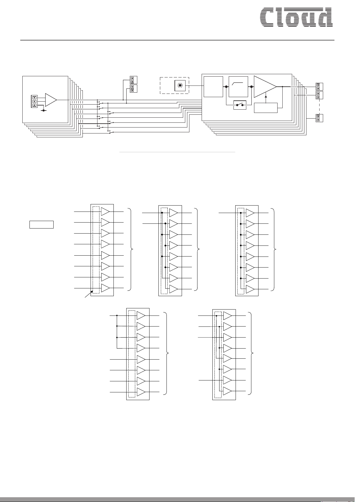
Block Diagram
SPEAKER
CHANNEL 1
AUX1
AUX2
OPTIONAL
REMOTE
LEVEL
LEVEL
CONTROL
65Hz
OUTPUTS
ROUTING
PROTECT
* 8 CHANNEL MODEL SHOWN, OTHER MODELS
HAVE REDUCED CHANNEL COUNT
ONE CHANNEL SHOWN FOR CLARITY
Input Routing
The input routing switches permit various permutations of mono, stereo and multi-channel operation without any external parallel wiring.
Some possibilities are shown below (CV8125 shown as example):
MONO PARALLEL
L (IN 1)
CV-8125
8 X MONO CHANNELS
IN 1
IN 2
IN 3
IN 4
4 x STEREO
L (IN 1)
R (IN 2)
1
2
n
IN 5
IN 6
IN 7
IN 8
INPUT ROUTING
SECTION
4 x MONO CHANNELS
+ 4 PARALLELED CHANNELS
IN 1
IN 5
IN 6
IN 7
IN 8
8 X OUTPUTS
8 X OUTPUTS
IN 1
IN 2
IN 3
IN 7
8 X OUTPUTS
+ 2 x PARALLELED CHANNELS
+ 4 x PARALLELED CHANNELS
8 X OUTPUTS
8 X OUTPUTS
2 x MONO
Although the routing options available using the rear panel switches are likely to suit most applications, even greater flexibility of routing is
available using the web browser pages, which allow any amplifier channel to be sourced from any physical input (or none) without restriction.
Page 5
Clearly better sound
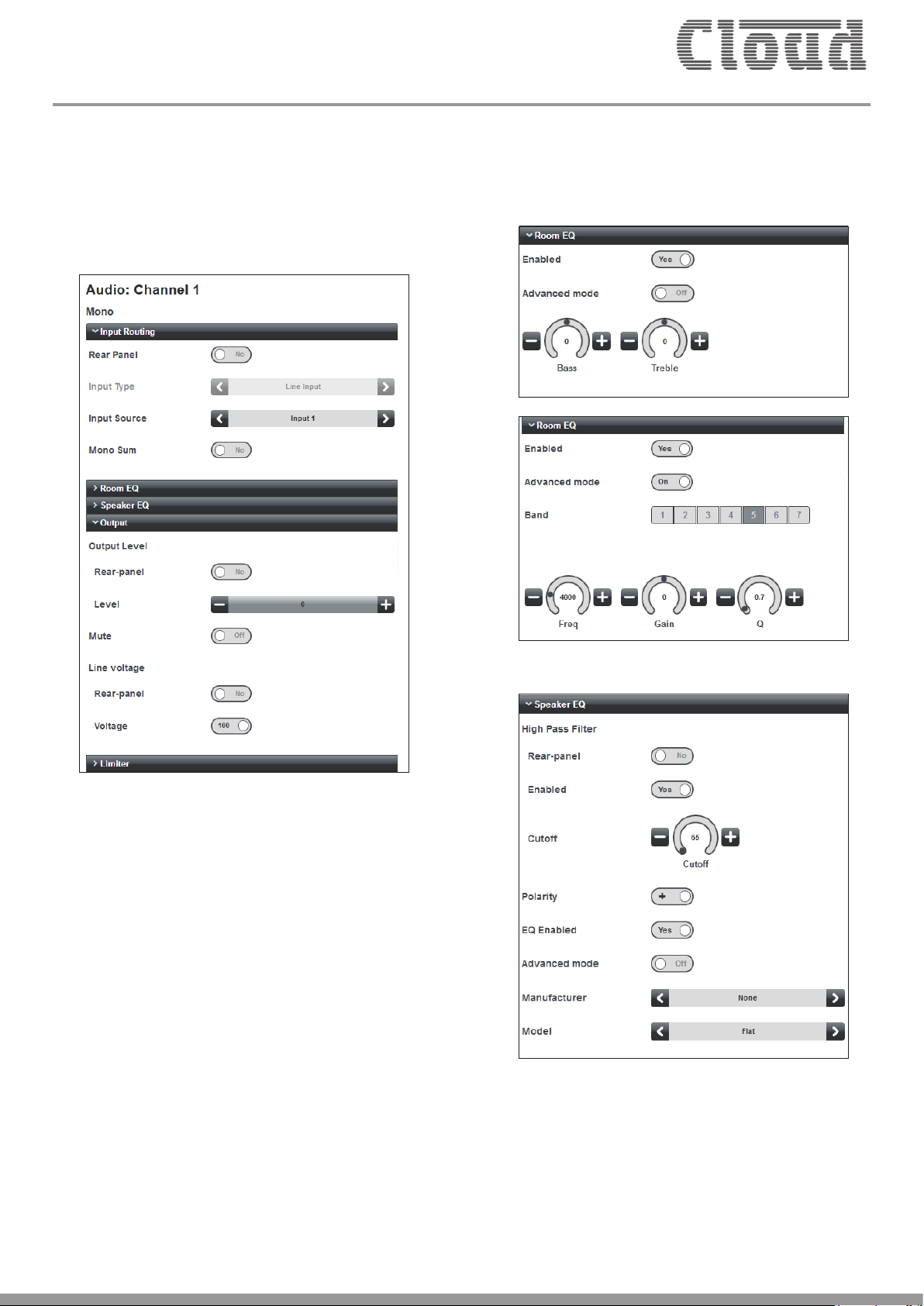
Software configuration
All models can be easily configured for specific amplification tasks
using the on-board web server via a computer (or any device with a
compatible web browser) connected to the rear panel Ethernet port.
Some examples of web browser control pages are shown below:
The EQ sections have “basic” (2-band) and “advanced” (7-band
fully parametric) modes.
Audio channel configuration allows expanded input routing options,
stereo-to-mono summing, room and loudspeaker EQ adjustment,
limiting and output level control.
Page 6

Clearly better sound
The two auxiliary outputs can be fully configured: source, level, EQ,
filtering, etc., are all available.
Up to 10 different users may given unique passwords, allowing
them control of level and/or source of certain channels.
Page 7

Clearly better sound
A total of 1482 ms of delay can be freely shared between the
main amplifier channels and the auxiliary outputs. Delay can be
assigned in terms of meters and feet as well as time.
Additionally, with the optional WM monitor card, each channel
can have its test signal frequency defined, together with load
impedance and test tolerance. Impedance tests may be scheduled
to run at user-selectable intervals and at specific times of day.
Amplifier power-on/power-off times and over-temperature are
also recorded; an event log is maintained for record-keeping
purposes.
The amplifiers have built-in fault monitoring and logging facilities.
Page 8

Clearly better sound
Application Example
The example above shows an how the eight channels of a CV8125
amplifier may be used to provide audio to different areas of a hotel.
All loudspeakers are 70/100 V-line models and the system may be
extended to additional speakers in each area as required, provided
the total 500 W power capacity of the odd/even channel groups is
not exceeded.
The Main Bar area is shown with a two-way speaker system:
Channels 1 and 2 are configured as a 2-way crossover, with filter
characteristics set according to the speaker manufacturers’
specifications.
The other areas are arranged to take advantage of the amplifier’s
odd/even channel maximum power capacity.
A Wireless Access Point is connected to the Ethernet port, allowing
control of the entire system to be achieved from a hand-held device
anywhere in the vicinity. Source selection and level control for each
zone can be adjusted using the internal web pages on any standard
browser. Only two external audio sources are shown for clarity, but
up to eight may be connected: the browser pages permit any source
to be assigned to any of the eight channels.
One of the auxiliary outputs is shown connected to a set of active
2-way speaker systems in the Ballroom; because this output is
balanced, a long cable run may be used without fear of signal loss
or interference.
Page 9

Clearly better sound
Technical Specifications
Performance
Inputs
General
All Models
Output Power Total output power 1 kW, all channels
Output Voltage 70 V or 100 V (rms)
Frequency Response 20 Hz to 20 kHz, +/-0.5 dB
High Pass Filter
-3 dB @ 65 Hz via rear panel switches
-3 dB @ 20 Hz to 200 Hz via DSP configuration
Distortion 0.03%THD @1 kHz, 1 dB below rated output
Noise -94 dB, 22 Hz to 22 kHz
< -90 dB @1 kHz, -82 dB @10 kHz adjacent channels
Crosstalk
<-107 dB @1 kHz, -93 dB @10 kHz non-adjacent channels
All tested with 125 W load
Connectors 3-pole 3.5 mm-pitch plug-in screw-terminal connectors
Sensitivity 0 dBu (0.775 V
)
rms
Input Impedance 10 kohms (balanced); 5 kohms (unbalanced)
Output connectors 2-pole 5 mm-pitch plug-in screw-terminal connectors
Remote level control connectors 3-pole 5 mm-pitch plug-in screw-terminal connectors
Compatible with Cloud RL Series remote control plates
Power input 85 to 264 V AC, 40 to 60 Hz
Mains protection Class 3T 250 V fuse, 20 x 5 mm, rating T8A
Normal Operating Temperature
0 °C to 35 °C (Note performance and specifications cannot be guaranteed outside this
range)
CV2500 CV4250 CV8125
2
Power Consumption
Standby
3
Idle
1/8th power
1/3rd power
2
Standby
2.34 W, 12.4 VA 2.43 W, 24.0 VA 2.5 W, 24.4 VA
27.1 W, 46.7 VA 38.9 W, 60.0 VA 59.7 W, 89.3 VA
4
164.2 W, 201.3 VA 187.4 W, 227.2 VA 207.0 W, 248.8 VA
5
380.7 W, 421.1 VA 330.1 W, 368.8 VA 352.6 W, 387.5 VA
8.4 KJ/hr
(8.0 BTU/hr)
3
Heat Loss
Idle
1/8th power
4
97.3 KJ/hr
(92.5 BTU/hr)
179 KJ/hr
(169.7 BTU/hr)
1/3rd power
5
293.3 KJ/hr
(278.7 BTU/hr)
1
8.7 KJ/hr
(8.3 BTU/hr)
140.1 KJ/hr
(132.9 BTU/hr)
217.9 KJ/hr
(206.7 BTU/hr)
263.5 KJ/hr
(249.9 BTU/hr)
9.1 KJ/hr
(8.7 BTU/hr)
215.0 KJ/hr
(203.9 BTU/hr)
278.7 KJ/hr
(264.3 BTU/hr)
334.4 KJ/hr
(317.1 BTU/hr)
Page 10

Clearly better sound
Technical Specifications (continued)
General (continued)
Overcurrent
Amplifier Protection
Status Indicators Power applied, Protection active, Signal peak, and Signal present
Cooling Variable speed fan
Dimensions
(W x H x D)
Weight
Net 482.6 mm x 88 mm x 381.8 mm (19 in x 3.46 in x 15.03 in)
Shipping 606 mm x 164 mm x 558 mm (23.9 in x 6.5 in x 22 in)
Net 6.86 kg
Shipping 8.86 kg
1. Odd- and even-numbered channel groups can deliver up to 500 W simultaneously, but in models with more than two channels, the
available power is reduced proportionately when any channel is delivering more than its nominal rating.
Notes re Power Consumption and Heat Loss measurements: All measurements at 230 VAC 50 Hz power input
2. Standby: amplifier in standby state
3. Idle: amplifier not in standby state, but no audio output
4. 1/8th Power: constant sound level at 1/8 of the rated output power (audio mainly clean, only occasional clipping)
5. 1/3rd Power: constant sound level at 1/3 of the rated output power (audio beginning to become compressed, limited or heavily clipped)
DC
Thermal monitoring
Switch-on delay
CV2500 CV4250 CV8125
(15.37 lb)
(19.85 lb)
7.26 kg
(16.26 lb)
9.26 kg
(20.74 lb)
8.05 kg
(18.03 lb)
10.05 kg
(22.51 lb)
Energy Star certificate web link: http://www.ul.com/customer-resources/ul-energy-efficient-product-database/
UL Energy Efficient Product Database.
Page 11

Clearly better sound
Performance Graphs
Hz
Hz
Hz
Frequency Response Open Circuit Frequency Response
+10
+9
+8
+7
+6
+5
+4
+3
+2
+1
d
-0
B
r
-1
-2
-3
-4
-5
-6
-7
-8
-9
-10
20 20k 50 100 200 500 1k 2k 5k 10k
Crosstalk Performance, Ch1 to Ch2, Ch1 @100V O/P into 80 Ohms
+0
-10
-20
-30
-40
-50
-60
d
-70
B
r
-80
-90
-100
-110
-120
-130
-140
20 20k 50 100 200 500 1k 2k 5k 10k
Frequency Response, Ch1 into 80 Ohms
Crosstalk Ch1 to Ch2 THD+N
+10
+9
+8
+7
+6
+5
+4
+3
+2
+1
d
-0
B
r
-1
-2
-3
-4
-5
-6
-7
-8
-9
-10
20 20k 50 100 200 500 1k 2k 5k 10k
Frequency Response, Ch1 No Load
THD+N % VS Output Power into 80 Ohms
0.2
0.1
0.08
0.07
0.06
0.05
0.04
%
0.03
0.02
0.01
0.008
0.007
0.006
2
20
W
40
30
50 607080
1003 4 567 8 9 10
Page 12

Clearly better sound
Architect’s and Engineer’s Specification
The power amplifiers shall be available in two channel, four
channel and eight channel versions. The output stage shall be
a transformerless constant voltage type suitable for driving
70 V-line or 100 V-line loudspeaker systems. Each amplifier shall
have two groups of channels with a total of 500 watts available
from each group: the even numbered channels shall form one group,
the odd channels a second group.
The amplifiers will include an automatic power-down (APD) feature
which will shut down either group of channels that has not received
an input signal for thirty minutes.
The amplifiers’ front panels shall incorporate a “soft” AC power
switch, an LED indicating POWER ON, and LEDs indicating Signal
Present, Peak Level, Protect status and Power status for each
channel. The Signal Present LEDs shall illuminate when the output
level is 30 dB below the rated output. The Peak LEDs shall illuminate
at the onset of signal clipping. The Protect LEDs shall indicate
activation of the channel protection circuitry. The Power status LEDs
shall indicate that the channel has not been powered down by the
APD system.
The amplifiers shall be provided with a number of inputs equal to
the number of channels. The input connectors shall be of removable,
screw-terminal type. The inputs shall be electronically balanced and
capable of operating with both balanced and unbalanced sources.
The input impedance shall be 10 kohms (balanced). It shall be
possible to configure the amplifiers to operate in the following
configurations as a minimum: all channels independent, one input
feeding all channels or two inputs feeding the amplifier channels in
pairs for stereo operation. It shall be possible to enable a high-pass
3rd order filter with a turnover frequency of 65 Hz independently
in each amplifier channel. The amplifiers shall be provided with
externally accessible switches for setting each channel to operate
with 70 V-line or 100 V-line systems independently. It shall be
possible to select all the configurations and settings described in this
paragraph without accessing the interior of the amplifier enclosure,
and without connecting an external device.
Output level adjustment will be provided for each amplifier channel
via a rear panel control: at the minimum setting, the channel shall
be muted. Each channel shall deliver its rated power from an input
signal of 0 dBu with the channel level control set at maximum.
Output mute protection on power-up and thermal protection shall
be provided. The amplifiers will also be protected against short
circuits at the output, and excessive combination of output voltage
and current. The amplifiers’ outputs shall be on removable, screw
terminal connectors.
The amplifiers shall include a digital signal processing (DSP) section:
this shall be controllable through a series of web pages stored
internally which shall be accessible on a web browser application
on an external computer or similar device connected to a standard
Ethernet port.
The DSP section shall provide the following facilities as a minimum:
i) configuration of amplifier channels for mono, stereo, mono or stereo
bi-amping with or without a separate LF sub output; the availability
of these configurations shall be restricted according to the number
of amplifier channels; ii) an input matrix section permitting any input
to feed any amplifier channel without restriction, iii) equalisation
for each channel: this shall have a minimum of seven bands and be
of the fully parametric type; the highest and lowest frequency bands
shall be selectable to bell or shelf modes; iv) a further equalisation
section for each channel capable of optimising the channel for use
with a selection of popular loudspeakers specific to commercial
sound applications by both the selection of a loudspeaker-specific
preset, and by the use of a equaliser of the parametric type with
a minimum of five frequency bands; v) a limiter section in each
channel, with threshold adjustment; vi) control of output level,
lowpass filtering and polarity of each auxiliary output.
There shall be at least two balanced line level auxiliary outputs on
removable, screw-terminal connectors. It shall be possible for the
source of each auxiliary output to be selectable from any of the
amplifier’s main channels, and each output shall include the same
equalisation and limiter capabilities as the amplifier’s main channels.
Each auxiliary output shall also include a filter section to permit the
configuration of loudspeaker crossover filters, with choice of filter
type and slope.
It shall be possible to apply a time delay to any or all channels and/
or auxiliary outputs. The total delay available shall not be less than
1.482 seconds, and it shall be possible to freely share this maximum
delay between all channels and/or auxiliary outputs. It shall be
possible to assign the delay in units of either time or distance (both
metric and imperial).
The amplifier shall maintain an internal log of amplifier powerup and power-down times, occurrences of over-temperature, plus
impedance test results if the load monitoring option is fitted.
Load impedance monitoring shall be available as an option on all
versions. It shall be possible to specify test frequency for each
channel and also the dates and times of load testing.
An optional remote control shall be available for any or all amplifier
channels, to allow adjustment of channel level. The remote control
connector shall be of removable, screw-terminal type. The amplifiers
shall be equipped with a bi-directional serial control port to
RS-232C standards: all amplifier and DSP functions shall be
controllable via this port.
The amplifier shall be built in a steel chassis suitable for mounting in
a standard 19” equipment rack, and occupy two rack spaces. Variable
speed forced-air cooling shall be employed; the fan shall not operate
unless the internal temperature dictates it.
The amplifiers shall operate on all AC supply voltages between
85 V and 264 V. They shall be compliant with the relevant provisions
of EnergyStar® Eligibility Criteria Ver. 3.0 for Audio-Video Products.
In the absence of an input signal, they shall automatically enter
“standby” mode wherein the DC power consumption shall be less
than 3 W. It shall also be possible to control the power status of the
amplifiers via a dedicated control input with an external contact
closure.
The power amplifiers shall be the Cloud CV2500 (two channels),
CV4250 (four channels), and CV8125 (eight channels).The load
impedance monitoring option shall be the Cloud WM-2 (two
channels), WM-4 (four channels) and WM-8 (eight channels). The
remote level control plate shall be the Cloud RL-1 Series.
Page 13

Clearly better sound
Page 14

Clearly better sound
www.cloud.co.uk www.cloudusa.pro
E&OEIssue_2.1
 Loading...