

Page 1
CDI-46 Installation and Setup Guide V1.3
CDI-46
SERIAL INTERFACE CARD
Installation and Setup Guide
Page 2

CDI-46 Installation and Setup Guide V1.3
2
Contents
Introduction .................................................................................................................................... 3
Scope of this Guide ....................................................................................................................................................... 3
What’s in the box .......................................................................................................................................................... 3
Installation ...................................................................................................................................... 4
Mechanical tting and internal connections ............................................................................................................. 4
CDI-46 jumper settings ................................................................................................................................................ 6
Using the Digital Paging Interface ................................................................................................ 6
Remote Control of the 46-120 via Ethernet ................................................................................ 7
OS and Browser compatibility .................................................................................................................................... 7
Checking browser compatibility ............................................................................................................................. 7
Conguring the network.............................................................................................................................................. 8
46-120 browser control ............................................................................................................................................. 10
Zone Settings .............................................................................................................................................................10
Paging Control ...........................................................................................................................................................11
Conguration options .............................................................................................................................................12
Zone/Source Matrix ................................................................................................................................................. 12
Zone Control ............................................................................................................................................................ 13
Level and Source Visibility ....................................................................................................................................... 13
CDI Control ..............................................................................................................................................................13
Labelling ...................................................................................................................................................................... 14
System Defaults ........................................................................................................................................................16
Power-up Mode and Power-up Defaults .............................................................................................................. 16
RS-232 Baud Rate ..................................................................................................................................................... 16
Network ..................................................................................................................................................................... 16
Device Info ................................................................................................................................................................. 17
Firmware update .......................................................................................................................................................18
Change Installer PIN ................................................................................................................................................ 18
User Security ............................................................................................................................................................. 19
Documents .................................................................................................................................................................22
Music Mute .................................................................................................................................................................22
46-120 Serial Control ................................................................................................................... 23
Abridged command set ........................................................................................................................................... 24
Examples ..................................................................................................................................................................... 24
Using the CDI-46 as an Ethernet-to-serial bridge ............................................................................................ 26
Cable lengths ............................................................................................................................................................. 26
Page 3

CDI-46 Installation and Setup Guide V1.3
3
Introduction
The CDI-46 is an optional digital interface card designed specically for use with the Cloud 46-120 range of
Multi-Zone Mixer Ampliers. The card has an Ethernet port and an RS-232 port, allowing the Mixer Amplier’s primary functions
to be controlled from external systems (Crestron, AMX, etc.) using the Cloud Serial Protocol, via either an Ethernet network
link or an RS-232 serial interface. The card can also act as an Ethernet-to-serial bridge, converting Ethernet commands from a
control system into RS-232 data for other non-Ethernet equipped equipment (e.g., projectors).
The CDI-46 is also tted with a Cloud Digital Paging interface (the CDPM/PM INPUT). This provides the simplest method of
connecting Cloud PM Series Paging Microphones, requiring only a single standard Cat 5 cable.
When installed, the CDI-46 permits the following 46-120 functions to be controlled remotely:
1. Music source selection for each zone
2. Music level in each zone
3. Music muting in each zone
4. Muting of individual microphones in each zone
5. Activation of Mic 1’s paging access
6. Triggering of messages stored in a PM-SA paging microphone
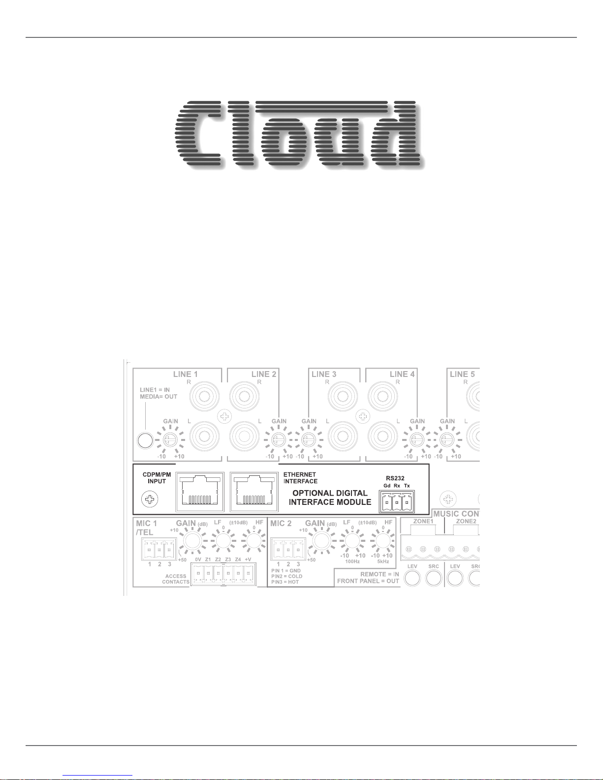
Physically, the CDI-46 is a small printed circuit board (PCB), which is retrotted internally in the 46-120 such that the
ETHERNET INTERFACE, CDPM/PM INPUT and RS-232 connectors are available at the rear panel.
Scope of this Guide
This manual describes the mechanical installation of the card and the connections that need to be made to it. It also explains
the various conguration options that the card offers, and how to set these using the simple built-in web server, and the various
jumper settings that need to be made to the 46-120 to achieve correct operation.
The manual also gives a general overview of the Cloud Serial Protocol as used by the CDI-46, and some examples of the most
useful commands. This information should be adequate for many installations, but please note that a full description of the
protocol is beyond the scope of this manual. The full CDI-46 Serial Control Protocol document is available in PDF format via
the browser interface; alternatively, it can be downloaded from www.cloud.co.uk.
What’s in the box
• CDI-46 PCB
• Installation Guide (this document)
• Mating 3-pin 3.5 mm-pitch screw-terminal connector (for RS-232)
• 2 qty M3 x 15 mm mounting pillars
• 2 qty M3 x 6 mm black pan-head screws
NOTE: The CDI-46 is applicable throughout the 46-120 range, which comprises four models: 46-120, 46-120MEDIA, 46-120T
and 46-120TMEDIA. Throughout this Guide, we refer simply to the host unit as the “46-120”; this can be taken to apply to all
models, unless specically stated otherwise.
Page 4
CDI-46 Installation and Setup Guide V1.3
4
Installation
Mechanical tting and internal connections
Fit the CDI-46 card within the 46-120 host unit according to the instructions below:
1. Disconnect the 46-120 from the AC mains.
2. If the 46-120 is installed in an equipment rack, disconnect all audio and control wiring, remove the unit from the rack and
place on a convenient at surface.
3. Remove the top cover (10 screws) and orientate the unit with the rear panel towards you.
4. Remove the adhesive label covering the empty connector holes from the rear panel.
J2
(below sub-board)
LINE INPUT SUB-BOARD
CON21
CON22 CON25
CON23
CON13
REAR LH SECTION OF
46-120 MAIN PCB
NOT TO SCALE – FOR
COMPONENT LOCATION
PURPOSES ONLY
REMOVE M3
SCREW
REMOVE M3
SCREW
REMOVE
JUMPERS
REMOVE
JUMPERS
J7
J10 - J13
J1
J17
J5
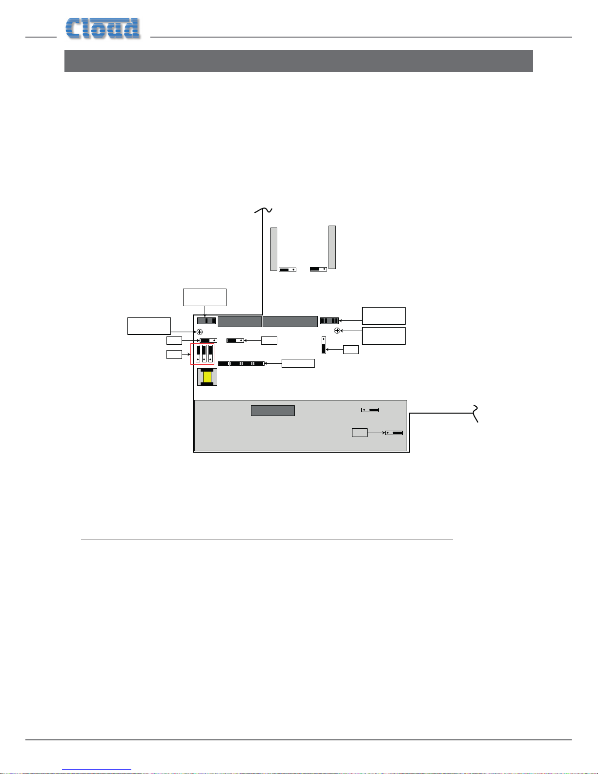
5. Refer to the 46-120 main PCB layout diagram above. Note that there are several jumpers on the PCB which will be not
readily accessible once the CDI-46 card is installed (i.e., the card will need to be removed to access them). Therefore
installers should ensure that these jumpers are set as required BEFORE tting the CDI-46.
Note that J10 to J13 MUST be removed for the CDI-46’s Digital Paging Interface to operate correctly. If the CDI-46 is being
installed purely for remote control purposes (and not paging), they can stay in place.
Page 5
CDI-46 Installation and Setup Guide V1.3
5
The jumpers concerned, and their functions, are listed below:
JUMPER DESCRIPTION EFFECT DEFAULT
J1 Mic 1 phantom power
OFF: MIC 1 phantom power OFF
ON; MIC 1 phantom power ON
OFF
J2 Mic 2 phantom power
OFF: MIC 2 phantom power OFF
ON: MIC 2 phantom power ON
OFF
J5 Music Mute contacts
N/O: contact closure required for muting
N/C: contact opening required for muting
N/O
J7 Mic over Facility input priority
OFF: No priority
ON: MIC 1 & 2 have VOX-triggered priority over signals at facility port
OFF
J10 Mic1, Zone 1 Access Bypass
PRESENT: Mic has permanent access to Z1
ABSENT: Use access port to enable access to Z1
PRESENT
J11 Mic1, Zone 2 Access Bypass
PRESENT: Mic has permanent access to Z2
ABSENT: Use access port to enable access to Z2
PRESENT
J12 Mic1, Zone 3 Access Bypass
PRESENT: Mic has permanent access to Z3
ABSENT: Use access port to enable access to Z3
PRESENT
J13 Mic1, Zone 3 Access Bypass
PRESENT: Mic has permanent access to Z4
ABSENT: Use access port to enable access to Z4
PRESENT
J17A, B, C* MIC 1/TEL input transformer
OFF: MIC 1 input accepts standard mics
ON: MIC 1 input suitable for connection to telephone system
OFF
* J17 A, B & C must be moved together.
6. Unplug the 20-pin ribbon cable from CON13 on the line input sub-board (immediately behind the line input phono sockets).
7. Remove the two M3 screws identied on the diagram above from the main PCB (adjacent to CON21 and CON23).
8. Replace the screws with the M3x15 hex pillars supplied with the card.
9. Using small pliers, remove the two jumpers from header CON21 and the four from header CON23 (both on the main
PCB).
10. Hold the CDI-46 card upside-down so that its connectors are facing the front of the chassis. Note that it is supplied with
four ribbon cables already tted; three of these now project towards the rear of the chassis. Plug the 10-way ribbon cable
coming from CON8 on the CDI-46 card (this one is the left-most of the three) into header CON21 on the main PCB. The
red ident on the ribbon cable should be to the right.
11. Plug the 20-way ribbon cable from CON7 on the CDI-46 card (the middle one) into header CON22 on the main PCB. The
free connector can only go in one way.
12. Plug the 10-way ribbon cable from CON5 on the CDI-46 card (the right-most one) into header CON23 on the main PCB.
The red ident on the ribbon cable should be to the right.
13. Now turn the CDI-46 card the right way up and position it below the line input sub-board so that the three connectors
and two tapped M3 holes align with the empty holes on the rear panel. The two hex pillars should align with the two holes
in the rear of the card.
14. Fix the card in place: use the two M3 screws removed in Step 7 to secure the rear to the hex pillars and the two black M3
screws supplied with the card to x the connector end of the card to the 46-120 rear panel.
15. Plug the remaining free ribbon cable from the CDI-46 (from CON4 on the card) into the now-empty CON13 on the line
input sub-board.
16. Plug the 20-way ribbon cable which was unplugged in Step 6 into the empty CON6 at the rear of the CDI-46 card.
17. Replace the top cover using the same screws (Step 3).
IMPORTANT – for the CDI-46 to control the 46-120’s music level and source selection via browser pages, or via serial
control using either RS-232 or Ethernet, it is necessary to set the rear panel MUSIC CONTROL buttons to REMOTE
(buttons ‘in’). If the CDI-46 is to have full control over music source and level in all four Zones, then all eight buttons should
be set to REMOTE. However, because the 46-120 allows independent local/remote selection for each Zone/music function
combination, it is also possible to let the CDI-46 provide full or partial remote control in some Zones, but retain front panel
control for others.
See also “Zone Settings” on page 10.
Page 6
CDI-46 Installation and Setup Guide V1.3
6
CDI-46 jumper settings
The CDI-46 has three PCB jumpers: J1, J2 and J3.
IMPORTANT: It should never be necessary to move any of the CDI-46’s jumpers under normal circumstances.
Installers are strongly advised to contact Cloud’s Technical Dept. at technical@cloud.co.uk in the event of a problem.
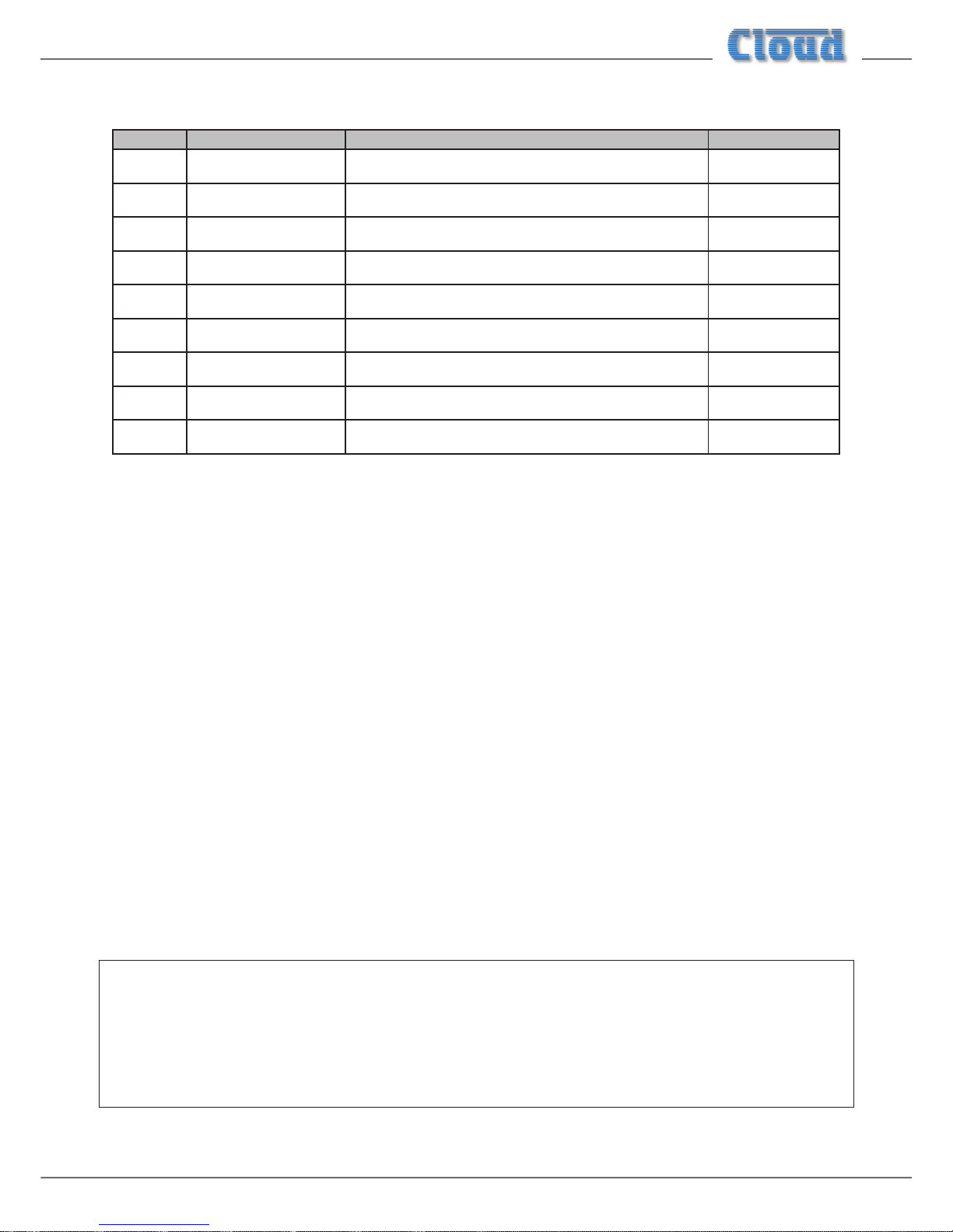
JUMPER DESCRIPTION EFFECT DEFAULT
J1 PM microphone termination
ON: 46-120 is at end of network “chain”
OFF: Special circumstances only
ON
J2
Forces CDI-46 boot load
mode
OFF: Normal operation
ON: Special circumstances only
OFF
J3 Reset internal NVM memory
OFF: Normal operation
ON: Restores all factory default settings
OFF
Using the Digital Paging Interface
The CDI-46 is tted with a Cloud Digital Paging Interface; this uses the CDPM/PM INPUT RJ45 socket. When tted, the
CDPM/PM interface uses the same signal path within the 46/120 as Mic 1, and therefore the front-panel MIC 1 Level controls,
and rear-panel MIC 1/TEL GAIN, LF and HF EQ controls should be adjusted to obtain the correct paging level in each zone.
Cloud PM Series Paging microphones may be connected directly to the CDPM/PM INPUT with Cat 5 cable; the single
connection provides all audio, control and power required by the microphone. (Note that this connector has no LEDs.)
The CDPM/PM INPUT port is able to supply 250 mA* to power paging microphones. This is adequate to power one or
two microphones of models PM-4, PM-8 or PM-12. Cloud recommend that PM-16 microphones, and all ‘-SA’ models (with
spot announcement sound stores) are powered by a separate, external PSU, as described in the PM Series Installation Guide.
(A suitable PSU is supplied as standard with all ‘-SA’ models.)
As the 46-120 only supports four zones, it is likely that a PM-4 or PM-4SA will be the models most used. If multiple 46-120s are
in use to cover a larger number of zones, the analogue interfaces on the PM and the 46-120 should be used instead. Please refer
to the 46-120 Installation and User Guide for information regarding the use of the analogue interface.
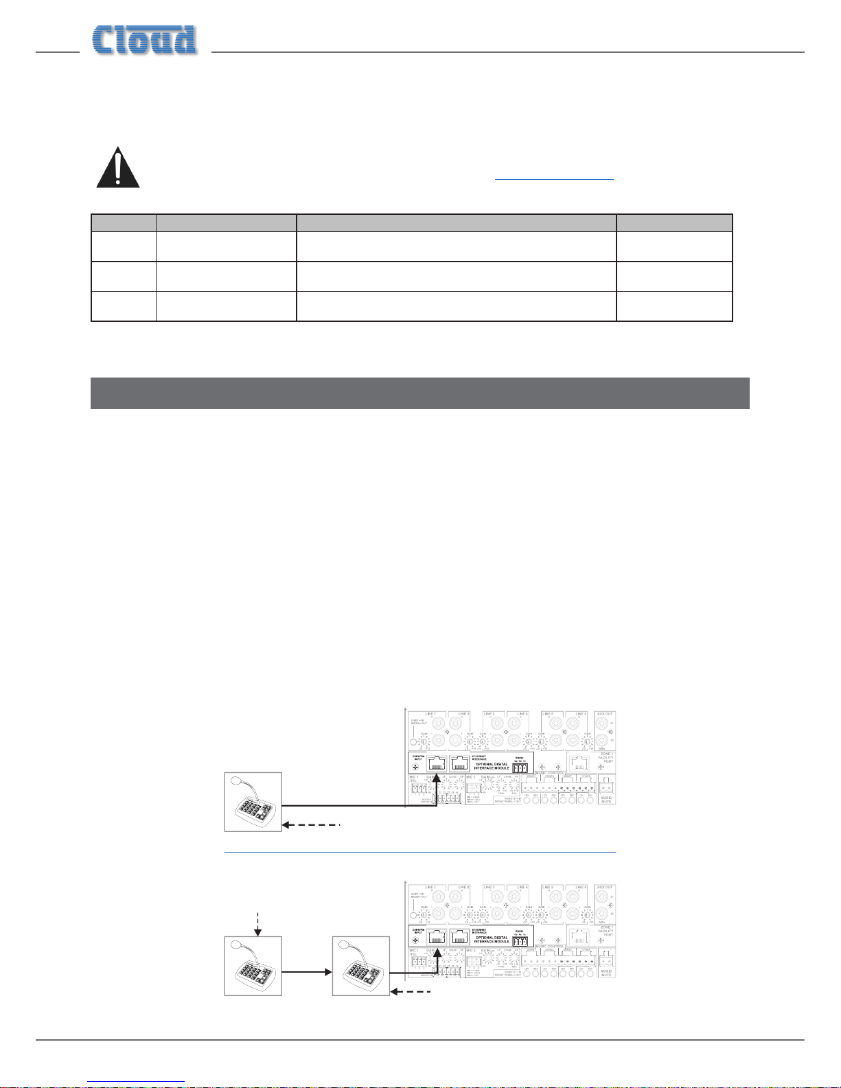
Connect the OUT socket of the PM Series microphone to the CDPM/PM INPUT socket of the CDI-46 with Cat 5 cable.
If more than one paging microphone is in use – typically at different locations in the building – the microphones should be “daisychained”, with the OUT socket of one being wired to the IN socket of the next.
46-120
INOUT
OUT
46-120
OUT
Termination ON
Termination OFF
Termination
ON
* This gure should be reduced at elevated temperatures by approximately 3 mA/°C above 23°C.
Page 7

CDI-46 Installation and Setup Guide V1.3
7
IMPORTANT – Please refer to the PM Series Installation Guide for full information regarding maximum cable length, buss
terminations and current requirements.
The earlier Cloud CDPM Series of paging microphones is also compatible with the Digital Paging Interface.
Remote Control of the 46-120 via Ethernet
The CDI-46 has a server function, which makes control pages available in a browser running on any device on the same network
as the card. This permits simple and elegant real-time control of the 46-120 from any convenient device on the network.
OS and Browser compatibility
The CDI-46’s Ethernet feature set is compatible with PCs running Windows® Vista, 7 or 8, and Apple® Mac® computers
running OSX 10.6 (Snow Leopard) upwards.
The CDI-46 will also run correctly with Windows XP, but please note that Cloud is unable to recommend this Operating
System as it is no longer supported by Microsoft.
Installers should appreciate that due to the frequency of browser updates, it is impossible to provide a denitive list of compatible
browser versions. However, at the time of creating this Installation Guide, the CDI-46 has been tested to operate satisfactorily
with the following browsers:
• Internet Explorer 11
• Chrome v.42
• Firefox v.35
• Safari v.8.02
Earlier versions of the above browsers, and some versions of other browsers, may also work correctly, though no guarantee
can be given.
Similarly, though Cloud expects that later versions of the above browsers will be satisfactory, no guarantee can be given.
Checking browser compatibility
The CDI-46 server pages use HTML5 and CSS3, which should be implemented on most recent browser versions. The HTML
features used are as follows:
• localStorage
• Forms
• Input type=number
• Elements
• Section elements
• “hidden” attribute
If there is any doubt regarding browser compatibility, Cloud recommends the use of the website html5test.com to check which
features your browser supports.
Page 8
CDI-46 Installation and Setup Guide V1.3
8
Conguring the network
NOTE: This section of the manual is intended for those with a working understanding of basic computer network conguration
and the terminology involved.
Ethernet connection to the CDI-46 can be simplied by the use of the Cloud Ethernet Discovery Tool. This can be downloaded
from www.cloud.co.uk; navigate to Products and select 46-120 4 Zone Integrated Mixer Amplier; the Tool is
available for download in the Downloads panel. The Discovery Tool is available in two distinct versions:
• an executable JAR le, which will run on Linux, Windows® or Mac® systems within a Java Runtime Environment (available
from www.java.com)
• a Windows-specic application, which does not require Java.
Download the most appropriate version for your operating system, and save it in a convenient location.
During initial setup, the CDI-46 may be connected directly to a laptop Ethernet interface, using either a straight or crossover
Ethernet cable. In this scenario, both the laptop and CDI-46 will congure themselves using Link-local IP addresses and will be
able to communicate without the requirement for DHCP, or further network infrastructure. Using this temporary connection,
the CDI-46 can be set up and congured to use either DHCP (the default) or a specic, static IP address suitable for the target
network. If a static IP address is to be used, Subnet Mask and Gateway must also be set correctly. If Gateway details are unknown,
the value 0.0.0.0 can be used safely.
Alternatively, the CDI-46 card may be connected to a spare port of an Ethernet switch on an existing network, and set up from
any device on the same network. In this scenario, DHCP is the expected method for IP address allocation during the initial
setup procedure. If the network does not support DHCP, then the direct-connection method described above should be used
to assign the correct static IP address rst.
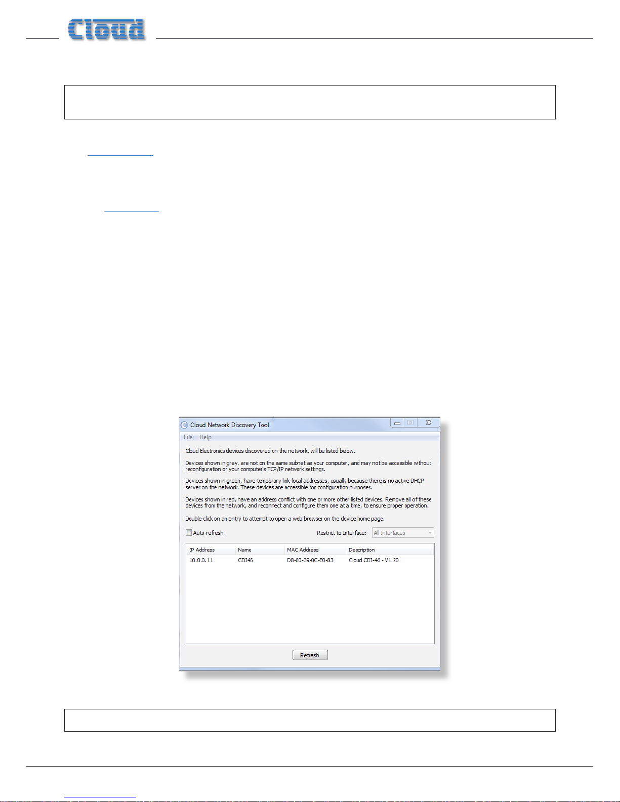
Run the Discovery Tool; this will open the window shown below, which should contain an entry with the host name CDI-46.
NOTE: If a warning message appears referencing Windows Firewall, it can be safely ignored by closing the message box.
Page 9
CDI-46 Installation and Setup Guide V1.3
9
Double-click on the CDI-46 entry. This should open your default browser and make the CDI-46’s web pages visible.
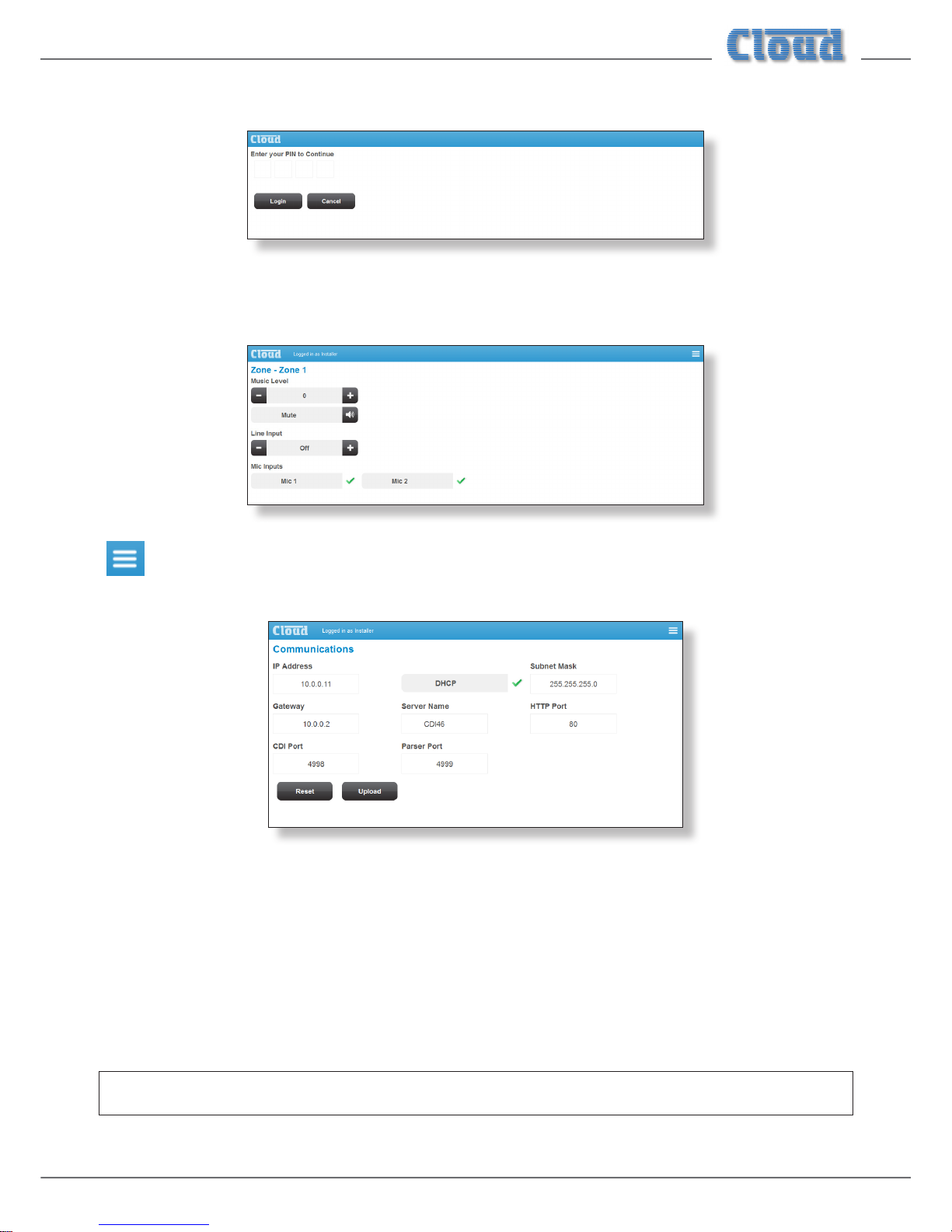
The rst page to be displayed on initial connection will be the PIN entry page; enter the Installer PIN (the factory default is
1234*) to authorise access. Click Login and the Zone 1 Settings page will be displayed.
Click the menu icon at the right hand end of the blue Cloud banner and now select Cong, followed by
Network. This will open the Communications page:
* It is recommended that the factory default PIN is changed to something less obvious when installation is complete.
We recommend that the CDI-46 should either be set with a static IP address (i.e., with DHCP disabled), or uses a xed DHCP
allocated-address on your routing hardware. It will then have a xed IP address on the network for other devices to browse to.
Ensure that a suitable IP address is reserved on the network to which you intend to connect the device. If the CDI-46 changes
IP address, users or third-party control applications may not be able to locate it. (Installers may need to consult the client’s IT
Manager for guidance.)
Note that when DHCP is enabled, values in the IP Address, Subnet Mask and Gateway elds are set automatically and
the elds are no longer modiable.
NOTE: For security, the server has a time-out of one minute; if no browser activity occurs within this time, it reverts to the
login page and the PIN will need to be re-entered.
Page 10

CDI-46 Installation and Setup Guide V1.3
10
46-120 browser control
Once the network has been set up as described above, many of the 46-120’s primary functions may be controlled remotely from
a web browser running on a computer or other device anywhere on the same network.
IMPORTANT – for the CDI-46 to control the 46-120’s music level and source selection via browser pages, or via serial
control using either RS-232 or Ethernet, it is necessary to set the rear panel MUSIC CONTROL buttons to REMOTE
(buttons ‘in’). If the CDI-46 is to have full control over music source and level in all four Zones, then all eight buttons should
be set to REMOTE. However, because the 46-120 allows independent local/remote selection for each Zone/music function
combination, it is also possible to let the CDI-46 provide full or partial remote control in some Zones, but retain front panel
control for others.
Zone Settings
The Zone Settings page allows adjustment of the primary zone functions. If the Zone has been renamed (see “Labelling” on page
14), the Zone’s name will be displayed at the top of the page instead of the number.
• Music Level – click the + and – buttons to adjust the music volume in the selected zone. A Mute/Unmute button is
also provided.
• Line Input – click the + and – buttons to select the music source (line input) for the Zone. Note that Off is the
default option, and that this is ‘above’ Line 6, so the - button must be used to access the sources from the default. If the
line inputs have been renamed (see page 14), their names will be displayed instead of Line Input n. Only Line inputs
enabled for the Zone (see page 12) will be available in the button.
• Mic Input – these two buttons force microphone access for MIC 1 and MIC 2 inputs respectively for the selected
Zone. For Mic 1, this effectively overrides the ACCESS CONTACTS port and the input will always be “live”. As with
the line inputs, if the mic inputs have been renamed their names will be displayed instead of Mic 1 and Mic 2.
NOTE: Adjustment of either Music Level or Line Input via the Zone Settings page will automatically assign the CDI-46 to “take
control” of that function in that Zone. The implication of this is that if an RL Series hardware remote control plate is connected
in the same Zone, it will become inoperative as soon as a level adjustment (or mute) is made via the browser. Similarly, in the
case of an RSL Series plate, either its level control or source selection function will become inoperative when the corresponding
adjustment is made from the browser.
It is possible to remove any of the above elements – Music Level, Line Input and Mic Input - from the Zone Settings page on a
per-Zone basis. See page 12 and page 13 for details of how to do this.
Click the menu icon at any time to return to the main menu, or the ‘Back’ button in your browser to go to the previous
page.
Page 11

CDI-46 Installation and Setup Guide V1.3
11
To select a different Zone, click Zones in the main menu, and then select the required Zone.
Paging Control
Click Paging on the main Menu to display the Paging page.
• Paging – the default red crosses against each of these four indicators change to green ticks when a Zone is selected via
the Digital Paging interface. This applies to either paging, or spot announcements from a PM-SA microphone.
• PMSA Messages – clicking on the arrows (>) of these eight buttons sends a command to a Cloud PM-SA Series
paging microphone connected to the Digital Paging Interface to trigger one of its spot announcement groups. Each group
denes a set of zones, a specic chime and a pre-recorded message to be played in those zones. Model PM4-SA has four
programmable spot announcement groups (A to D), while Model PM-8SA has eight (A to H). If the groups have been
renamed (see page 14), their names will be displayed instead of Group X.
Page 12
CDI-46 Installation and Setup Guide V1.3
12
Conguration options
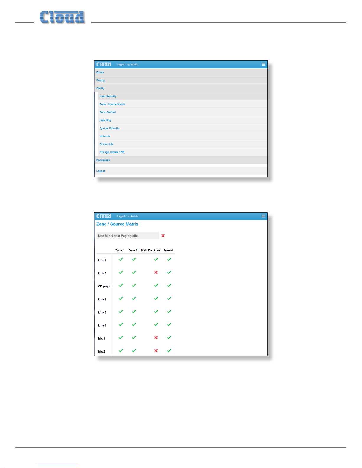
The various setup and conguration options are accessed by clicking the Cong tab on the main Menu.
Zone/Source Matrix
Normally (i.e., without a CDI-46 card tted), all six music sources (line inputs) in the 46-120 and both mic inputs are fully
available to all four Zones, and are selected either by the front panel controls or by RSL Series remote control plates installed
in the Zones themselves. When controlling the 46-120 from the browser interface, it is possible to restrict the available sources
in each Zone. The Zone / Source Matrix page lets the installer determine which line and mic inputs are available to each
Zone via the browser.
The default is for all inputs to be available to all Zones, as denoted by the green ticks. Click on a tick to deselect a source in a
particular Zone: the tick changes to a red cross. Deselected music sources will now not appear in the list in the Line Input
button on the relevant Zone Settings pages, and a deselected mic input will have its button removed from the page.
Page 13
CDI-46 Installation and Setup Guide V1.3
13
As elsewhere, line inputs and Zones that have been renamed will have their names displayed in the Zone/Source Matrix instead
of numbers.
Use Mic 1 as a Paging Mic – this function is disabled as default; click the red cross if MIC 1 INPUT is to be used
for paging purposes (as opposed to a per-zone mic for e.g., karaoke). Once enabled for paging, the Mic 1 row in the matrix is
removed, and the Mic 1 buttons on the four Zone Settings pages are also removed.
NOTE: The Zone / Source Matrix page only affects source selection options in the browser interface. All sources
remain available to all zones when using the front panel controls, RSL remote control plates or through serial commands
received at either the RS-232 port or the Ethernet port.
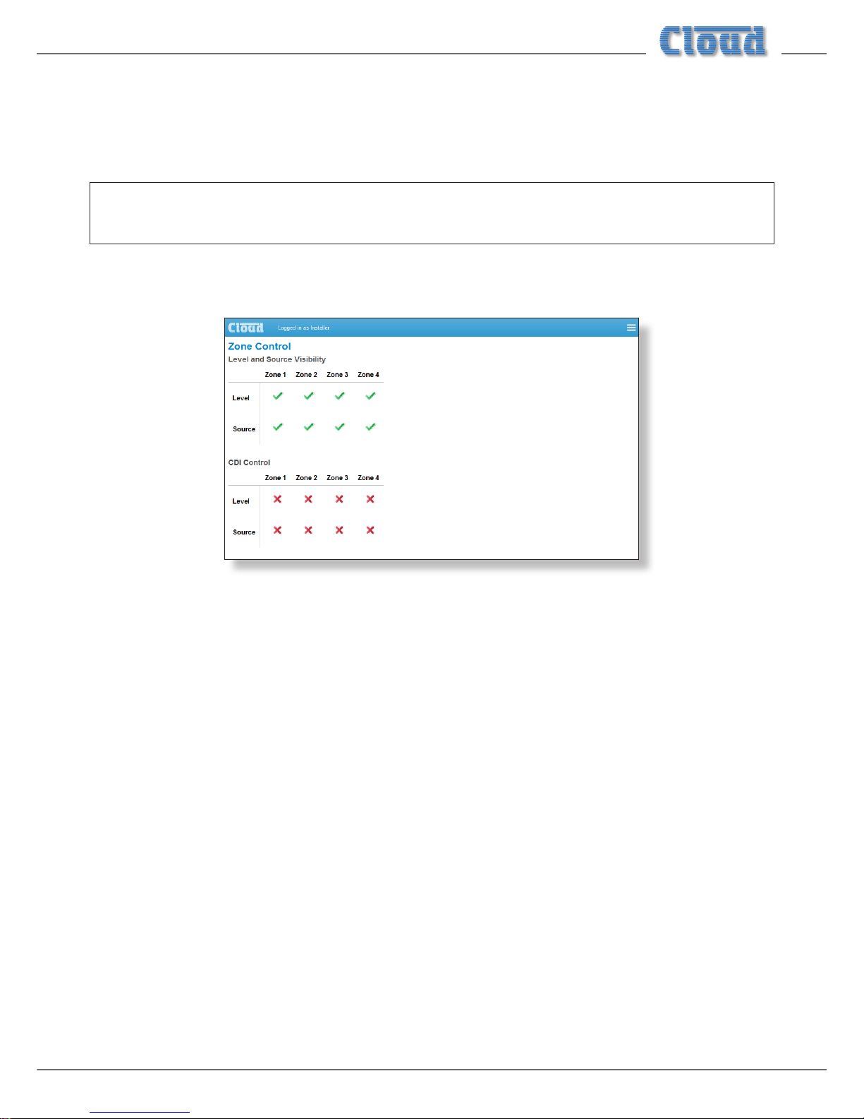
Zone Control
This page is divided into two sections consisting of similar matrixes: the upper matrix controls the content of the
Zone Settings pages, while the lower determines which music functions the CDI-46 controls on a per-zone basis.
Level and Source Visibility
The factory default for the appearance of the Zone Settings pages is as shown at “Zone Settings” on page 10. However, the
user may not wish music level, or music source selection, or either, to be available via a browser. By unticking Level or Source
for the Zone(s) in question, the controls will be removed from the page for that Zone. Note that it is also possible to dene
(globally) which zone functions each User has access to. See “User Security” on page 19 for more detais.
CDI Control
This matrix determines the 46-120 music functions over which the CDI-46 has control. The factory default is for no control at
all, and the installer should therefore enable the specic Zone/function combinations that require remote control from the card.
Note that this applies to all CDI-46 control options: serial control using RS-232 or Ethernet as well as control via a web browser.
This method allows for the option of using RL/RSL Series remote control plates in some Zones, and software control in others.
This matrix can be used to dene CDI-46 functionality on power-up. If the unit’s current settings are saved using the Default
option in Power-up Mode (see “System Defaults” on page 16), the CDI-46 will automatically resume control of those
control functions that have been assigned to the CDI-46, while those not thus assigned will continue to be controllable from
the front panel or remote control plates.
Page 14

CDI-46 Installation and Setup Guide V1.3
14
Labelling
The CDI-46 browser pages allow the Installer to name the line inputs, mic inputs, Zones and spot announcement messages
(when PM-SA Series paging microphones form part of the system). Names entered on the Labelling page will replace the
default names (Line 1, Mic 1, Group A, etc.) on all browser pages where they appear. This provides a much more intuitive
interface for the User.
The Labelling page is divided in four areas; the labels for the Line Inputs are at the top, scroll down to see the remainder:
Page 15

CDI-46 Installation and Setup Guide V1.3
15
Renaming is simply a matter of selecting the default name in the button(s) and entering the new name(s). Clicking an Upload
button (there are two, at the top and bottom of the page) will upload all the labels simultaneously; the names are loaded into
non-volatile memory on the CDI-46 card itself. The Refresh button reloads the Labelling page from the CDI-46 card, and
thus may be used to discard any changes that have been made to the labels on-screen since the last click of the Upload button.
Page 16
CDI-46 Installation and Setup Guide V1.3
16
System Defaults
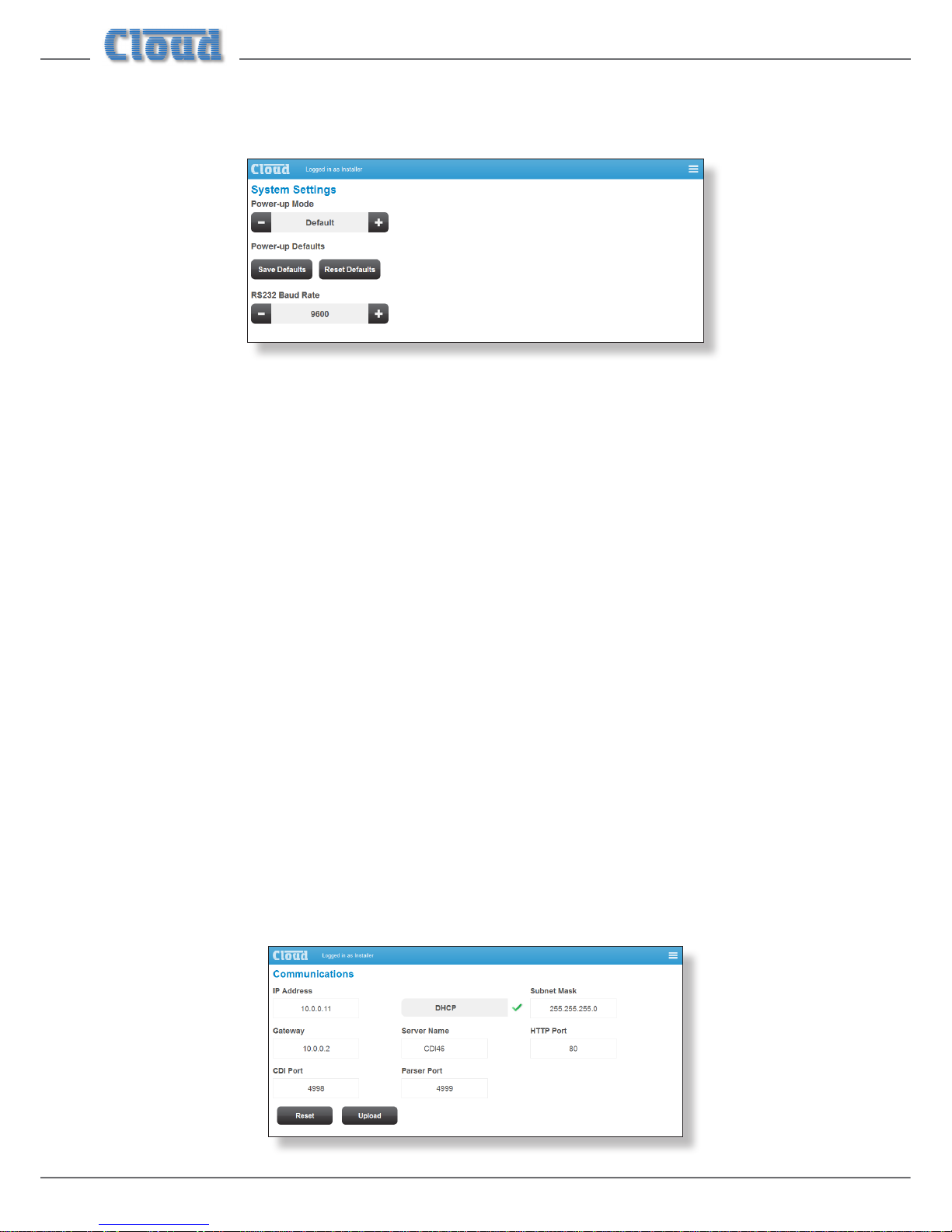
Click on System Defaults to open the System Settings page.
Power-up Mode and Power-up Defaults
It will often be desirable for the 46-120’s settings (input selections, levels, etc.), to be automatically restored to a known
state when the unit is re-powered after being off for a period (intentionally or otherwise). The Power-up Mode function
determines the state the 46-120/CDI-46 “wakes up” in when it is powered-up.
The Power-up Mode button selects the active Power Up option from the three available: Factory, Default and User.
With Factory set, the 46-120 will always return to its original factory settings on power-up. If Power-up Mode is set to
Default, the settings which have been saved in the Default memory (see below) are restored. The third option, User, will
restore the 46-120 to the settings they were in when the unit was last powered off.
Use the Save Defaults button to store the CDI-46’s current state in the Default memory. This will ensure that when the
46-120 is powered off and on again, it will resume the same state. This is particularly important when a mixture of hardware
control (front panel or remote plates) and browser control is being used in the various zones.
The Reset Defaults button may be clicked to restore the Default memory to the original factory settings. The original
settings disable music level and source control from the CDI-46 card in all zones; hardware control from the 46-120 front panel
or remote control plates remain operative. Reset Defaults will be most useful in resetting the CDI-46’s Default memory to a
known initial “off” state.
RS-232 Baud Rate
The default baud rate for the RS-232 serial port is 9600 baud. Use the + and – buttons to select an alternative if necessary. The
rates available are 4800, 9600, 19200, 38400, 57600 and 115200 baud. For all baud rates, the word structure uses 8 bits, one
stop bit and no parity.
Note that the RS-232 baud rate setting only applies to the RS-232 port, not to serial commands sent via Ethernet.
Network
Click on Network to open the Communications page.
Page 17

CDI-46 Installation and Setup Guide V1.3
17
This page displays the network settings for the currently selected CDI-46. The current IP Address, DHCP Status, Subnet
Mask, Gateway address and Server Name are conrmed. If DHCP is enabled, the values in IP Address, Subnet Mask
and Gateway are set automatically and the elds cannot be modied. If assigning these values (with DHCP disabled), ensure
that a suitable, reserved static IP address is used. This may require consultation with the network administrator.
Server Name – this eld has a default value of ‘CDI46’. In an installation where several 46-120s are installed, it will probably
be more helpful if each is given a more meaningful name – possibly relating to the zones each covers.
Click the Reset button to reset the page to the previous state if any changes have been made but not uploaded. Click the
Upload button to transfer any changes to the CDI-46.
HTTP Port, CDI Port and Parser Port: in the vast majority of installations, these network parameters will not need
adjustment. However, they are likely to become relevant if the CDI-46 is connected to an existing IT network. The correct
settings for these items will vary from one installation to another, and we recommend that the network administrator is
consulted as to the appropriate values.
HTTP Port – This is the virtual port that a browser will connect to. The default is universally “80”. It is sometimes changed for
rewalling or “security by obscurity” reasons. If this is the case, the value has to be specied in the browser URL with a colon,
e.g., http://cloud.co.uk:9000/ would be required if the HTTP port was set to 9000.
CDI Port – This is the TCP/IP port used by the CDI-46’s Ethernet to Serial Bridge functionality. See “Using the CDI-46 as an
Ethernet-to-serial bridge” on page 26 for more details.
Parser Port – This is the TCP/IP port used to receive serial control commands via Ethernet (instead of via RS-232)
Device Info
Click the Device Info tab to open the Device Information page.
This is an “Engineering” page which gives details of the versions of the various rmware elements in the CDI-46.
Page 18

CDI-46 Installation and Setup Guide V1.3
18
Firmware update
Download the CDI-46 rmware update from www.cloud.co.uk.
1. Read the update notes to check that the update is applicable to your unit.
2. Establish the Ethernet connection between the CDI-46 and your network switch. Launch your usual web browser and
connect to the CDI-46 in the usual way.
3. Log in using the Installer PIN.
4. Click Menu > Cong > Device Info.
5. Click Upload.
6. Enter the Installer PIN again.
7. The CDI-46 will now enter bootloader mode.
8. Close the browser page.
9. Run the Firmware Update application on a Windows® PC connected to the same network.
10. Click Discover.
11. Click the IP Address listed in BOLD font.
12. Check and conrm which settings you would like to overwrite on the Update interface.
13. Click Update.
14. Wait for the “Firmware updated successfully” message.
15. Click OK, then close the Firmware Update application
Change Installer PIN
Click the Change PIN tab to open the Reset your PIN page.
This page lets you change the Installer PIN. You will need to conrm the current PIN in the Enter your current PIN
eld before proceeding to enter a new one in both the Add a new PIN and the Conrm your new PIN elds, and Click
the Update button.
Page 19

CDI-46 Installation and Setup Guide V1.3
19
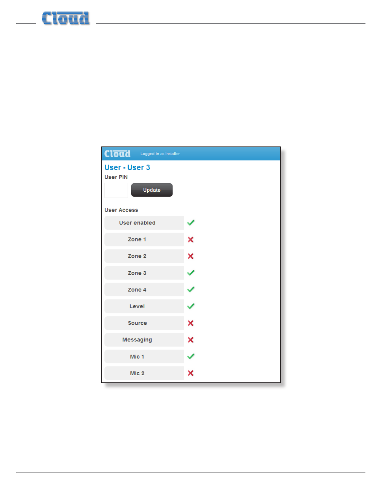
User Security
Click the User Security tab to reveal the list of Users:
The CDI-46 security system gives up to ten Users unique PIN access to the control pages. Additionally, a Guest User may access
the control pages without a PIN. Clicking on any of the ten User tabs opens the User privileges page for that User.
Page 20
CDI-46 Installation and Setup Guide V1.3
20
Note that only an Installer may dene Users and change their access privileges.
The exibility of the security system allows a client – if they wish - to give particular members of staff access only to certain
zones and control functions. Level control and/or source selection for each zone, plus permission to initiate PM-SA messages
and mic access may be dened individually for each user.
To dene User privileges, rst enter a PIN in the User PIN eld and click Update. User enabled must be selected (green
tick) for the set of functions listed below to take effect. Select the zones for which the User should have access, and select
Level and/or Source according to requirements. If the User should be able to initiate announcements from a PM-SA paging
mic, select Messaging. If the User should have the authority to enable microphones in his/her allocated Zones, select Mic 1
and/or Mic 2 as appropriate.
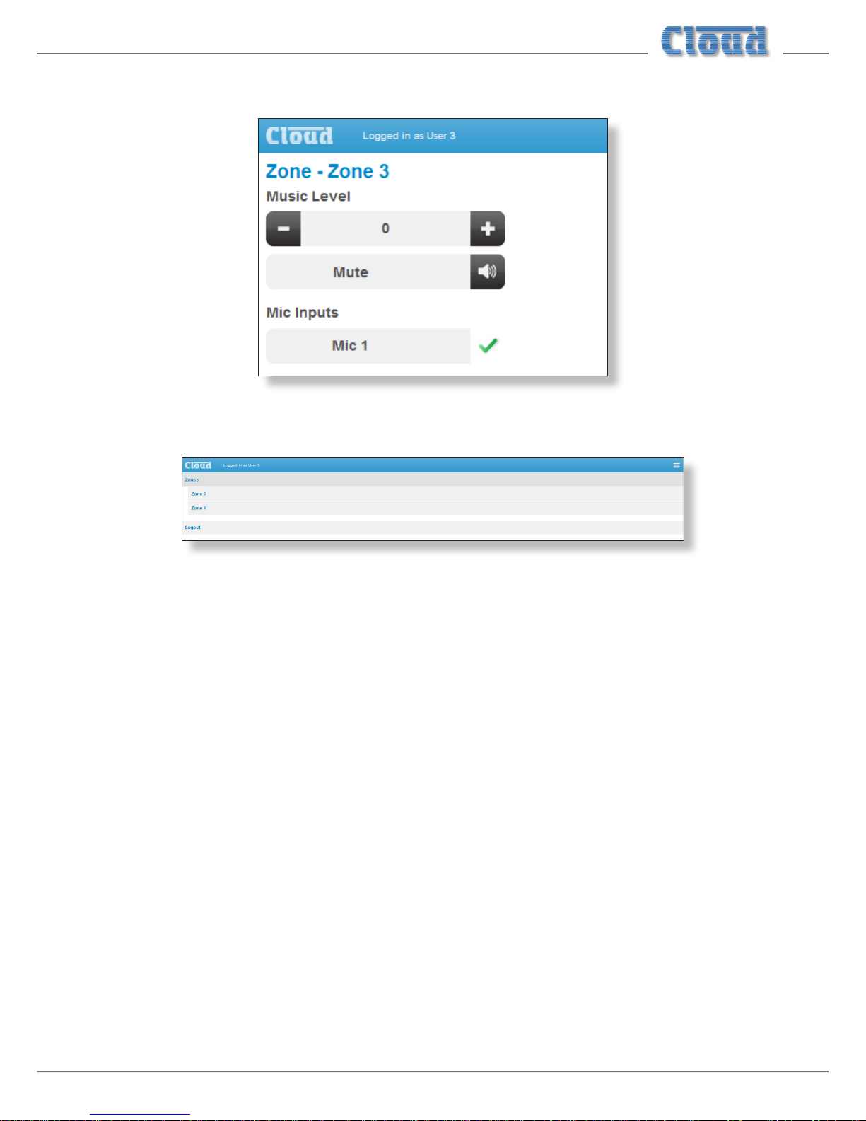
Once User privileges have been dened, the User(s) may log on using their own PINs, and will be presented with page layouts
containing only those functions which their access privileges allow. An example is shown below, where User 3 has been given
access only to Zones 3 and 4 and can adjust level but not select music sources. Messaging is disabled (which should always be
the case if the system does not include a PM-SA paging mic), but the User can enable Mic Input 1 if required.
Page 21
CDI-46 Installation and Setup Guide V1.3
21
This will give User 3 the control page shown below:
User 3’s main menu will look as below – note that Zones 1 and 2 are no longer available.
Guest User
The security system provides for one additional User – the Guest User.
If User enabled is active for the Guest User, it is possible to browse to the web interface pages without a PIN being
requested. However, as with any other User, only those functions that have been assigned by an Installer will be available. The
Guest User has been included to allow casual access to unit functionality without a PIN logon. For many installations, this may
raise security issues, hence it is disabled by default.
Page 22
CDI-46 Installation and Setup Guide V1.3
22
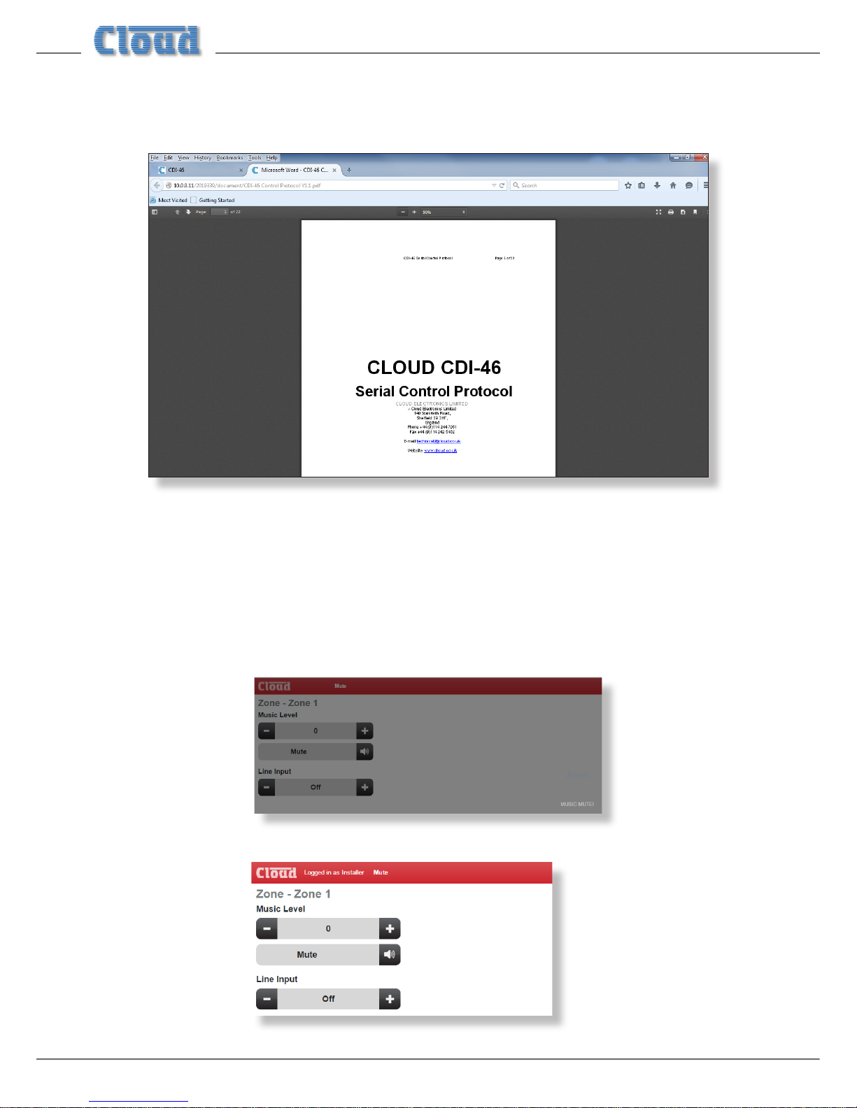
Documents
Selecting Documents, then Control Protocol opens a new browser tab, displaying a PDF version of the CDI-46’s Serial
Control Protocol.
This is a comprehensive document containing full details of all aspects of the CDI-46’s serial control protocol. See also “Abridged
command set” on page 24.
Music Mute
The browser interface also provides indication of Music Mute status. The nature of the indication depends on whether you are
logged in as a User or an Installer.
When an external mute command is applied to the 46-120’s Music Mute port, the browser interface becomes unavailable to a
User while the mute is active. The current page is greyed-out and the page heading banner changes from blue to red:
If you are logged in as an Installer, control remains available, but the page heading banner changes colour to red, with the word
Mute displayed:
Page 23

CDI-46 Installation and Setup Guide V1.3
23
46-120 Serial Control
The CDI-46 is equipped with a bi-directional RS-232 serial interface.
As a receiver, the interface permits external control of almost every 46-120 function, parameter and setting. The CDI-46
appears as a DCE (Data Communications Equipment) device to controlling equipment. As the controlling device will probably
be congured as a DTE device, this requires the use of a straight (uncrossed) cable with the Tx (Data Transmit) pins at the cable
ends connected to each other and the Rx pins (Data Receive) similarly connected to each other.
Pinout
The rear panel RS232 connector is a 3-pin, 3.5 mm-pitch screw-terminal connector. The pinout is shown in the table:
PIN LABEL FUNCTION
1 Gd Ground
2 Rx Data transmit
3 Tx Data receive
Note that not all control systems interpret “Tx” and “Rx” the same way, and the installer should check whether pins 2 and 3
should be “crossed” within the cable.
Port parameters:
PARAMETER VALUE/SETTING
Data Type RS-232 serial
Data Speed 4800/9600/19200/38400/57600/115200 baud, software-selectable
Word Length 8 bits
Parity None
Stop Bits One
The CDI-46 is additionally able to receive the same serial commands in the form of TCP/IP data via the
ETHERNET INTERFACE connector.
The full RS-232 protocol is beyond the scope of this manual, but is available to view in your browser (see “Documents” on
page 22), or can be downloaded from www.cloud.co.uk.
Page 24

CDI-46 Installation and Setup Guide V1.3
24
Abridged command set
The commands listed in the table below are some of those most commonly required when controlling a 46-120 from an
AV control system. For all other commands, data requests and responses, please refer to the CDI-46’s full RS-232 protocol
document.
GENERAL FORMAT
FUNCTION COMMAND (ASCII)
Route Line Input x to Zone y
<Zy.MU,Sx/>
Set music level in Zone y to –m dB
<Zy.MU,Lm/>
Reduce music level in Zone y by p dB
<Zy.MU,LDp/>
Increase music level in Zone y by q dB
<Zy.MU,LUq/>
Enable Mic x
<Mx,O/>
Mute Mic x
<Mx,M/>
Enable paging to Zone y (see Example 4)
<PM,PAy/>
Release paging
<PM,PR/>
Activate PM-SA message stored in Group n
<EX,SAn/>
Examples
1. Input Selection
The values of x and y in the general format are the Line Input No. (1 to 6) and the Zone No. (1 to 4) respectively.
EXAMPLE COMMAND (ASCII) COMMAND (HEX)
Select Input 3 in Zone 2
<Z2.MU,S3/>
3C 5A 32 2E 4D 55 2C 53 33 2F 3E
2. Zone Levels
Levels can either be set to an absolute value (in dBs), or increased/decreased by a specied number of dBs. Either may be
dened in steps of 1 dB.
For absolute levels, the number of dBs corresponds to attenuation rather than gain, thus 0 dB is maximum level and at -90
dB the zone is muted. The values of y in the general format is the Zone No. (1 to 4) and m is the attenuation level in one-dB
steps (0 to 90) respectively.
To alter the Zone level by a specied amount, the additional ASCII characters ‘U’ (up) or ‘D’ (down) are added to the string.
The values of y, p and q in the general format are the Zone No. (1 to 4), the level increase in one-dB steps (0 to 90), or the
level decrease in one-dB steps (0 to 90) respectively. A command to increment the level by a number of dBs greater than
the current attenuation will set the level to maximum. Similarly, a command that would decrement the level below 90 dB
attenuation will mute the Zone output.
EXAMPLE COMMAND (ASCII) COMMAND (HEX)
Set level in Zone 2 to -12 dB
<Z2.MU,L12/>
3C 5A 32 2E 4D 55 2C 4C 31 32 2F 3E
Reduce level in Zone 1 by 10 dB
<Z1.MU,LD10/>
3C 5A 31 2E 4D 55 2C 4C 44 31 30 2F 3E
Increase level in Zone 4 by 6 dB
<Z5.MU,LU6/>
3C 5A 34 2E 4D 55 2C 4C 55 36 2F 3E
Page 25

CDI-46 Installation and Setup Guide V1.3
25
3. Enable/Disable Mics
Either of the 46-120’s two mic inputs may be enabled or disabled. This may be done globally (for all zones), on a per-zone
basis. The value of x in the general format is the Mic input (1 or 2).
EXAMPLE COMMAND (ASCII) COMMAND (HEX)
Enable Mic 1 globally
<M1,O/>
3C 4D 31 2C 4F 2F 3E
Disable Mic 2 globally
<M2,M/>
3C 4D 32 2C 4D 2F 3E
Enable Mic 1 for Zone 2 only
<Z2.M1,O/>
3C 5A 32 2E 4D 31 2C 4F 2F 3E
4. Enable/Release Paging
RS-232 control of paging allows an audio signal connected at MIC 1 to be routed for paging.
This command differs from the others in that the value of y in the general format is in the form of a 4-character mask of ASCII
“X’s” (select) and “O’s” (don’t select), with the character position in the mask denoting the Zone number.
EXAMPLE COMMAND (ASCII) COMMAND (HEX)
Enable paging to Zone 3
<PM,PAOOXO/>
3C 50 4D 2C 50 41 4F 4F 58 (4F) 2F 3E
Enable paging to Zones 1 and 4
<PM,PAXOOX/>
3C 50 4D 2C 50 41 4F 4F 4F 58 2F 3E
Cancel paging
<PM,PR/>
3C 50 4D 2C 50 52 2F 3E
Note that it is not strictly necessary to transmit the “O” character (4Fh) for channel numbers above the highest being paged.
Thus <PM,PAOOX/> (ASCII) would sufce in the rst example above. However, the full four characters are shown in the table
for completeness, with the extra characters in brackets in the hex version.
Page 26

CDI-46 Installation and Setup Guide V1.3
26
Using the CDI-46 as an Ethernet-to-serial bridge
The CDI-46 may be used as an Ethernet-to-serial bridge. Many AV control systems now transmit serial data strings in TCP/IP
format via an Ethernet interface, rather than from an RS-232 port. However, some equipment – projectors and other display
devices, for example – only accept serial control via an RS-232 port.
The CDI-46 is able to receive serial data at the Ethernet port and re-transmit it from the RS-232 port, and thus act as an
Ethernet-to-serial converter or bridge.
46-120
RS-232
Serial Port
Ethernet
This function uses the CDI-46’s virtual CDI port, whose address has the default value of 4998. If the controlling device is only
able to support remote ports in a certain address range (i.e., not including 4998), the port address can be changed on the
Communications page of the browser interface (accessed from Cong > Network).
Cable lengths
RS-232 serial communication can use either shielded or unshielded cable. The longest cable run that can be practically used for
error-free operation in a given installation will depend on several factors: cable type, the baud rate used and the amount and
type of electrical noise present in the cable’s vicinity.
A realistic gure for maximum cable length is 250 ft. (76 m) using good-quality shielded cable and 100 ft. (30 m) using unshielded
cable, at 9600 baud (the most common data rate).
However, the gure may be higher or lower in a particular installation. Lowering the baud rate will permit signicantly longer
cable runs to be used.
Page 27

CDI-46 Installation and Setup Guide V1.3
27
Page 28

www.cloud.co.uk www.cloudusa.pro
 Loading...