

Page 1
BT-1 Installation Guide v1.0
1
BT-1 Series Bluetooth Wireless
Audio Module
Installation Guide
BT-1FW (UK, White)
BT-1FB (UK, Black)
BT-1EW (UK, White)
BT-1EB (UK, Black)
BT-1
PUSH
STATUS
- -
TO PAIR
2s 5s
BT-1
PUSH
STATUS
- -
TO PAIR
2s 5s
BT-1AFW (USA, White)
BT-1AEW (USA, White)
Page 2

BT-1 Installation Guide v1.0
2
Conformities
The BT-1 is compliant with the following EMC directives:
EN 301 489-17 V2.1.1
EN 300 328 V1.8.1
EN60950-1:2006+A11:2009+A1:2010+A12:2011
Page 3

BT-1 Installation Guide v1.0
3
Contents
Conformities ................................................................................................................................... 2
Introduction .................................................................................................................................... 4
BT-1 variants ................................................................................................................................................................... 4
Mounting - mechanical .................................................................................................................. 4
Faceplate Controls ......................................................................................................................... 5
Block Diagrams .............................................................................................................................. 6
Installation - connections .............................................................................................................. 7
Connection to a Facility Port (BT-1F only) .............................................................................................................. 7
Connecting to an Extension Port (BT-1E only) ....................................................................................................... 9
Connecting a BT-1F to an LM-2................................................................................................................................10
Connecting a BT-1E to an LE-1 or BE-1 .................................................................................................................10
Connecting an RL/RSL plate to a BT-1F..................................................................................................................11
Set-up Options ............................................................................................................................. 12
Secured and non-secured modes ............................................................................................................................. 12
RF power setting .......................................................................................................................................................... 13
Bluetooth ident ............................................................................................................................................................ 14
Operation ...................................................................................................................................... 14
Power considerations ................................................................................................................... 15
Page 4

BT-1 Installation Guide v1.0
4
Introduction
The BT-1 is a wireless remote audio input module for use with all Cloud products tted with an RJ45 Facility Port or an RJ45
Extension Port.
The BT-1 enables compatible portable devices such as laptops, tablets and smartphones to stream audio wirelessly to the
interface, and thus into the audio system of the Zone where the interface is installed.
The BT-1 is connected to the host unit’s Facility Port or Extension Port by a single Cat 5 cable. Alternatively, it may be connected
to remote Cloud input modules such as the LM-2, LE-1 and BE-1 in “daisy-chain” fashion, these modules being connected in
turn to the host unit. Screened Cat 5 cable and shielded RJ45 connectors should be used in all cases. If the Zone where the
BT-1 is installed also requires RL and RSL Series remote control plates, they may be “daisy-chained” to the BT-1 instead of being
connected to the host unit, which will simplify installation wiring in many cases.
BT-1 variants
There are two primary variants of the BT-1: the BT-1F, suitable for use with host units tted with one or more Facility Ports, and
the BT-1E, suitable for use with host units tted with one or more Extension Ports. The BT-1F will route an (L+R) mono sum of
the streamed audio to the host unit; the BT-1E routes the audio in stereo.
Variant BT-1F may be used with the following Cloud products, which are tted with Facility Port(s):
• Z4MK4 and Z8MK4 Zone Mixers
• Z4MK3 and Z8MK3 Zone Mixers
• 46-120 and 46-120MEDIA Zone Mixing Ampliers
• MA40F, MA40T and MA40E Mini Ampliers
Variant BT-1E may be used with the following Cloud products, which are tted with Extension Port(s):
• DCM1 Digital Control Zone Mixer
• DCM1e Ethernet Digital Control Zone Mixer
BT-1E and BT-1F variants may be distinguished physically by an ident on the rear PCB: a black mark will be visible in one of two
checkboxes:
• DCM1: BT-1E
• FACILITY: BT-1F
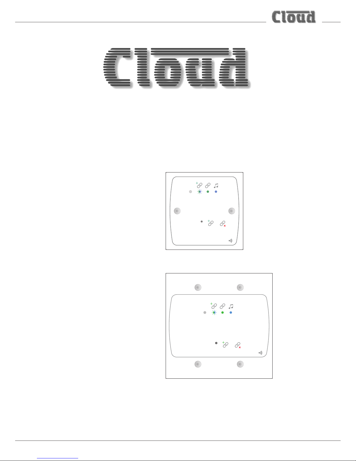
Additionally, the BT-1 is available in two form factors to suit either UK single-gang or US standard dual-gang electrical back
boxes; US-size modules are denoted by a sufx ‘A’ to the Part No.
UK-size modules are available either in white (a further sufx ‘W’ to the Part No.), or black (sufx ‘B’) nish.
NOTE: Unless specically stated otherwise, all references to “BT-1” in this Installation Guide can be taken to apply to all BT-1
mechanical and cosmetic variants.
Mounting - mechanical
BT-1 (UK version)
The Cloud BT-1 (BT-1FB, BT-1FW, BT-1EB, BT-1EW) ts a standard UK-style single-gang electrical back box. The box used should
have a depth of at least 35 mm.
BT-1A (US version)
The Cloud BT-1A (BT-1AFW, BT-1AEW) ts a standard US dual-gang electrical ‘J’ box in vertical orientation. The box used
should have a depth of at least 1½”.
Page 5
BT-1 Installation Guide v1.0
5
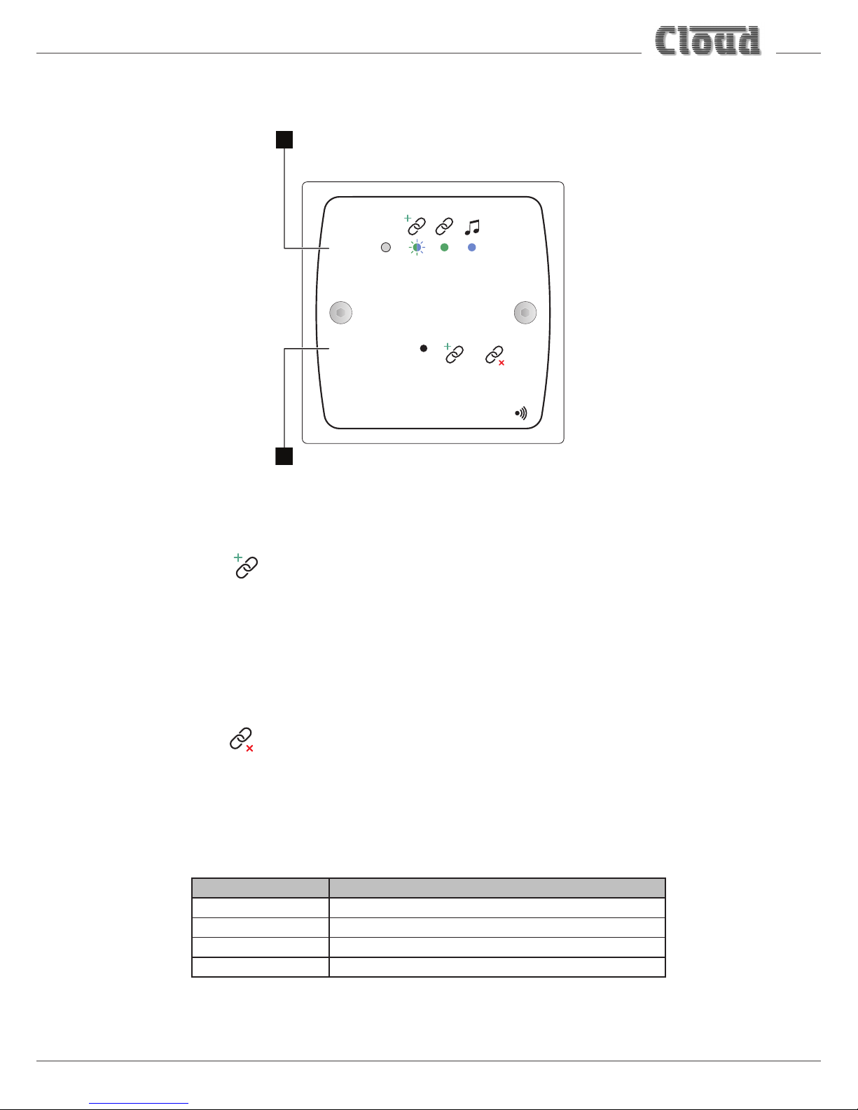
Faceplate Controls
UK version illustrated
BT-1
PUSH
STATUS
--
TO PAIR
2s 5s
2
1
1. PUSH-TO-PAIR – recessed push-button accessed through a 2 mm dia. hole. The two “chain” symbols adjacent to the
access hole depict the effect of “short” and “long” presses on the button:
Short press:
2s
Pressing the button for 2 secs puts the BT-1 into “Awaiting Pairing” mode. The BT-1 will be visible on the scan list of
external wireless devices within range for 30 seconds; during this timeout period, an external device may initiate pairing.
Once paired, no other device can connect to the BT-1. The STATUS LED [2] blinks blue/green in Awaiting Pairing mode.
If no device connects during the timeout period, the BT-1 reverts to “Secure” mode, preventing a connection to be made
by new devices.
Long press:
5s
Pressing the button for 5 secs puts the BT-1 into “Factory” mode. This clears any active connection and the BT-1 will not be
visible on any external devices’ scan lists (unless the BT-1 is in Unsecured mode – see “Secured and non-secured modes”
on page 12. The STATUS LED [2] will turn off.
2. STATUS – bicolour (green/blue) LED indicating BT-1 operating mode:
LED STATE MEANING
Off BT-1 is not connected to any external device
Flashing blue/green BT-1 is awaiting pairing
Green BT-1 is connected to an external device
Blue Audio data is being streamed from the external device
Page 6

BT-1 Installation Guide v1.0
6
Block Diagrams
BT-1F
BT-1E
Page 7

BT-1 Installation Guide v1.0
7
Installation - connections
Connection to a Facility Port (BT-1F only)
The BT-1 has two PCBs “piggy-backed” onto the rear of the faceplate. The RJ45 output connector (SK1) is located on the upper
PCB:
LOCATION OF REAR RJ45 CONNECTOR
(Sketch simplified; only primary components shown)
RJ45 OUTPUT
CONNECTOR
INSERT PLUG THIS
WAY, LATCH UPWARDS
SK1
RSL-6
3 2 1
The output connector should be connected to the host unit’s FACILITY PORT for the Zone in which it is installed* with
screened Cat 5 cable and shielded RJ45 plugs.
Connect to SK1
Screened
Cat 5 cable
HOST UNIT (Z8MK4 illustrated)
100 m max
Connect to
FACILITY PORT
BT-1(UK version illustrated)
The maximum total Cat 5 cable length should not exceed 100 m. If further modules are being “linked” together (see “Connecting
a BT-1F to an LM-2” on page 10), this gure applies to the overall cable run from the host unit to the farthest module in the
chain.
Page 8

BT-1 Installation Guide v1.0
8
IMPORTANT: Because the cables carry low-level audio, only screened Cat 5 should be used, the foil screen of the cable being
bonded to the metal screening can of the plugs. If a BT-1 is being installed in very close proximity to the host unit, it may be
possible to use ready-made screened Cat 5 “patch” cables of short length. In all other situations, shielded RJ45 plugs should be
crimped onto the installed screened Cat 5 cable using the pinout shown below.
PIN USE Cat 5 CORE
1 Audio ‘cold’ phase (-) White + Orange
2 Audio ‘hot’ phase (+) Orange
3 Priority VCA control White + Green
4 + Vsupply Blue
5 0 V White + Blue
6 - Vsupply Green
7 Music level control (0 to 10 V) White + Brown
8 Music source select control (0 to 10 V) Brown
SCN GND ref for system music controls Connector shell
The audio streamed to the BT-1F module will be available in the Zone as soon as the module is connected to the host unit’s
Facility Port for that Zone. Audio fed into the Zone will be an (L+R) mono sum of the stereo audio streamed from the user’s
wireless device (e.g., smartphone, tablet, etc.). Audio volume will be controlled solely from the user’s device in the normal way
and will be unaffected by any of the host unit’s front panel controls.
* There is no reason why the module cannot be connected to the Facility Port of a Zone other than that in which it is installed – though this is unlikely to be
an common installation scenario.
Page 9

BT-1 Installation Guide v1.0
9
Connecting to an Extension Port (BT-1E only)
The BT-1E is connected in exactly the same manner as the BT-1F, except that it should be connected to an EXTENSION
PORT on the host unit.
Connect to SK1
Screened
Cat 5 cable
HOST UNIT (DCM1 illustrated)
100 m max
Connect to
EXTENSION PORT
BT-1(UK version illustrated)
IMPORTANT: Note that on the DCM1 and DCM1e Digital Control Zone Mixers, the four Extension Ports are alternative
input connectors for Line Inputs 1 to 4. When a BT-1E is connected to an Extension Port, the corresponding pair of Line Input
phono connectors must not be connected to a music source device of any kind.
The maximum total Cat 5 cable length should not exceed 100 m. If further modules are being “linked” together (see “Connecting
a BT-1E to an LE-1 or BE-1” on page 10), this gure applies to the overall cable run from the host unit to the “furthest”
module in the chain.
IMPORTANT: Because the cables carry low-level audio, only screened Cat 5 should be used, the foil screen of the cable being
bonded to the metal screening can of the plugs. If a BT-1 is being installed in very close proximity to the host unit, it may be
possible to use ready-made screened Cat 5 “patch” cables of short length. In all other situations, shielded RJ45 plugs should be
crimped onto the installed screened Cat 5 cable using the pinout shown below:
PIN USE Cat 5 CORE
1 Left audio channel ‘cold’ phase (-) White + Orange
2 Left audio channel ‘hot’ phase (+) Orange
3 Model sense White + Green
4 - Vsupply Blue
5 0 V White + Blue
6 - Vsupply Green
7 Right audio channel ‘hot’ phase (+) White + Brown
8 Right audio channel ‘cold’ phase (-) Brown
SCN GND ref for system music controls Connector shell
On the DCM1 and DCM1e, the RJ45 Extension Ports are alternative input connectors for Line Inputs 1 to 4, and are NOT
associated exclusively with any of the eight Zones which the host unit supports. Use the Select Input option in the Music Menu
to assign the Line Input to which the BT-1 is connected to route the streamed audio to the Zone required. See page 28 of the
DCM1/DCM1e Installation and User Guide for full details.
Page 10

BT-1 Installation Guide v1.0
10
Connecting a BT-1F to an LM-2
If a BT-1F is being installed in a Zone which also contains an LM-2 Remote Input/Control Module, it should be connected to the
LM-2’s LINK connector instead of directly to the host unit, as shown below:
OUTPUT
LINK
Connect to
OUTPUT socket
Screened Cat 5
cable
HOST UNIT
(Z4 / Z8
MK4 OR 46/120 / 46/120MEDIA)
100 m max
Connect to
FACILITY PORT
Connect to
Output socket
Connect to
LINK socket
Screened Cat 5
cable
LM-2
BT-1F
If multiple LM-2s are “daisy-chained” in the Zone, the BT-1F should be connected to the LINK connector of the “last” LM-2 in
the chain. Note that as the BT-1F has no Link connector, it must always be the last module in a chain.
For details of how to congure a Facility Port to operate correctly with an LM-2 Remote Input/Control Module, please see the
LM-2 Installation Guide.
Connecting a BT-1E to an LE-1 or BE-1
If a BT-1E is being installed in a Zone which also contains an LE-1 or BE-1 Remote Input Module, it should be connected to the
LINK connector on the Remote Input Module instead of directly to the host unit, as shown below:
Connect to
OUTPUT socket
Screened Cat 5
cable
HOST UNIT
(DCM1/DCM1e)
100 m max
Connect to
EXTENSION PORT
Connect to
Output socket
Connect to
LINK socket
Screened Cat 5
cable
BT-1E
LE-1
OUTPUT
LINK
LE-1 shown in example
If multiple LE-1/BE-1s are “daisy-chained” to an Extension Port, the BT-1E should be connected to the LINK connector of the
“last” LE-1/BE-1 in the chain. Note that as the BT-1E has no Link connector, it must always be the last module in a chain.
Note that it is not possible to connect a BT-1E to an ME-1 Microphone Input Module; ME-1 modules are connected to a DCM1’s
Microphone Inputs, not the Extension Ports.
Page 11

BT-1 Installation Guide v1.0
11
Connecting an RL/RSL plate to a BT-1F
The BT-1F is provided with a 3-pin screw-terminal connector (on the rear PCB) to permit the connection of an RL-1 or RSL-6
remote control plate. These plates normally connect to the Music Control Port for the relevant Zone at the host unit, but it
may simplify wiring to connect one to the BT-1.
123
RL-1
SINGLE-CORE SCREENED CABLE MAY BE USED
SK1
BT-1F
RSL-6
3 2 1
SK1
1 2 3
REMOTE SOURCE & LEVEL CONTROL WIRING
RSL-6
USE TWO-CORE SCREENED CABLE
BT-1F
RSL-6
3 2 1
An RL-1/RSL-6 connected to a host unit via a BT-1F in this manner will only operate correctly if the host’s Music Control
functions have been correctly congured. For details of how to do this, please see the Installation Guide for the host unit.
Page 12

BT-1 Installation Guide v1.0
12
Set-up Options
Setting up the BT-1 is very simple: there are two 4-way DIP switches on the lower rear PCB which may need to be set to
congure the BT-1 to suit the specics of the installation.
(Sketch simplified; only primary components shown,
BT-1F shown as example)
SK1
1 432
ON
SECURE/
NON-SECURE
MODE
RF POWER
LEVEL
1 432
ON
BLUETOOTH
IDENT
RSL-6
3 2 1
DIP switches shown with factory default settings
Secured and non-secured modes
Normal operation of the BT-1 will be with “Secured” mode selected: this requires the user to press the PUSH-TO-PAIR
button to place the module into “Awaiting Pairing” mode, and then to initiate pairing from his/her portable wireless device
within 30 seconds.
Under some circumstances, it might be preferable to select “Non-secured” mode to circumvent use of the PUSH-TO-PAIR
button, giving any user within range the ability to connect to the BT-1.
“Secured” mode is selected by setting SW1 of the left-hand DIP switch (as seen from the rear of the BT-1) to ON (switch
down). With SW1 OFF, the BT-1 is in “Non-secured” mode.
Page 13

BT-1 Installation Guide v1.0
13
RF power setting
The RF power level at which the Bluetooth interface operates – and hence the operational range of the BT-1 – is adjustable.
Units are shipped with the power setting at maximum, but in some installation circumstances, it may be desirable to limit the
power of the module, thereby restricting the operational range. Typically, it may be necessary to do this where there are BT-1
modules installed in adjoining rooms, as it reduces the likelihood of the BT-1 in one room appearing in the Device List on
smartphones, tablets, etc., in other rooms.
The power level is set by SW2, SW3 and SW4 on the left-hand DIP switch (as seen from the rear of the module). The three
switches work in a binary manner, thus eight power levels are theoretically available, though this is limited to seven in practice.
The power levels are in 4 dBm steps. The table below lists the available power settings:
LEVEL SW2 SW3 SW4 POWER
1
1 OFF OFF OFF -18 dBm
2 OFF OFF ON -14 dBm
3 OFF ON OFF -10 dBm
4 OFF ON ON -6 dBm
5 ON OFF OFF -2 dBm
6 ON OFF ON +2 dBm
7 ON ON OFF
+6 dBm
8
2
ON ON ON
NOTES:
1. relative to 0 dBm = 1 mW
2. Level 8 is set at the factory as the default
Page 14

BT-1 Installation Guide v1.0
14
Bluetooth ident
In installations where multiple BT-1s are installed, it will generally be desirable to give each a unique identier. The right-hand
DIP switch (viewed from the rear) allows one of 16 idents to be assigned to each BT-1.
The BT-1 appears in the Device List on a user’s laptop, tablet, etc., with a numeric sufx (#01 to #16) to indicate all the BT-1s
that are within range; in this way, the user can be certain of connecting to the intended module. It is recommended that installers
afx a printed label to each module to indicate the ident set, in such cases.
The idents are selected by the four sections of the DIP switch using binary weighting, as shown below:
IDENT SW1 SW2 SW3 SW4
#1 OFF OFF OFF OFF
#2 OFF OFF OFF ON
#3 OFF OFF ON OFF
#4 OFF OFF ON ON
#5 OFF ON OFF OFF
#6 OFF ON OFF ON
#7 OFF ON ON OFF
#8 OFF ON ON ON
#9 ON OFF OFF OFF
#10 ON OFF OFF ON
#11 ON OFF ON OFF
#12 ON OFF ON ON
#13 ON ON OFF OFF
#14 ON ON OFF ON
#15 ON ON ON OFF
#16 ON ON ON ON
Operation
When the BT-1 rst has power applied to it, the STATUS LED ashes alternate green/blue for a few seconds to conrm
correct operation.
Normal (“Secured”) mode:
In Secured Mode, the module will appear in the Bluetooth Device List of any smartphone, tablet, etc. within range. At this
time, no connection will be in place, and it will not be possible to pair with the BT-1.
To initiate pairing, press the PUSH-TO-PAIR button for two seconds; the STATUS LED will ash alternate blue/green
for 30 seconds, indicating “Awaiting Pair” mode. During this timeout period, a user can select the BT-1 from his/her Device
List, and if pairing is successful, the STATUS LED will turn steady green. The BT-1’s ident will now not be visible on other
Device Lists, and therefore it will not be possible for any other device to connect to it. In order for another device to
connect to the BT-1, the current device must rst disconnect.
Streaming may now commence: on receipt of audio data, the STATUS LED turns blue.
Disconnection may be achieved in three ways:
• from the user device – the connection is cancelled and the STATUS LED goes out. The BT-1’s internal “User List”
will retain the identity of the user’s device, in which case, that specic user will be able to reconnect at a future time
without the PUSH-TO-PAIR button being pressed.
• from the BT-1 itself, by pressing the PUSH-TO-PAIR button for two seconds. This has exactly the same
consequences as cancelling the connection from the user device.
• From the BT-1, by pressing the PUSH-TO-PAIR button for ve seconds. This places the BT-1 in “Factory” mode
and clears the internal “User List”. Any device that was previously connected to the BT-1 will need to reconnect
with the use of the PUSH-TO-PAIR button as described above.
Page 15

BT-1 Installation Guide v1.0
15
Non-secured mode:
In Non-secured mode, it is not necessary to initiate a connection with the PUSH-TO-PAIR button. The BT-1 will “pair”
with the rst device that requests pairing. Once pairing is established, no other device can connect to it, in the same way
as in Secured mode.
Streaming may now commence: on receipt of audio data, the STATUS LED turns blue.
Disconnection may be achieved by any of the three methods outlined above for “Secured” mode.
Power considerations
The BT-1 will operate from a DC power supply in the range 12 V to 24 V. This will be supplied by the host unit’s Facility Port
or Extension Port via the Cat 5 connection: Cloud Z4/Z8MK3 host units supply +/- 15 V from their Facility Ports while the
Z4/Z8MK4 and 46-120 host units supply +/-12 V. The DCM1 range supply +/- 12 V from their Extension Ports.
The BT-1 consumes 20 to 26 mA from the host unit’s power supply. In the majority of installations, the host unit will have ample
spare current capacity to power one or more BT-1s. However, installers should note that this may not be the case in a very large
system with multiple remote modules in several Zones. If there is any doubt about the power capability, please refer to the host
unit’s Installation and User Guide where full details of power supply ratings can be found.
Should you have any questions concerning the installation and connection of the Cloud BT-1, please visit
www.cloud.co.uk/resources, where you will nd additional technical information.
Page 16

www.cloud.co.uk www.cloudusa.pro
 Loading...