

Page 1

Bose Two Channel
Equalisation Module
Installation Guide
V2.0
Cloud Electronics Limited
140 Staniforth Road, Sheffield, S9 3HF England
Tel +44 (0) 114 244 7051
Fax +44 (0) 114 242 5462
E-mail
Web site http://www.cloud.co.uk
info@cloud.co.uk
Page 2
1 Bose Two Channel Equalisation Module: Installation Guide
Bose Two Channel Equalisation Module
Installation Guide
1 Models
This Bose equalisation module is compatible with the CX-A4 and CX-A6
multi-channel amplifiers, and is available in two models:
•
Model 8 card for use with Bose
•
Model 32 card for use with Bose
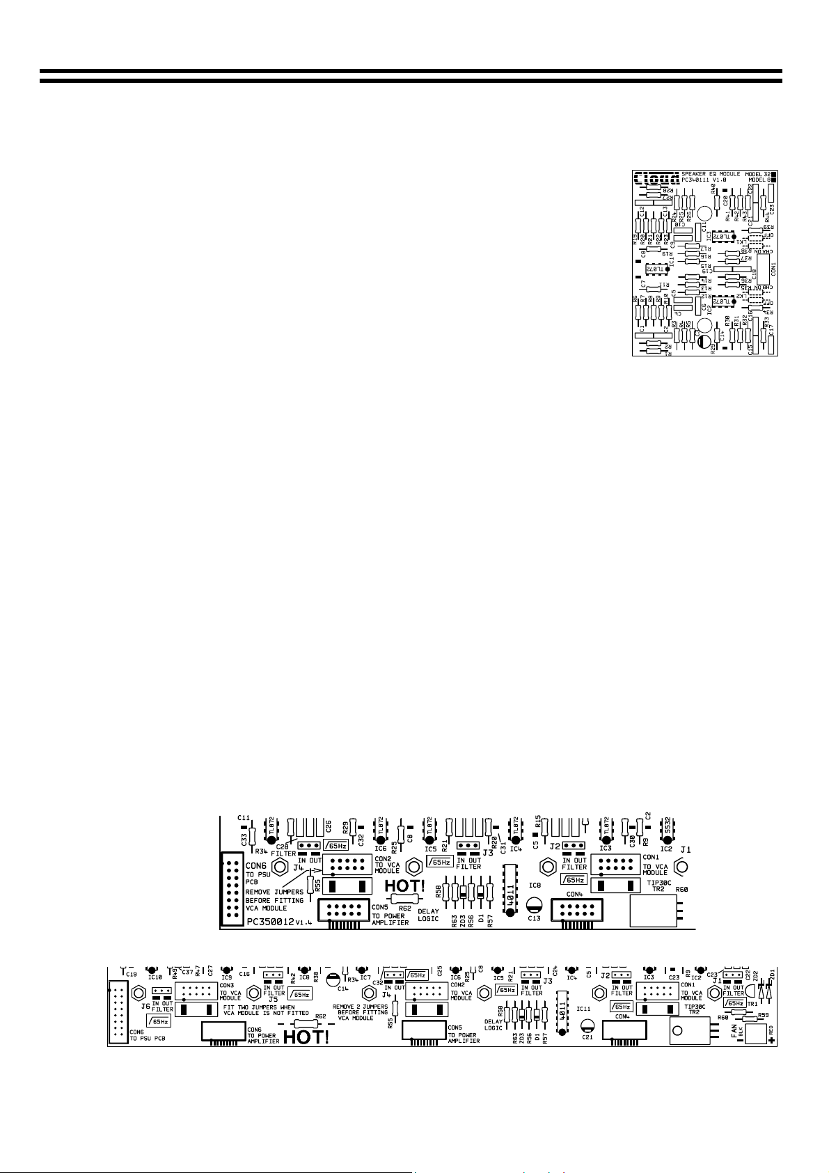
Each channel of the Bose equalisation module can be turned on or off at
the installers discretion by moving the following links to their ON or OFF
positions. Link 1 and 2 can be found adjacent to the connector marked as
CON1 on the Bose
equalisation module PCB.
LK1 controls Channel A
LK2 controls Channel B
2 Installation Information
The Bose equalisation module cannot be installed to a channel that has a VCA module fitted.
Connectors for the Bose equalisation modules are located approximately 50mm from the rear of
the unit. They are clearly marked as ‘CON1’, ‘CON2’ and ‘CON3’:
CON 1 = Channel 1&2
CON 2 = Channel 3&4
CON 3 = Channel 5&6 (only on CX-A6)
Compatible Bose
65Hz high pass filters switched ‘on’ by moving the relevant jumper to the ‘IN‘ position. The
jumpers are clearly marked as J1-6:
J1
= Channel 1,
* = Jumpers J5 and J6 are only present in the CX-A6.
NOTE: Early versions of the CX-A4 and CX-A6 do not have 65Hz filters, if you are using one of
these earlier models care must be taken to avoid high-level low-frequency input signals.
speakers are of the 100V line type. All equalised channels should have their
J2
= Channel 2,
CX-A4 Bose
Equalisation Module Connector and 65Hz Filter Locations
model 8 speakers.
model 25, 32 and 102 speakers.
J3
= Channel 3,
J4
= Channel 4,
= Channel 5,
J5*
= Channel 6
J6*
16-07-02 V2.0
CX-A6 Bose Equalisation Module and 65Hz Filter Connector Locations
Page 3

Bose Two Channel Equalisation Module: Installation Guide 2
3 Installation Instructions
1. Switch off the power and remove the mains lead.
2. Remove the top panel from the unit.
3. Remove both jumpers from the connector(s) you are to use (See previous page for details).
4. Configure the relevant 65Hz filter (See previous page for details).
5. There will be two M3 screws through the PCB, one either side of the connector. Remove these
screws & retain them. In their place screw in the two 25mm M3 hex spacers provided.
6. Connect the Bose
module is in the orientation shown in the diagrams below:
Top Down View of Bose
equalisation module onto the relevant PCB connector. Making sure that the
Equalisation Module Orientation in a CX-A6
(Same orientation as CX-A4)
Ribbon Cable Orientation (Side View)
6. Line the holes of the Bose
equalisation module up with the hex spacers and fit the two M3
screws (removed earlier)
7. Replace the top panel.
Bose is a registered trademark of The Bose Corporation
Cloud Electronics Limited 140 Staniforth Road Sheffield S9 3HF England
Telephone +44(0) 114 244 7051 Fax +44(0) 114 242 5462 E-mail: Info@cloud.co.uk
16-07-02 V2
 Loading...