

Page 1
FOUR ZONE
INTEGRATED MIXER AMPLIFIER
MODELS 46-80 and 46-80T
Installation and User Guide
46-80 Installation and User Guide V1.0
Page 2
WARNING:
To reduce the risk of re or electric shock, do not expose this appliance to rain or moisture.
CAUTION:
Use of controls or adjustments or performance of procedures other than those specied may result in hazardous radiation
exposure.
WARNING: SHOCK HAZARD – DO NOT OPEN
AVIS: RISQUE DE CHOC ELECTRIQUE – NE PAS OUVRIR
The lightning ash with the arrowhead symbol within an equilateral
triangle, is intended to alert you to the presence of uninsulated
dangerous voltages within the product’s enclosure that may be of
sufcient magnitude to constitute a risk of electric shock.
The exclamation point within an equilateral triangle is intended to
alert the user to the presence of important operating and maintenance
(servicing) instructions in the literature accompanying the appliance.
2
46-80 Installation and User Guide V1.0
Page 3
IMPORTANT SAFETY INSTRUCTIONS
1. Read these Instructions.
2. Keep these Instructions.
3. Heed all Warnings.
4. Follow all Instructions.
5. Do not use this apparatus near water.
6. Clean only with a dry cloth.
7. Do not block any ventilation openings. Install in accordance with the manufacturer’s instructions.
8. Do not install near any heat sources such as radiators, heat registers, stoves or other apparatus (including ampliers) that
produce heat.
9. Do not defeat the safety purpose of the polarized or grounding - type plug. A polarized plug has two blades with one wider
than the other. A grounding type plug has two blades and a third grounding prong. The wide blade or the third prong are
provided for your safety. When the provided plug does not t into your outlet, consult an electrician for replacement of
the obsolete outlet..
10. Protect the power cord from being walked on or pinched particularly at plugs, convenience receptacles, and the point
where they exit from the apparatus.
11. Only use attachments/accessories specied by the manufacturer.
12. Use only with the cart, stand, tripod, bracket or table specied by the manufacturer or sold with the apparatus,
when a cart is used, use caution when moving the cart/apparatus combination to avoid injury from tip-over.
13. Unplug this apparatus during lightning storms or when unused for long periods of time.
14. Refer all servicing to qualied service personnel. Servicing is required when the apparatus has been damaged in any
way, such as power-supply cord or plug is damaged, liquid has been spilled or objects have fallen into the apparatus, the
apparatus has been exposed to rain or moisture, does not operate normally, or has been dropped.
Do not expose the apparatus to dripping or splashing, and ensure that no objects lled with water, such as vases,
are placed on the apparatus.
L’appareil ne doit être exposé aux écoulements ou aux éclaboussures et aucun objet ne contenant de liquide, tel
qu’un vase, ne doit être placé sur l’appareil.
The mains plug is used as the disconnect device and it should remain readily accessible during intended use. In order
to isolate the apparatus from the mains, the mains plug should be completely removed form the mains outlet
socket.
Le prise du secteur ne doit pas être obstruée ou doit être facilement accessible pendant son utilisation. Pour être
complètement déconnnecté de l’alimentation d’entrée, la prise doit être débranchée du secteur.
This apparatus is of Class 1 construction and must only be connected to a mains outlet socket with a protective
earthing connection.
Terminals marked with the symbol may use Class 2 Wiring, but voltages at these terminals may be of sufcient
magnitude to constitute a risk of electric shock. The external wiring connected to these terminals requires
installation by an instructed person or the use of pre-made leads or cords.
46-80 Installation and User Guide V1.0
3
Page 4

Contents
IMPORTANT SAFETY INSTRUCTIONS ................................................................................................................. 3
SAFETY INFORMATION .......................................................................................................................................... 6
Safety Notes regarding Installation ................................................................................................................................ 6
Conformities ........................................................................................................................................................................... 6
Safety Considerations and Information ......................................................................................................................... 6
Caution – High Voltage ................................................................................................................................................... 6
Caution – Mains Fuse ....................................................................................................................................................... 6
Caution – Servicing ........................................................................................................................................................... 6
OVERVIEW ................................................................................................................................................................ 7
Introduction ............................................................................................................................................................................ 7
Scope of this manual ........................................................................................................................................................... 7
What’s in the box .................................................................................................................................................................. 7
46-80 Main features ............................................................................................................................................................ 8
Optional system components ....................................................................................................................................... 8
LM-2 remote active module ........................................................................................................................................... 8
BT-1 Bluetooth wireless audio module ...................................................................................................................... 8
M-1 Series Remote Mic Input module ........................................................................................................................ 9
L-1 Series Remote Line Input module ......................................................................................................................... 9
RL-1 Series Remote Music Level Controls.................................................................................................................. 9
RSL-6 Series Remote Music Level/Source Controls ................................................................................................ 9
PM Series microphones ..................................................................................................................................................10
Block Diagram ......................................................................................................................................................................11
Front panel description ..................................................................................................................................................12
Rear panel description....................................................................................................................................................13
INSTALLATION ....................................................................................................................................................... 15
Hardware considerations ..................................................................................................................................................15
Ventilation ......................................................................................................................................................................... 15
Power Supply ........................................................................................................................................................................15
Fuses and ratings .............................................................................................................................................................15
System connections ........................................................................................................................................................... 15
Music sources ....................................................................................................................................................................15
Microphone inputs ..........................................................................................................................................................16
Paging system connections ..........................................................................................................................................16
Remote music control ....................................................................................................................................................18
Zone 1 Facility Port .........................................................................................................................................................19
Speaker outputs (Lo-Z) ..................................................................................................................................................20
Speaker outputs (70/100 V-line operation) ............................................................................................................20
Utility/Loop output .........................................................................................................................................................20
Auxiliary line outputs .....................................................................................................................................................20
Music Mute ........................................................................................................................................................................ 21
4
46-80 Installation and User Guide V1.0
Page 5

RS232 Serial Port .............................................................................................................................................................21
SETTING UP & OPERATION ................................................................................................................................22
Music Inputs .........................................................................................................................................................................22
Gain & level .......................................................................................................................................................................22
Local/remote control ......................................................................................................................................................22
Microphone input................................................................................................................................................................22
Phantom power ................................................................................................................................................................22
Gain & level .......................................................................................................................................................................22
EQ ......................................................................................................................................................................................... 22
High-pass lter ................................................................................................................................................................. 22
Paging and Priority Settings.............................................................................................................................................23
Mic-over-Music priority .................................................................................................................................................23
Paging mode ......................................................................................................................................................................23
Line 6 priority ....................................................................................................................................................................23
Mic-over-Facility Port priority .....................................................................................................................................23
Zone outputs ........................................................................................................................................................................ 23
EQ ......................................................................................................................................................................................... 23
High-pass lters ...............................................................................................................................................................24
Zone Routing (using output stages in parallel) ...................................................................................................... 24
Utility/Loop Output ...........................................................................................................................................................24
Auxiliary Outputs ................................................................................................................................................................25
Auto Power Down ...............................................................................................................................................................25
46-80 SERIAL CONTROL ......................................................................................................................................26
Abridged command set .....................................................................................................................................................26
OPTIONS AND ADDITIONAL INFORMATION .................................................................................................28
RL-1 and RSL-6 Series remote control plates – general considerations ............................................................28
Control of music source and level via external DC ...............................................................................................28
Using the Facility Port as an auxiliary zone input ....................................................................................................29
Fitting CXL-80T transformers .........................................................................................................................................29
APPENDIX ................................................................................................................................................................30
PCB jumper locations .........................................................................................................................................................30
Table of internal jumpers and default settings ......................................................................................................31
Restoring factory settings ................................................................................................................................................31
Summary of rear panel DIP switch functions .............................................................................................................32
EMC considerations ............................................................................................................................................................33
Ground loops ....................................................................................................................................................................33
TECHNICAL SPECIFICATIONS .............................................................................................................................34
46-80 Installation and User Guide V1.0
5
Page 6

SAFETY INFORMATION
Safety Notes regarding Installation
• Do not expose the unit to water or moisture.
• Do not expose the unit to naked ames.
• Do not block or restrict any air vent.
• Do not operate the unit in ambient temperatures above
35°C
• Do not touch any part or terminal carrying the hazardous
live symbol while power is supplied to the unit.
• Do not perform any internal adjustments unless you
are qualied to do so and fully understand the hazards
associated with mains-operated equipment.
• The unit has no user-serviceable parts. Refer servicing to
qualied service personnel.
• If the moulded plug is cut off the AC power lead for
any reason, the discarded plug is a potential hazard and
should be disposed of in a responsible manner.
Conformities
Safety Considerations and Information
The Cloud 46-80 must be earthed. Ensure that the mains
power supply provides an effective earth connection using a
three-wire termination.
Caution – High Voltage
Do not touch any part or terminal carrying the hazardous live
symbol while power is applied to the unit. Terminals to
which the hazardous live symbol refers require installation by
a qualied person.
Caution – Mains Fuse
The 46-80 contains no user-replaceable fuses. Mains
over-current protection is provided by the fuse in the IEC
receptacle; only replace this fuse with one of an identical
type and rating.
If the replacement fuse blows immediately it indicates that
the mixer amplier has developed a fault, which should be
referred to competent service personnel.
This product conforms to the following European EMC
Standards:
BS EN 55133:2017 (Immunity)
BS EN 55032:2015 (Emissions)
BS EN 61000-3-2:2014 (Harmonics)
This product has been tested for use in commercial and light
industrial environments. If the unit is used in controlled
EMC environments, the urban outdoors, heavy industrial
environments or close to railways, transmitters, overhead
power lines, etc., the performance of the unit may be
degraded.
The product conforms to the following European electrical
safety standard:
BS EN 62368:2014
Caution – Servicing
The unit contains no user-serviceable parts. Refer servicing to
qualied personnel. Do not perform servicing unless you are
qualied to do so. Disconnect the power cable from the unit
before removing the top panel and do not make any internal
adjustments with the unit switched on. Only reassemble the
unit using bolts/screws identical to the original parts.
6
46-80 Installation and User Guide V1.0
Page 7

OVERVIEW
Introduction
Thank you for purchasing this Cloud Multi-Zone Mixer
Amplier. We are condent that you will be pleased with its
performance, features, exibility and reliability.
The Cloud 46-80 is a versatile, four-zone, rack-mounting
(2U) audio mixing amplier. It combines simple control
of background music, microphone paging and power
amplication for up to four zones in a single unit. It has
extensive remote control facilities and is ideal for installation
in premises such as pubs, bars, hotels, clubs, leisure and
tness centres, retail and other commercial premises, etc. It
is compatible with Cloud PM Series paging microphones and
is also designed to interface with most third-party paging
microphones conforming to industry standards.
Scope of this manual
This manual provides a comprehensive guide to the features
and functionality of the Cloud 46-80 Multi-Zone Mixer
Amplier.
What’s in the box
Unpack the 46-80 and its accessories with care. It is always a
good idea to store all packaging (if practical), in case you ever
need to return the unit to your Cloud dealer for any reason.
As well as this manual, the shipping carton should contain
the items listed below. Please contact your Cloud dealer
immediately if any of them are missing or damaged.
• Cloud 46-80 (or 46-80T) Multi-Zone Mixer Amplier
• IEC mains lead (AC cord) with moulded plug appropriate
to the territory
• Set of mating connectors for all rear panel multi-pin
screw-terminal connectors
• Set of four self-adhesive polyurethane feet
The 46-80 is available in two versions, the 46-80 and 46-80T.
The two models are identical in facilities and features, and
differ only in that the 46-80T includes four factory-tted and
pre-wired CXL-80T transformers for 70/100 V-line operation.
Units for the North American market (Model 46-80TNA)
will be pre-wired for 70 V-line operation: units for the
European (Model 46-80TEK) and Australian markets (Model
46-80TAUS) will be pre-wired for 100 V-line operation.
Please read through the manual to become fully acquainted
with the various conguration and control functions the
46-80 offers. Unless stated otherwise, all information in this
Installation and User Guide is applicable to both 46-80 and
46-80T variants.
The manual is arranged as follows:
Overview – introduction to the 46-80 and its
options.
Installation – wiring the 46-80 in a practical
situation.
Setting Up & Operation – setting the system up
and user instructions.
Options and Additional Information –
additional information about system options.
Appendix – additional technical information.
Includes technical specications.
The 46-80 Installation and User Guide includes basic
information on interfacing Cloud PM Series paging
microphones and connecting Cloud RL-1/RSL-6 Series
remote control plates and LM-2, BT-1, L-1 and M-1 remote
input modules. Full installation information for each of these
options is supplied with the items themselves.
Thank you again for placing your condence in Cloud
products.
46-80 Installation and User Guide V1.0
7
Page 8
46-80 Main features
• Four zone Mixer Amplier with exible music and paging
facilities in each zone
• 4 x 80 W power output
• Slave mode: power amplier stages may be paralleled in
various congurations and fed from a single programme
source
• Peak limiter to protect power amplier stages and loudspeakers
• Utility/Loop output with independent mic/music mix and
user-denable music source
• Balanced, line level aux outputs (pre-power stage) from Zones
1 and 2, for connection of additional external ampliers, etc.
• Front panel user controls for music source, music level and
level of each microphone, for each zone
• Front panel preset controls for HF/LF EQ for each zone output:
optional anti-tamper cover available
• Front panel indicators for amplier power status, signal
presence detection, Music Mute status and per-Zone signal
peak
• Four balanced and two unbalanced stereo line inputs with
individual gain trim controls
• Two balanced mic inputs; 15 V phantom power selectable on
either or both
• Cloud Digital Paging Microphone interface – compatible with
Cloud PM Series mics
• Contact closure access port for paging zone selection
• Selectable VOX-triggered mic-over-music priority
• Gain and HF/LF EQ adjustment for mic input (rear panel)
• Selectable LINE 6 priority in Zone 1 or all Zones
• Zone 1 Facility Port for connection of optional remote input
modules: may also be used as additional balanced line input
• 65 Hz high-pass lter selectable per-Zone (for use with
70/100 V-line systems)
• Music Mute control input (N/O or N/C) for interface to
emergency system
• Compatible with Cloud RL/RSL Series remote control panels,
per-zone
• RS-232 port for serial control of per-Zone MIC 1 muting,
music level and source plus global unit standby, Music Mute
and MIC 2 muting
• User–selectable Automatic Power Down for maximum energy
efciency
• 2U 19” rack-mounting unit
• Convection-cooled (no fan): silent in operation
• Output protection for over-temperature, over-current and DC
offset
• Universal PSU: operates from 85 V to 243 VAC, 47 to 63 Hz
Options:
• CXL-80T 70/100 V-line transformers: may be retrotted perchannel to Model 46-80
• Front panel security cover kit: prevents access to Zone EQ
controls
Optional system components
The following components may form part of the audio system
and should be ordered separately if required. They can also be
retrotted to a system at a later time. Separate datasheets
are available for each of the individual components; download
them at www.cloud.co.uk.
LM-2 remote active module
MIC LEVEL
6
5
4
3
2
1
0
MIC INPUT
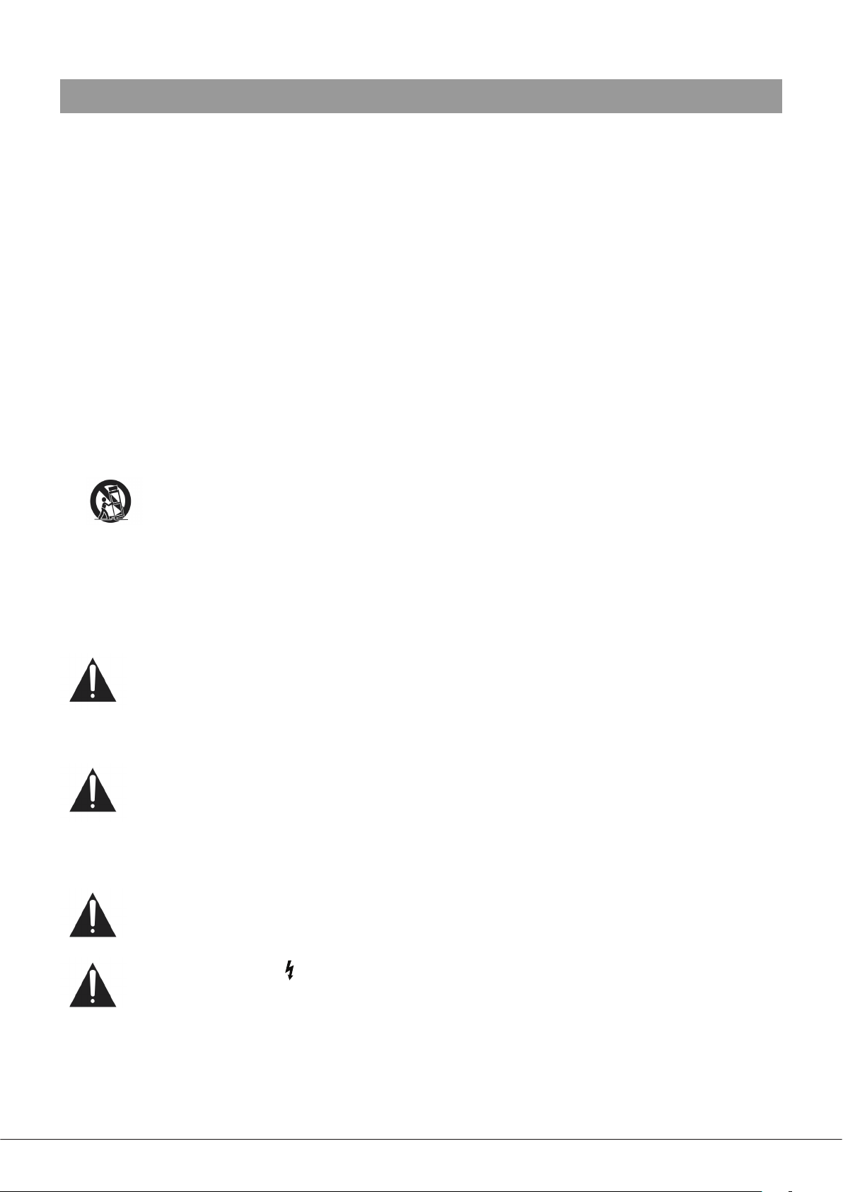
The LM-2 is an active input module with one microphone and
one stereo line input, which allows a microphone and a line
level audio source - such as a DJ mixer, laptop, MP3 player or
similar - to be connected to the 46-80 at a remote location.
The module also includes the functions of the RSL-6 Remote
Control Plate (see page 9), permitting control of zone music
level and source. A music ducking button activates the
46-80’s priority circuitry; when enabled, a microphone signal
from the LM-2 will reduce the music level in the zone. The
LM-2 connects to the 46-80’s FACILITY PORT, and thus will
generally be installed within Zone 1.
MUSIC LEVEL
6
7
5
7
4
8
9
3
10
2
1
0
LINE INPUT
8
9
10
PRIORITY
MIC
3
4
2
5
1
3
6
6
5
7
4
8
2
9
10
1
0
LM-2
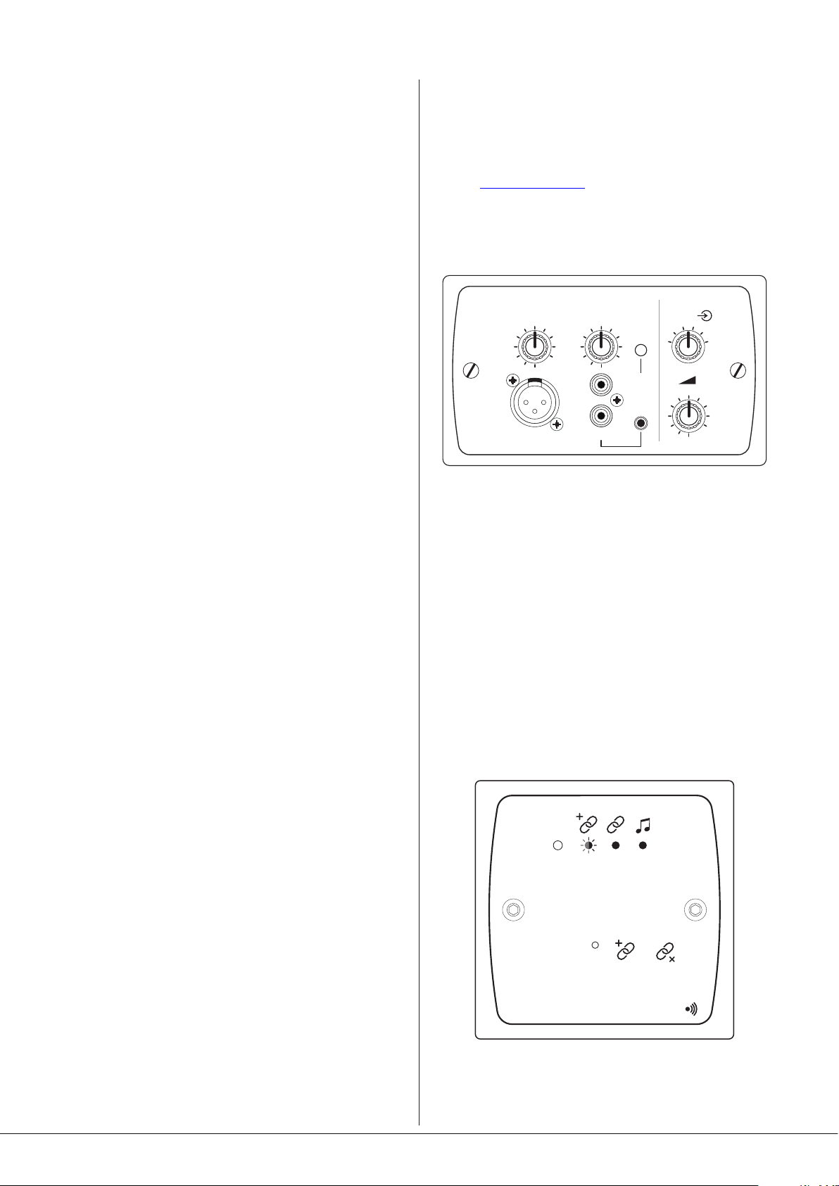
BT-1 Bluetooth wireless audio module
STATUS
--
TO PA IR
PUSH
The BT-1 is a Bluetooth remote audio input module which
enables compatible portable devices such as laptops, tablets
2s 5s
BT-1
8
46-80 Installation and User Guide V1.0
Page 9
and smartphones to stream audio wirelessly to the module,
and thus into the audio system of the area where the module
is installed. The 46-80’s priority circuitry is automatically
triggered when streamed audio is detected, reducing the
music level in the zone. The BT-1 connects to the 46-80’s
FACILITY PORT, and thus will generally be installed within
Zone 1.
M-1 Series Remote Mic Input module
sockets (RCA jacks) and a 3.5 mm 3-pole jack socket are
tted, together with a music level control. The L-1 connects
to the 46-80’s FACILITY PORT, and thus will generally be
installed within Zone 1.
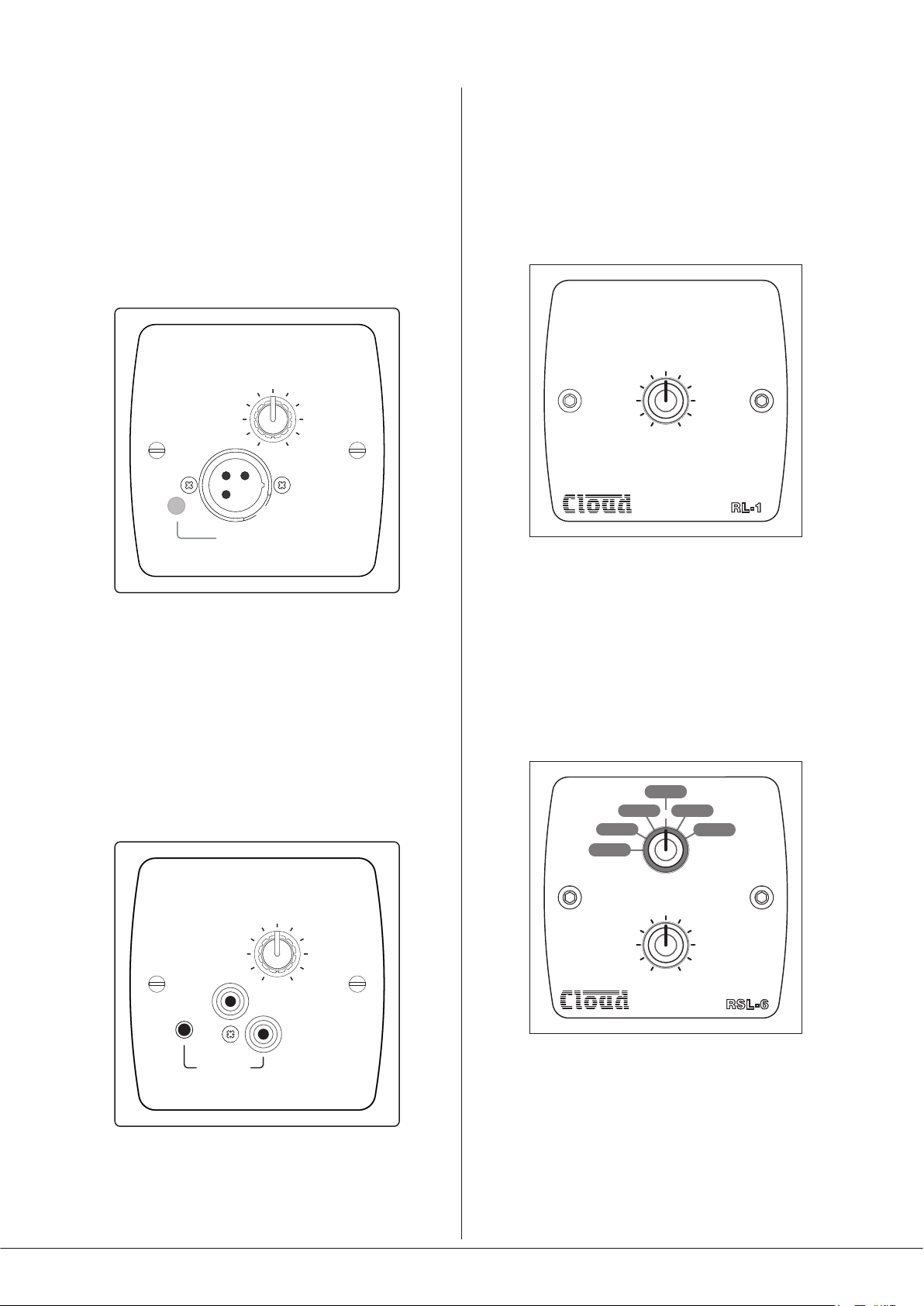
RL-1 Series Remote Music Level Controls
MIC LEVEL
5
6
4
3
2
1
0
MIC PRIORITY
7
8
9
10
M-1
The M-1 is a remote active input module which allows a
microphone to be connected within a zone and then routed
to the zone’s audio system. The module includes a mic level
control and a switchable mic-over-music priority function.
The M-1 connects to the 46-80’s FACILITY PORT, and thus
will generally be installed within Zone 1.
L-1 Series Remote Line Input module
5
6
4
3
2
1
MUSIC LEVEL
7
8
9
0
10
RL-1
The RL-1 Series is a range of small plates with a single control
for locally adjusting the music level in a zone. They connect
to one of the 46-80’s REMOTE MUSIC CONTROL ports.
RSL-6 Series Remote Music Level/Source Controls
345
2
1
6
MUSIC LEVEL
5
6
4
3
2
1
0
LINE INPUT
7
8
9
10
L-1
The L-1 is an active remote input module which allows a
stereo line level audio source to be connected within a zone
and then routed to the zone’s audio system. Both phono
SOURCE SELECT
5
6
4
3
2
1
MUSIC LEVEL
7
8
9
0
10
RSL 6-
The RSL Series is a range of plates allowing local (per-zone)
music source selection as well as music level control. They
are the same size as the RL-1s, and connect in a similar way.
The RSL-6, which provides 6-way source selection, is the
appropriate version for use with the 46-80.
46-80 Installation and User Guide V1.0
9
Page 10
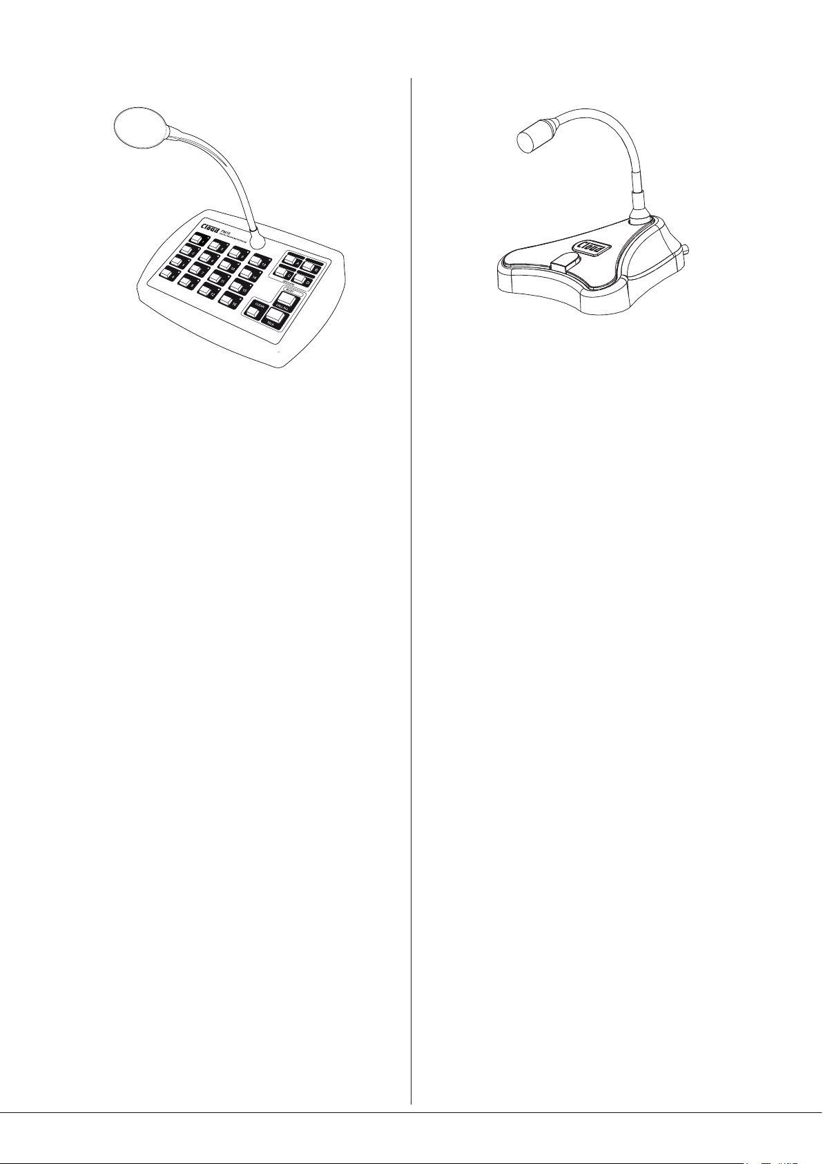
PM Series microphones
Cloud PM Series paging microphones may be connected
directly to the 46-80 using the DIGITAL PAGE MIC port using
Cat 5 cable. PM models are available for paging to 4, 8, 12
or 16 zones, and also to 4 or 8 zones with storage for builtin spot announcements. As the 46-80 only supports four
zones, not all zones available from the PM8, PM12 or PM16
can be accommodated by a single 46-80; the PM4 and
PM4-SA (4-zone) models are most likely to be useful.
The Cloud PM1 paging microphone is also compatible with
the 46-80. It is a much simpler unit which addresses a single
zone (although zones may be paralleled for wider access).
10
46-80 Installation and User Guide V1.0
Page 11
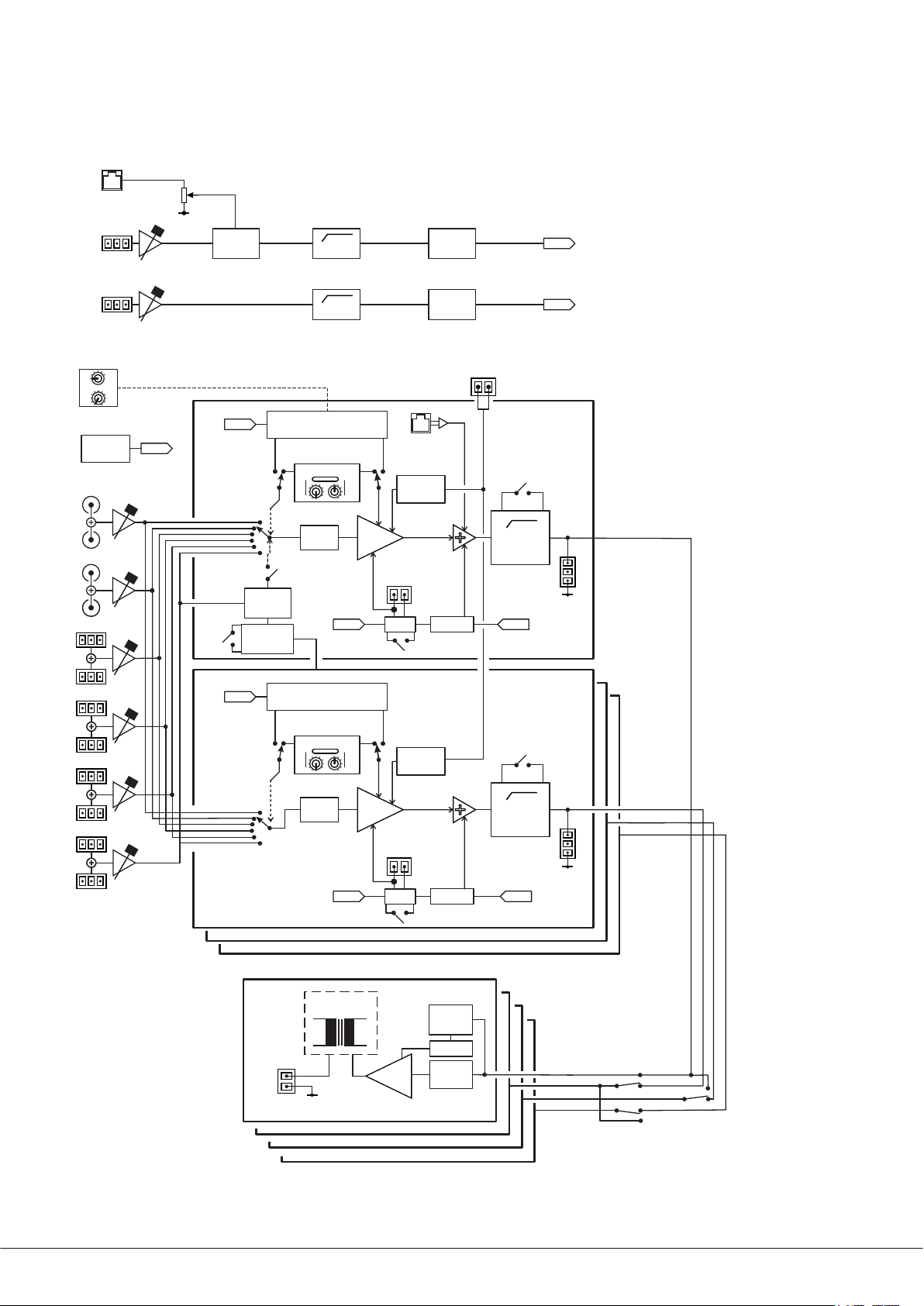
Block Diagram
DIGITAL
PAGE MIC
MIC 1
/PAGE
GATE
100Hz
MIC
EQ
MIC 1
LINE 1
LINE 2
LINE 3
LINE 4
MIC 2
OPTIONAL REMOTE CONTROL (RSL-6)
RS232
PORT
RS232
RS232
LINE 6 PRI
ZONE 1
LINE 6 PRI
ALL ZONES
RS232
100Hz
REMOTE MUSIC CONTROL
PORT
LOCAL CTRL
MUSIC
EQ
LINE 6
DETECT
REMOTE MUSIC CONTROL
PORT
VCA
MUSIC
PAGE
ACCESS
GATE
FACILITY
PORT
MUTE
PRIORITY
MIC
EQ
MUSIC MUTE
LOW PASS
FILTER
MIC 2MIC 1
ZONE 1
MIC 2
ZONE
AUX
OUT
LINE 5
LINE 6
LINE 6
LOCAL CTRL
MUSIC
EQ
70/100V LINE
(OPTION)
OUTPUT
ZONE 1 AMPLIFIER
ZONE 2 AMPLIFIER
ZONE 3 AMPLIFIER
ZONE 4 AMPLIFIER
VCA
MUSIC
PAGE
ACCESS
GATE
ENABLE
80W
MUTE
PRIORITY
SIGNAL
DETECT
TIMEOUT
LIMITER
LOW PASS
FILTER
MIC 2MIC 1
ZONE
AUX
OUT
ZONE 2
ZONE 3
ZONE 4
INTERNAL ZONE
ROUTING JUMPERS
The simplied block diagram above illustrates the basic signal architecture of the 46-80.
46-80 Installation and User Guide V1.0
11
Page 12

Front panel description
10
Only Zone 1 controls indicated :
those for the other Zones are identical
2
3
5610
1. SOURCE – 6-way rotary switch selecting which Line Input (LINE 1 to LINE 6) will be the music source for each zone.
2. MUSIC LEVEL – adjusts the music level in each zone.
7 8 91010
1
411
3. MIC 1 – adjusts the level of the microphone connected to the rear panel MICROPHONE 1/PAGE MIC input in each zone.
4. MIC 2 – as [3], but controls level of MICROPHONE 2 input.
5. MUSIC EQ – two preset controls for adjusting HF/LF EQ in each zone:
• LF: +/-10 dB @ 50 Hz
• HF: +/-10 dB @ 10 kHz.
6. PEAK – per-zone red LEDs; illuminate if the output stage’s limiter detects clipping, indicating that the level is too high.
7. POWER – bi-colour LED indicating power status:
• steady green – active
• steady red – sleep (APD) mode
• ashing red – fault condition (over-temperature, DC protection, speaker wiring error or over-current);
power-cycle to clear
8. LINE IN DETECT – green LED; illuminates when an input signal is detected at any of the Line Inputs.
9. MUTE – red LED; illuminates when the MUSIC MUTE function is active.
10. Fixing holes for security cover – prevents access to Zone EQ controls.
11. Ventilation slots – do not block.
12
46-80 Installation and User Guide V1.0
Page 13

Rear panel description
6 6 8 910 13 19 16
20 21
3 3 3 3 3 3 11 1814 12 15
7 7
54
1 2 2 17
1. LINE 1 and LINE 2 – unbalanced line inputs for connection of music sources. Two pairs of RCA (phono) sockets; inputs are
stereo and summed internally to mono.
2. LINE 3 to LINE 6 – balanced line inputs for connection of music sources. Four 3-pin, 3.5 mm-pitch screw-terminal
connectors; inputs are stereo and summed internally to mono.
3. GAIN – preset trim control for each line input, providing +/-10 dB of gain adjustment for input level matching.
4. MICROPHONE 1/PAGE MIC – balanced microphone input on 3-pin 3.5 mm-pitch screw-terminal connector. This input
may be used in conjunction with the MIC 1 ACCESS connector [8] for paging.
5. MICROPHONE 2 – balanced input for a second microphone; 3-pin 3.5 mm-pitch screw-terminal connector.
6. GAIN – preset mic gain trim controls for each mic input, gain range 10 to 48 dB.
7. MIC EQ – two preset EQ controls for each mic input:
• LF: +/-10 dB @ 100 Hz
• HF: +/-10 dB @ 5 kHz
8. MIC 1 ACCESS – 6-pin, 3.5 mm-pitch screw-terminal connector for paging zone selection by contact closure.
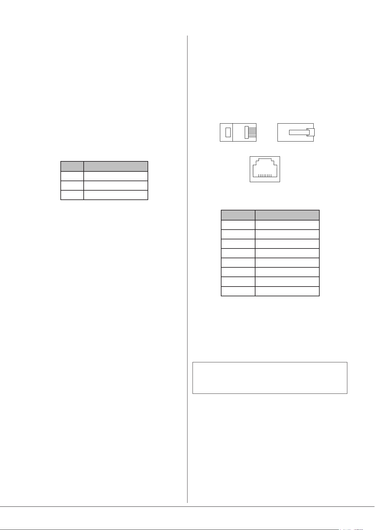
9. DIGITAL PAGE MIC - RJ45 Cloud Digital Paging interface; PM Series* microphones (excluding the PM1) may be connected
here, using Cat 5 cable.
10. SW1: CONFIG – 5-pole DIP switch for setting various unit congurations:
SWITCH FUNCTION PURPOSE
1
2
3
4
5
11. REMOTE MUSIC CONTROL – 3-pin 5 mm-pitch screw terminal connector for each zone, for connection of RL-1/RSL-6
remote control plates.
MIC 1 PHANTOM PWR
MIC 2 PHANTOM PWR
MIC OVER MUSIC
MUTE – N/O OR N/C
PAGING MODE
Enables 15 V phantom power for Mic 1
Enables 15 V phantom power for Mic 2
Enables mic-over-music priority
Congures MUSIC MUTE input
Congures Mic 1 Input for paging
12. SW2: CONTROL – 8-pole DIP switch determining whether front panel music source and/or level controls will remain
active when remote control plates are connected (per-zone).
13. FACILITY PORT [ZONE 1] – RJ45 socket, for connection of optional remote input/control modules; may also be used as
an auxiliary input.
* The earlier Cloud CDPM range of Paging Microphones is also compatible with this interface.
46-80 Installation and User Guide V1.0
13
Page 14

14. AUX OUT – line level outputs for Zone 1 and Zone 2. Outputs are balanced at 0 dBu, and are derived prior to the power
amplier stages.
15. SW3: UTIL/PRI/APD – 8-pole DIP switch for setting further unit congurations:
SWITCH FUNCTION PURPOSE
1
2
3
4
5
6
7
8
16. SPEAKER OUTPUTS – amplier outputs for each of the four zones, on 2-pin 5 mm-pitch screw-terminal connectors per-
zone. Outputs will be low impedance (4 ohms) on Model 46-80, and either 70 V-line or 100 V-line (territory-dependent)
on Model 46-80T or on Model 46-80 if CXL-80T transformers have been retrotted.
17. UTILITY/LOOP OUTPUT - an auxiliary output carrying a mix of music and mic inputs, whose music source can be set
by DIP SWITCH SW3 [15]. The output is balanced, and at line level (0 dBu). The output has two associated preset level
controls, MIC and MUSIC.
18. RS232 - a 3-pin 3.5 mm-pitch screw-terminal connector providing a bi-directional RS-232 interface. This accepts
commands to select or adjust various 46-80 functions and parameters from an external AV control system.
19. MUSIC MUTE – 2-pin 5 mm-pitch screw terminal connector for connection of external emergency muting relay (e.g., re
control panel).
APD ON
APD TIMING
LINE 6: PRIORITY Z1
LINE 6: PRIORITY ALL
UNUSED
UTILITY SOURCE A
UTILITY SOURCE B
UTILITY SOURCE C
Enables automatic standby mode
Sets delay before entering APD mode
Enables Line 6 priority for Zone 1 only
Enables Line 6 Priority for all Zones
Select source for UTILITY/LOOP OUTPUT
20. Mains – IEC receptacle for AC mains. The receptacle has an integral fuseholder. The 46-80 will operate on all AC supply
voltages from 85 to 243 V, 47 to 63 Hz.
21. Power switch.
14
46-80 Installation and User Guide V1.0
Page 15

INSTALLATION
LEFT
T
pi
pi
pi
Balanced
the mixer amplier has developed a fault, which should be
referred to competent service personnel.
Hardware considerations
The 46-80 Mixer Amplier is built in a 2U-high 19” rack
mount enclosure. It is recommended that it is installed in a
19” rack wherever possible. The units are approx. 320 mm
deep, but at least 400 mm of rack depth should be available
to allow for rear connectors and cabling.
The choice of installation location will be dictated by the
specics of the system and building layout. It is recommended
that wherever possible, the 46-80 should be mounted
adjacent to as many of the music sources (CD players, music
servers, TV receiver boxes, etc.) as practical.
When deciding the Mixer Amplier’s location, bear in mind
that access to it (particularly the rear panel) will probably
be required even if a full complement of remote controls is
being tted as part of the system, as certain adjustments can
only be made on the unit itself
Ventilation
The 46-80 is convection-cooled: the absence of fans makes it
silent in operation. There are ventilation slots in the front and
rear panels, the top and bottom panel and the right-hand side
panel: ensure that these are kept unobstructed by cabling or
any other items.
The 46-80 has been designed to operate in an ambient
temperature range of 0°C to 35°C. While satisfactory
operation outside of this recommended temperature range
may be achievable in a particular installation, no guarantee
can be given regarding full adherence to the performance
specications (see the Appendix section of this manual).
Installers should always endeavour to t the 46-80 in a
location where the recommended temperature range is not
exceeded. To help achieve this, we recommend that the 46-80
is not rack-mounted immediately above other equipment which
generates heat (e.g., older designs of power amplier).
If the unit is to be used free-standing (i.e., not mounted in a
rack), the four self-adhesive feet supplied in the accessory
pack should be tted to the bottom of the enclosure.
Power Supply
The 46-80 has an internal power supply of the “universal”
type, and will operate on all AC mains supplies of between
85 V and 243 V, 47 to 63 Hz. An IEC mains cable with a plug
appropriate for each country is supplied with the unit. The
46-80 is very energy-efcient and only consumes 20 W in
Idle mode; see the Technical Specications at page 34 for
more details.
Fuses and ratings
The only externally-accessible fuse is an AC mains fuse on
the rear panel. Only replace a fuse with one of exactly the
same type. The table below gives the correct fuse type:
Fuse Type Fuse size Rating
T5AH 250V 20 mm x 5 mm 5 A
If a replacement fuse blows immediately, it indicates that
Internally, a 20mm x 5mm fast-blow 5A fuse protects each
two-channel amplier module. These are service components,
and should not require attention. Failure of these fuses
indicates a fault condition, which should be immediately
referred to a competent technician or authorised service
centre.
System connections
Music sources
Connect the system’s various music sources to inputs
LINE 1 to LINE 6. Line Inputs 1 and 2 are unbalanced, on
standard RCA jacks (phono sockets), while Line Inputs 3
to 6 are balanced, on 3-pin 3.5 mm-pitch screw-terminal
connectors. All six inputs are stereo, with separate L and R
connectors. The sensitivity range available should allow
most standard items of audio equipment such as computers/
tablets, music servers and media receivers, etc., to operate at
a satisfactory level.
Balanced and unbalanced sources:
Source equipment with stereo unbalanced outputs may be
connected directly to Line Inputs 1 or 2, and as long as the
source is adjacent to the Zone Mixer, normal phono-phono
(or 3.5 mm jack-to-phono leads) can be used. Always avoid
using pre-made leads of an unnecessary length.
Source equipment with stereo balanced outputs should be
connected to Line Inputs 3 to 6, using twin-and-screen cable
and the pinout below:
PIN CONNECTION
1 Screen
2 Signal ‘-‘ (cold)
3 Signal ‘+’ (hot)
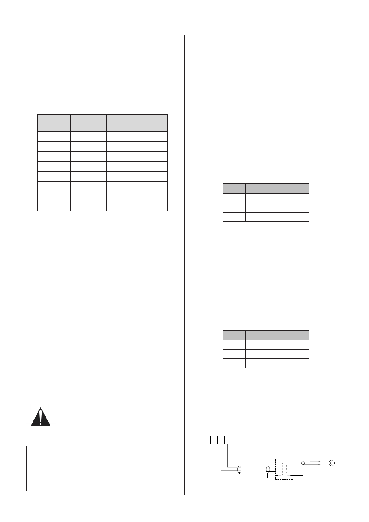
If it is necessary to connect an item of source equipment with
a balanced output to Line Inputs 1 or 2, the ideal method is
to use a balancing transformer between the source and the
unbalanced input. Suitable audio transformers, which should
have a ratio of 1:1, are readily available from major audio
component suppliers. The transformer(s) should be mounted
as close to the Zone Mixer as practical, and housed in a
screened enclosure if they are not individually screened. The
preferred connection method is shown below:
outputs (XLRs):
n1ground
n2hot
n3cold
LEFT
3
12
RIGHT
3
12
-
+
SCN
-
+
SCN
Audio balancingtransformers
-
+
SCN
-
+
SCN
SCN
SCN
Unbalanced
inputs
RIGH
Unbalanced
inputs
46-80 Installation and User Guide V1.0
15
Page 16
Mono and stereo sources:
The mixing section of the 46-80 is mono; the stereo line inputs
are summed internally. Stereo sources should be connected
in a normal stereo conguration, using both L and R inputs. If
connecting a mono source with only a single output, it may
be connected to either the left or the right input.
Microphone inputs
Inputs MICROPHONE 1/PAGE MIC and MICROPHONE 2 are
intended for the direct connection of microphones. They are
electronically balanced and transformerless with an input
impedance of greater than 2 kohms and optimised for use
with microphones of 200 to 600 ohms impedance. The screw
terminal input connectors should be wired thus:
PIN CONNECTION
1 Screen
2 Signal ‘-‘ (cold)
3 Signal ‘+’ (hot)
The port is able to supply 250 mA to power paging
microphones. This is adequate to power one or two PM-4
microphones. Cloud recommend that all ‘-SA’ models (with
spot announcement sound stores) are powered by a separate,
external PSU, as described in the PM Series Installation Guide.
(A suitable PSU is supplied as standard with all ‘-SA’ models.)
Connect the OUT socket of the PM Series microphone
to the DIGITAL PAGE MIC socket on the Zone Mixer with
Cat 5 cable. The standard Cat 5/RJ45 wiring convention is
shown below:
Unbalanced microphones may be used by connecting pin 2
to pin 1 (cable screen) in the mating (male) screw-terminal
connector. 15 V phantom power is available, see page 22.
Either mic input may be routed to any of the zones in use,
at any level in each zone. Microphone priority may be set so
that any microphone announcements automatically reduce
the music level in that zone while the announcement is in
progress (see page 23 for more details.)
Paging system connections
Cloud PM Series paging microphones may be connected
directly to the 46-80. All models except the PM1 can use
either the Cloud Digital Paging Interface or an industrystandard analogue interface; Model PM1 uses the analogue
interface.
PM microphones are available in 4, 8, 12 or 16-zone versions;
the PM-4 (or PM-4SA) is the appropriate model for use with
the four-zone 46-80.
Whichever connection method is employed, in order for
MICROPHONE 1/PAGE MIC 1 to function correctly with a
paging mic, rear panel DIP switch SW1/5 (PAGING MODE)
should be set to PG (switch down). For automatic music
ducking during an announcement, DIP switch SW1/3 (MIC
OVER MUSIC) should be set to ON (switch down). See page
23 for further information.
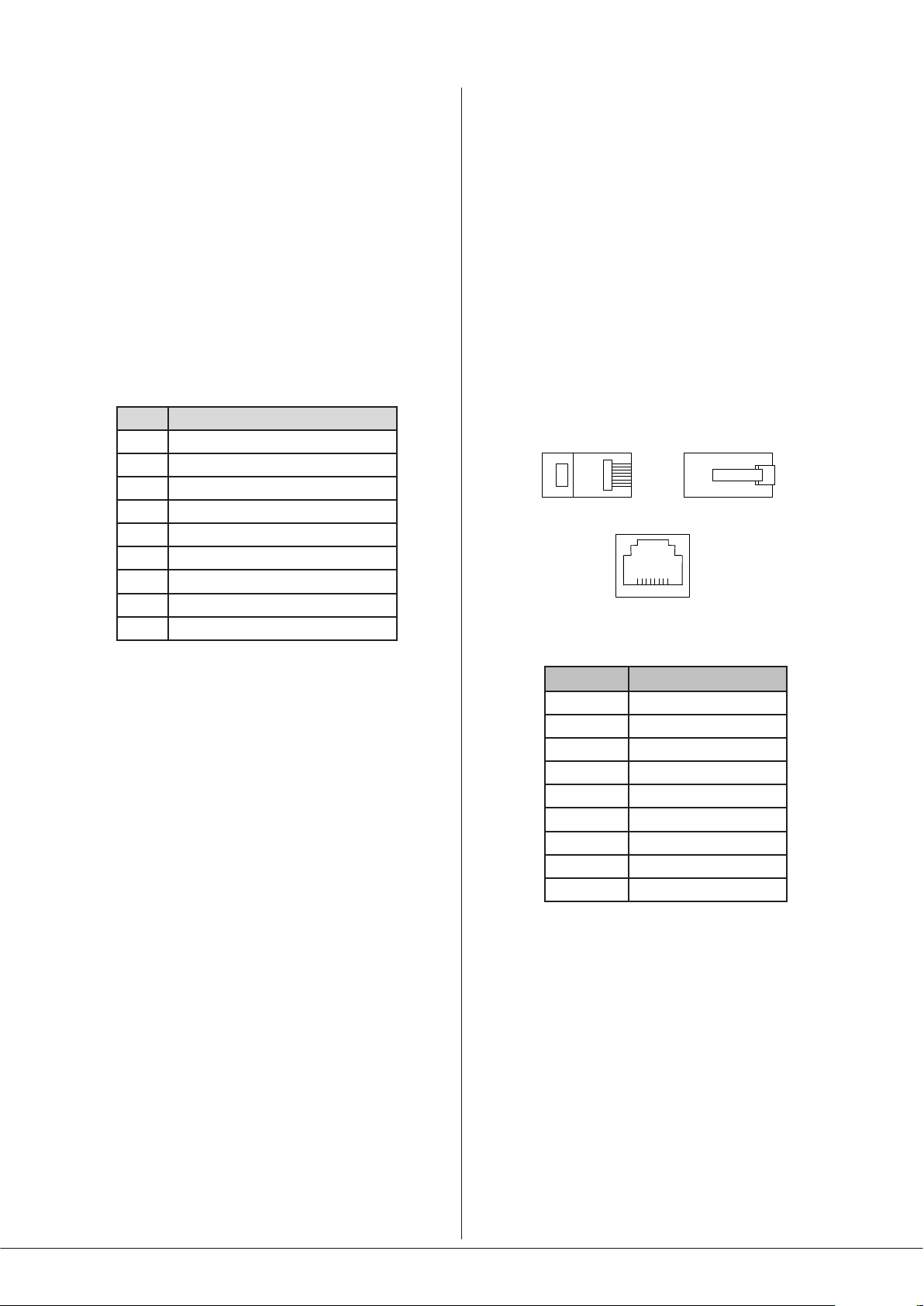
RJ45 PIN CAT5
1 Brown + White
2 White + Brown
3 Green + White
4 White + Blue
5 Blue + White
6 White + Green
7 Orange + White
8 White + Orange
The Cloud Digital Paging Interface allows multiple PM
Series microphones to be “daisy-chained”. If more than one
paging microphone is being installed – typically at different
locations in the building, connect the OUT socket of one to
the IN socket of the next.
IMPORTANT - Please refer to the PM Series Installation
Guide for full information regarding maximum cable
length, buss terminations and current requirements.
The earlier Cloud CDPM Series of paging microphones is also
compatible with the Digital Paging Interface.
Connecting a PM4/4SA paging mic via the Cloud
Digital Paging Interface
The 46-80 is tted with a Cloud Digital Paging Interface; this
uses a RJ45 socket and is indicated as the DIGITAL PAGE MIC
connector on the rear panel ([9] at page 13). Cloud PM
Series Paging microphones may be connected directly with
Cat 5 cable; the single connection provides all audio, control
and power required by the microphone.
16
46-80 Installation and User Guide V1.0
Page 17
Connecting a PM4/4SA paging mic via the
analogue interface
Two connections are required: the paging mic audio signal
should be connected to the MICROPHONE 1/PAGE MIC
Input ([4] on page 13) and the control cable to the 6-pin
MIC 1 ACCESS port ([8] on page 13). The pinout of the port
is given below:
PIN FUNCTION
1 0 V
2 Zone 1
3 Zone 2
4 Zone 3
5 Zone 4
6 +Vsupply
Standard two-core screened audio cable may be used for
the audio signal, and stranded six-core cable with an overall
screen for the control cable. (Note that ‘-SA’ versions of PM
Series microphones cannot be powered by the 46-80, and
require an external PSU.)
Connections on the PM microphone are made via the rear
cable access glands and screw terminal blocks on the internal
PCB (TERM1, TERM4 and TERM8 in the example shown
below). Full connection details and notes on power supply
considerations can be found in the PM Series Installation and
User Guide.
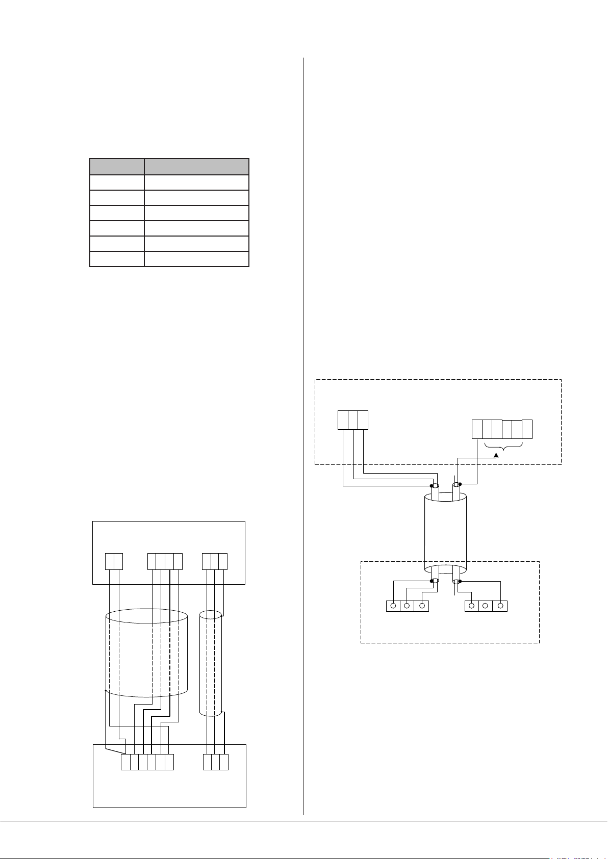
The diagram below shows both cable connections between a
PM4 and a 46-80. Note that the DC power supply connection
will not be required if the PM microphone is powered
independently (either by a local PSU or via the network from
another PM unit).
Connecting a PM1 paging mic
The PM1 is a simple, passive paging microphone suitable for
situations where announcements are always made to the
same zone(s). It can be connected directly to the 46-80’s
analogue paging interface, the control cable being wired to
the pin(s) of the MIC 1 ACCESS port corresponding to the
zone(s) in which announcements are required. Any or all of
the zones may be paralleled if multiple zones need to operate
from the PM1.
Either a single 2-pair individually-screened cable may be
used (this gives the neatest nish), or two separate standard
microphone cables. Note that the PM1 does not require
DC power. Connections on the PM1 are made via the rear
cable gland in the base and the screw terminal blocks on
the internal PCB (U2 and U3). Full connection details can be
found in the PM1 Installation and User Guide.
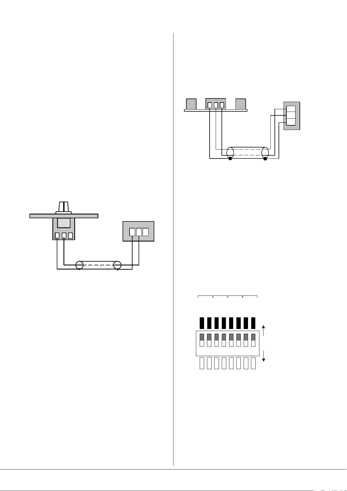
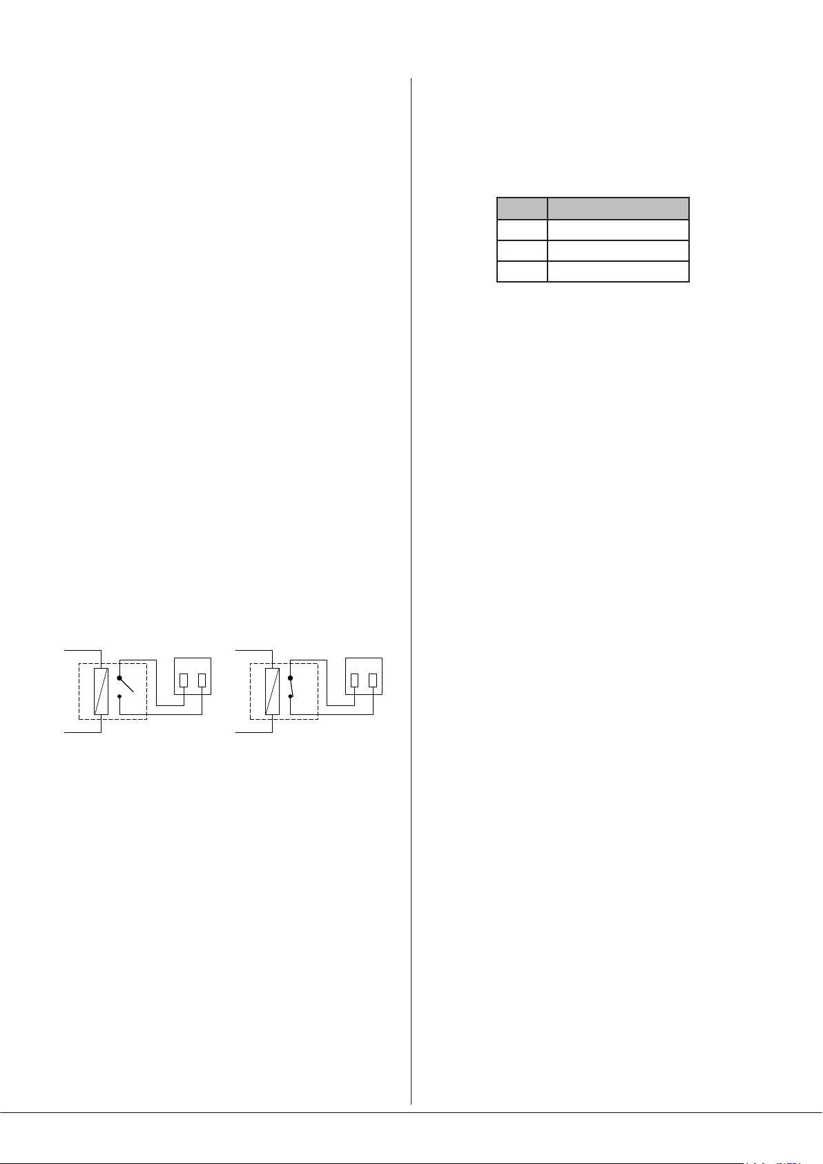
The diagram below shows the connections between a PM1
and a 46-80. Use of 2-pair cable is assumed; the same wiring
principle is adopted if separate cables are being used for
audio and control.
MICROPHONE INPUT
MIC 1 ACCESS
2 3
1
46-80
+
-
scn
0 V
Z4
Z1 Z2 +V
Z3
CONNECT TO
ZONE(S) IN USE
PM4 PAGING MICROPHONE
0 V
+ V
0 V
Z4
+ V
46-80 MIXER
AMPLIFIER
TERM8TERM2TERM1
HOT COLDGNDZ1 Z2 Z3
Z4
SCN
COLD
HOT
U2 AUDIO
HOT COLDGNDZ1 Z2 Z3
MIC 1 INPAGING ACCESS
PM1
GNDN/CN/O
U3 ACCESS
46-80 Installation and User Guide V1.0
17
Page 18
Remote music control
Like most other Cloud host units, the 46-80 allows remote
control of music level and source selection in each of the
primary zones (i.e., excluding the Utility/Loop output). Cloud
remote control plates from the RL-1 Series (music level only)
and RSL-6 Series (music level and source selection) provide
an elegant solution, though control via a DC voltage from
third-party systems is also possible (see page 28).
Both types of plate connect via the REMOTE MUSIC
CONTROL connectors for the relevant zone (see [11] on
page 13). These connectors are 3-pin 5 mm-pitch screw
terminal type.
Connecting an RL-1 Series remote control plate
Wire the remote control plate as shown below using screened
cable as shown. Maximum reliable cable run is 100 m.
REMOTE LEVEL CONTROL WIRING
RL-1
REMOTE
MUSIC CONTROL
123
123
Connecting an RSL-6 Series remote control plate
Wire the remote control plate as shown below. Twin-andscreen cable should be used. Maximum reliable cable run is
100 m.
REMOTE SOURCE & LEVEL CONTROL WIRING
REMOTE
123
RSL-6
USE TWO-CORE SCREENED CABLE
Before the RSL-6 will operate, the zone’s Remote Music
Control Port must be enabled by setting the appropriate
two sections of rear panel DIP switch SW2 ([12] on page
13) to REM (switches down). Note that separate switch
sections independently enable the music level and music
source selection for each zone: for an RSL-6 to work fully,
both sections must be set to REM. With this setting, the
zone’s front panel MUSIC LEVEL and SOURCE controls will
be inoperative. The user may wish to limit the functionality
of an RSL-6 to only music source selection (i.e., no remote
control of volume), in this case only the even-numbered
switch sections should be set to REM.
MUSIC CONTROL
3
2
1
SINGLE-CORE SCREENED CABLE MAY BE USED
Before the RL-1 will operate, the zone’s Remote Music
Control port must be enabled by setting the appropriate
section of rear panel DIP switch SW2 ([12] on page 13) to
REM (switch down). The odd-numbered sections of SW2 are
used to enable remote level control, as shown in the adjacent
diagram. When set to REM, the zone’s front panel MUSIC
LEVEL control becomes inoperative. Music source selection
will still be available from the mixer amplier’s front panel
when an RL-1 is in use.
SW2
ZONE 1 ZONE 4ZONE 3ZONE 2
SOURCE
LEVEL
LEVEL
LOC
LOC
LOC
1 2 3 4 5 6 7 8
REM
REM
REM
SOURCE
LEVEL
LOC
LOC
REM
REM
SOURCE
LEVEL
LOC
LOC
REM
REM
SOURCE
LOC
Set to LOC to control
source/level from front panel
REM
Set to REM to control
source/level from remote plate
18
46-80 Installation and User Guide V1.0
Page 19
Zone 1 Facility Port
Zone 1 of the 46-80 is provided with a FACILITY PORT in the
form of an RJ45 connector on the rear panel ([13] on page
13). This may be used to connect a Cloud remote active
input/control module, but may also be used as a generalpurpose auxiliary balanced input (see Page 29 for more
information on this application). Note that an audio source
connected via the FACILITY PORT will only be available in
Zone 1, and no other.
Active modules operate from DC power supplied by the
46-80. The current consumed by each module is minimal and
in the vast majority of installations there will be no power
supply issues.
The pinout of the FACILITY PORT connector is given in the
table below:
PIN USE
1 Remote source select
2 Remote level control
3 Balanced audio input hot (+)
4 Balanced audio input cold (-)
5 Noise Gate control
6 -Vsupply
7 +Vsupply
8 0 V DC
9 VCA control voltage
Connecting an active remote module
The following Cloud active remote input modules are directly
compatible with the 46-80 and may be connected to the
FACILITY PORT using screened Cat 5 cable:
• LM-2 combined mic/line input and music source/level
control module
• BT-1 Bluetooth wireless input module
• L-1 stereo line input module
• M-1 balanced mic input module with priority control
Note that as the cable carries analogue audio, only screened
Cat 5 should be used. All the remote modules listed above
use RJ-45 connectors as their interface: ready-made screened
Cat 5 cables may be used if suitable lengths are available.
Otherwise, install bulk screened Cat 5 cable and t crimpable
screened RJ45 connectors, using the standard wiring
convention:
RJ45 PIN CAT5
1 Brown + White
2 White + Brown
3 Green + White
4 White + Blue
5 Blue + White
6 White + Green
7 Orange + White
8 White + Orange
RJ45 can Cable screen
NOTE: The LM-2 has an IN connector as well as an OUT: this
allows multiple LM-2s to be “daisy-chained”. If more than
one LM-2 is being installed – typically at different locations
in the same zone, connect the OUT socket of one to the IN
socket of the next.
46-80 Installation and User Guide V1.0
19
Page 20
Speaker outputs (Lo-Z)
The power amplier outputs on Model 46-80 are available
on an 8-pin, 5 mm-pitch screw-terminal connector SPEAKER
OUTPUTS ([16] on page 13): rst remove the safety cover
protecting it (2 x M3 screws). Four mating 2-pin connectors
are supplied; the outputs for all four zones are present on the
connector. Connect to speakers using pairs of terminals as
shown in the table:
Pin (L to R) Panel
marking
1
2
3
4
5
6
7
8
Z1 -
Z1 +
Z2 -
Z2 +
Z3 -
Z3 +
Z4 -
Z4 +
Connect to:
Zone 1 output ‘-’
Zone 1 output ‘+’
Zone 2 output ‘-’
Zone 2 output ‘+’
Zone 3 output ‘-’
Zone 3 output ‘+’
Zone 4 output ‘-’
Zone 4 output ‘+’
When the 46-80 is congured for 100/70 V-line operation,
the 65 Hz high-pass lters in each zone to be used in this
mode should be enabled: this is done by moving internal
jumpers. Model 46-80T has the lters pre-enabled at the
factory. See page 24 for full details.
Utility/Loop output
The UTILITY/LOOP OUTPUT is an additional balanced
line level output which is primarily intended for driving an
external hearing loop amplier, but can also can be used for
any other purpose. The source may be the programme in any
of the four Zones or always either Line Input 1 or Line Input
6, and is selected by rear panel DIP switches. See page 24
for full details.
The output connector is a 3-pin, 3.5 mm-pitch screw terminal
type ([17] on page 13), wired as follows
PIN CONNECTION
1 Screen
2 Signal ‘-‘ (cold)
3 Signal ‘+’ (hot)
Each output stage is designed to drive into an impedance
of not less than 4 ohms. Check the impedance of the
loudspeaker(s) in use and, taking into account any series and/
or parallel wiring, ensure that the total load on each channel
is not less than 4 ohms.
Speaker outputs (70/100 V-line operation)
Model 46-80T has four CXL-80T transformers pre-installed
and is thus ready for 70/100 V-line operation. Any or all zone
outputs of Model 46-80 may be converted for 70/100 V-line
operation by retrotting CXL-80T transformers as necessary.
See page 29 for details of CXL-80T transformer installation.
Note that immediately below the SPEAKER OUTPUTS
connector the rear panel is printed with check boxes marked
4 OHMS and 70/100V to indicate how the output is
congured for each zone. These will be marked according to
model type (46-80 or 46-80T) prior to shipment.
In Model 46-80T, the factory-tted CXL-80Ts are wired for 70
V-line operation in units for North American territories and
Australia, and for 100 V-line operation in units for Europe.
This can be changed if wished by moving internal connectors.
Use the same speaker wiring as shown for lowimpedance operation in the table above.
Ensure that the unit is disconnected from the AC
mains supply when making connections to avoid any risk of
electric shock
IMPORTANT - After making the connections and plugging
in the mating connectors, ret the safety cover over the
SPEAKER OUTPUTS socket. Making contacts carrying
70 V or 100 V inaccessible is likely to be a legal requirement
in most territories.
Auxiliary line outputs
In large zones, it may be necessary to use additional ampliers
to obtain the necessary power to drive a greater number of
loudspeakers, or to drive some loudspeaker types requiring
higher power levels than the 80 W available from each of
the 46-80’s outputs. To permit the connection of further
ampliers - or any other equipment - balanced outputs from
Zones 1 and 2 pre-amplier sections are available at the rear
panel AUX OUT connectors, [14] at page 13.
The two connectors are of 3-pin, 3.5 mm-pitch screw terminal
type. Wire using the pinout in the table below:
PIN CONNECTION
1 Screen
2 Signal ‘-‘ (cold)
3 Signal ‘+’ (hot)
Connect to balanced inputs on external equipment with
twin-and-screen cable. The auxiliary outputs may also be
connected to unbalanced inputs: Cloud recommend the use
of external balancing transformers to achieve this, as shown
below:
AUX OUT:
pin 1 ground
pin 2 hot
pin 3 cold
1 32
Audio balancing transformer
-
+
SCN
-
+
SCN
SCN
Unbalanced
input
20
46-80 Installation and User Guide V1.0
Page 21
If balancing transformers are not available, satisfactory
results are likely to be obtained by connecting pin 3 to the
signal pin of the unbalanced input (e.g., the tip of a phono/
RCA connector) and pin 1 to the connector’s outer screen. Do
not connect pin 2.
Note that all Zone 1 and 2 controls and settings on the front
and rear panels (levels, source selection, priority settings,
etc.) affect the auxiliary outputs.
Music Mute
External muting of music is available at the MUSIC MUTE
connector. Note that Music Muting only applies to Zone
Outputs 1 to 4 and the Auxiliary Outputs, and not to
the UTILITY/LOOP output. National or Local Authority
regulations governing such systems may require that normal
programme material (i.e., music) should be muted in an
emergency, to ensure that any emergency messages are
clearly audible.
The MUSIC MUTE input is on a 2-pin 5 mm-pitch screwterminal connector. It should be connected to the appropriate
alarm output on whichever building management system
registers the alarm (typically the Fire System). The alarm
output must be volt-free; if no such output is available, an
intermediate relay or other isolation device must be installed
between the alarm output and the Music Mute input.
RS232 Serial Port
The 46-80 can accept commands from third-party AV
systems using standard RS232 protocol. A bidirectional serial
port - marked RS232 - is available on the rear panel ([18]
on page 13). This is a 3-pin, 3.5 mm-pitch screw-terminal
connector, and should be wired as below:
PIN CONNECTION
1 0 V
2 Data Rx
3 Data Tx
Note that not all control systems interpret “Tx” and “Rx” the
same way, and the installer should check whether pins 2 and
3 should be “crossed” within the cable.
See Page 26 for more details of RS232 control and an abridged
command set.
Music Muting can be triggered by either normally-open
contacts, or normally-closed contacts. This selection is made
by rear panel DIP switch SW1/4 (MUTE – N/O OR N/C): the
default setting is N/O.
REMOTE MUSIC MUTE TERMINATIONS
RELAY
NORMALLY OPEN (NO)
CONNECTION
MUSIC MUTE
INPUT
1 2
RELAY
NORMALLY CLOSED (NC)
CONNECTION
MUSIC MUTE
INPUT
1 2
The red MUTE LED on the front panel ([9] on page 12)
illuminates when Music Muting is active
46-80 Installation and User Guide V1.0
21
Page 22

SETTING UP & OPERATION
Music Inputs
Gain & level
To avoid dramatic changes in volume when switching
between sources, the 46-80’s music inputs are provided
with preset gain trim controls ([3] on page 13). These
vary the input sensitivity from -12 dBu (195 mV) to
+8 dBu (2.0 V). When setting the system up, play audio from
all the sources in use and listen to them one at a time in a
convenient zone (ideally that in which the mixer is located)
at a reasonable volume. Taking a source of “average” volume
as the reference, the gain controls of the others should be
adjusted so that there is no appreciable difference in volume
between any of the sources. (With a typical music source,
setting the gain on its channel to mid-way is a good starting
point.) Note that consideration may need to be given to the
type of programme in use, particularly if one or more sources
are TV sound.
In normal operation, the music level in each primary zone
is set with the MUSIC LEVEL control on the front panel
([2] on page 12). This control will not be operative if the
corresponding section of rear panel DIP switch SW2 is set to
REM.
Note that the setting of the music level has no effect on
microphone volume.
The front panel is tted with a green LINE IN DETECT LED
([8] at page 12). which illuminates if a signal is present at
any of the six Line Inputs: note that the signal detection is
post the rear panel GAIN controls. The LED’s threshold level
is -30 dB, with a GAIN control setting of 0 dB. The LINE IN
DETECT LED is a useful aid to system troubleshooting as it
conrms that a music source signal is present at the 46-80.
Each of the four Zones has a front panel PEAK LED ([6] at
page 12), which illuminates if the signal level in the power
stage approaches clip level. This will probably indicate that
either the music level or the microphone level is set too high
and should be reduced.
Microphone input
Phantom power
Both microphone inputs have 15 V phantom power available.
This will be adequate to power a wide range of condenser
microphones. (Some “studio quality” mics may require a
higher phantom voltage and thus necessitate an external
PSU.) To enable phantom power at a mic input, set rear panel
DIP switch SW1/1 (MIC 1) and/or SW1/2 (MIC 2) should be
moved to the ON position (switch down).
Phantom power should NOT be enabled if dynamic
microphones are to be used.
Gain & level
Each microphone input is provided with a rear panel preset
GAIN control ([6] on page 13). A wide range of gain is
available and there should be no problem in obtaining a
satisfactory level from any normal microphone.
The GAIN controls should be adjusted by speaking normally
into a microphone of the correct type. Turn the relevant
front panel MIC LEVEL control up to maximum and listen
in a convenient zone; the rear panel gain control should be
carefully advanced until the mic volume is as loud as it is ever
likely to be needed, and then reduced slightly. There should
be no audible distortion. The use to which the microphone is
to be put should be borne in mind – karaoke is more likely to
overload the mic preamplier than spoken announcements,
if the gain is not set correctly.
In normal operation, the mic level in each zone is set with
the MIC LEVEL controls on the front panel ([3] and [4] on
page 12).
Each of the four Zones has a front panel PEAK LED ([6] at
page 12), which illuminates if the signal level in the power
stage approaches clip level. This will probably indicate that
either the music level or the microphone level is set too high
and should be reduced.
EQ
Local/remote control
If a zone has an RL-1 or RSL-6 Series remote control plate
installed, the two sections of rear panel DIP switch SW2
– LEVEL and SOURCE – for the zone in question must be
set to REM (switches down) for the remote controls to be
operative and for the corresponding front panel controls to
be disabled. Zones without such plates should be set to LOC
(both switches up).
Note that unlike earlier Cloud host units, remote control
of music level and music source selection can be enabled
independently of each other. There are no internal jumpers
affecting the remote music control conguration.
22
46-80 Installation and User Guide V1.0
Each mic input has associated HF and LF EQ controls ([7] on
page 13) These provide 10 dB of cut or boost at 5 kHz and
100 Hz respectively and should be adjusted by listening to
achieve a clear mic sound. Again, the application should be
borne in mind when making adjustments.
High-pass lter
The mic input has a xed 100 Hz high-pass lter to remove
the lowest frequencies. This helps to reduce the effects of
breath blasts and microphone handling noise. The lter is
always in circuit.
Page 23

Paging and Priority Settings
The 46-80 offers several options for determining what
happens to music signals when announcements are made.
Mic-over-Music priority
Fully automatic, voice operated priority is available for the
two mic inputs. This is selected by the rear panel DIP switch
SW1/3 (MIC OVER MUSIC), which is set to OFF at the factory.
In this mode, signals at the two mic inputs will be mixed with
the selected music signal in all zones, with the relative levels
of music and each microphone adjustable with the front
panel controls. Setting SW1/3 to ON (switch down) causes
all music signals to be attenuated by approximately 30 dB
when a microphone is used; when microphone use nishes,
the music signals will restore smoothly to their former level.
Paging mode
IMPORTANT: For the purposes of paging, the DIGITAL
PAGE MIC port uses Mic 1’s input channel. The description
of Paging Mode below applies both to digital paging
microphones connected to this port, or to “traditional”
paging microphones connected to the MICROPHONE 1/
PAGE MIC input. Note that the DIGITAL PAGE MIC input
has its own LEVEL control adjacent to the RJ45 connector.
Mic Input 1 can be used with Cloud PM Series Paging
Microphones, or most models from other manufacturers.
To congure the input for paging, set rear panel DIP switch
SW1/5 (PAGING MODE) to PG (switch down). In this mode,
the signal at Mic 1 input will not be routed to the outputs
unless i) a destination Zone is dened, either by connecting
one or more of the zone access pins of the MIC 1 ACCESS
connector to 0 V or by selecting a destination Zone on a
Digital Paging Microphone connected to the DIGITAL PAGE
MIC port, and ii) a signal being detected at the Mic 1 input,
i.e., by an announcement commencing.
Paging will generally require music to be ducked, so when
conguring the 46-80 for paging use, set SW1/3 (MIC OVER
MUSIC) to ON as described above. With these settings, the
46-80’s VOX circuitry will detect an announcement and
trigger mic-over-music priority. Note that if there are long
gaps in the announcement, the priority release may allow the
music to fade up in the gaps.
Line 6 priority
It may sometimes be necessary for one music input to
have priority over all the others; for example, a jukebox in
a bar, a digital sound store programmed to make automatic
announcements in a public space, or for emergency
announcements from an external system. Input LINE 6 may
be set to have priority either in Zone 1 only, or in all six
Zones, over whichever source is selected for the zone(s) by
the SOURCE control(s). This priority is set by rear panel DIP
switch SW3/3 (LINE 6 PRIORITY Z1) to ON for Zone 1 only,
or by SW3/4 (LINE 6 PRIORITY ALL) to ON for all Zones. (The
default setting for both is OFF.)
When the priority is selected, a signal present at Line 6 will
force the music source selection in either Zone 1 or every
Zone (depending which Line 6 Priority option is selected)
to that input; when the signal disappears, the previouslyselected source will be smoothly restored.
Mic-over-Facility Port priority
If a remote active module is in use in Zone 1, it is possible
to give a microphone connected at the 46-80 itself (at
MICROPHONE 1/PAGE MIC, MICROPHONE 2 or the DIGITAL
PAGE MIC port) priority over input sources connected at
the module. This might be desirable in function rooms, for
example, where building-wide announcements may need to
interrupt any local use.
Mic-over-music priority must rst be enabled by setting rear
panel DIP switch SW1/3 (MIC OVER MUSIC) to ON (switch
down). Mic-over-Facility Port priority is then set by internal
main PCB jumper J2. The default setting is OFF; in this
position microphones or other sources connected at remote
input modules will be autonomous and will not be overridden
by announcements made via the mixer’s mic inputs. Setting
J2 to ON will give priority to Mic 1 or Mic 2. The release time
following an announcement is approx. 0.5 s.
Note that this priority is independent of the local MIC
PRIORITY function which is selectable on an LM-2 remote
module.
Zone outputs
In normal operation, the music level in each zone will be set
by the front panel MUSIC LEVEL control ([2] at page 12), or
by the corresponding control on a remote plate.
EQ
The various zones in a building often have different acoustic
properties, and may also have different models of loudspeaker
installed. The 46-80 is tted with per-zone HF and LF EQ
adjustments for the music signal ([5] on page 12) to enable
the audio frequency response to be best matched to each
zone’s acoustics. The controls should be adjusted by listening;
up to 10 dB of cut or boost at 10 kHz (HF) and 50 Hz (LF) is
available. Note that these EQ adjustments do not affect the
frequency response of the microphone signal.
After the EQ has been adjusted during system commissioning,
the EQ presets may be made inaccessible by tting a security
cover, Part No. CA379056, available as an option from Cloud
Electronics.
46-80 Installation and User Guide V1.0
23
Page 24
High-pass lters
When an amplier is used to drive 70/100 V-line loudspeaker
systems, there is a risk of transformer saturation at high levels
and low frequencies. To prevent this, each of the 46-80’s four
channels is provided with a switchable 65 Hz high-pass lter.
This should be enabled for any channel being used to drive
70/100 V-line systems. On Model 46-80T, the lters will be
factory-enabled for all channels: on Model 46-80, they will
be disabled for all channels. If a Model 46-80 is to be used to
drive 70/100 V-line speaker systems, either by retrotting
one or more CXL-80T transformers, or by the use of external
transformers, they should be enabled.
The lters are enabled by moving internal PCB jumpers J3
(Zone 1), J4 (Zone 2), J5 (Zone 3) and J6 (Zone 4). See page
30 for locations of PCB jumpers.
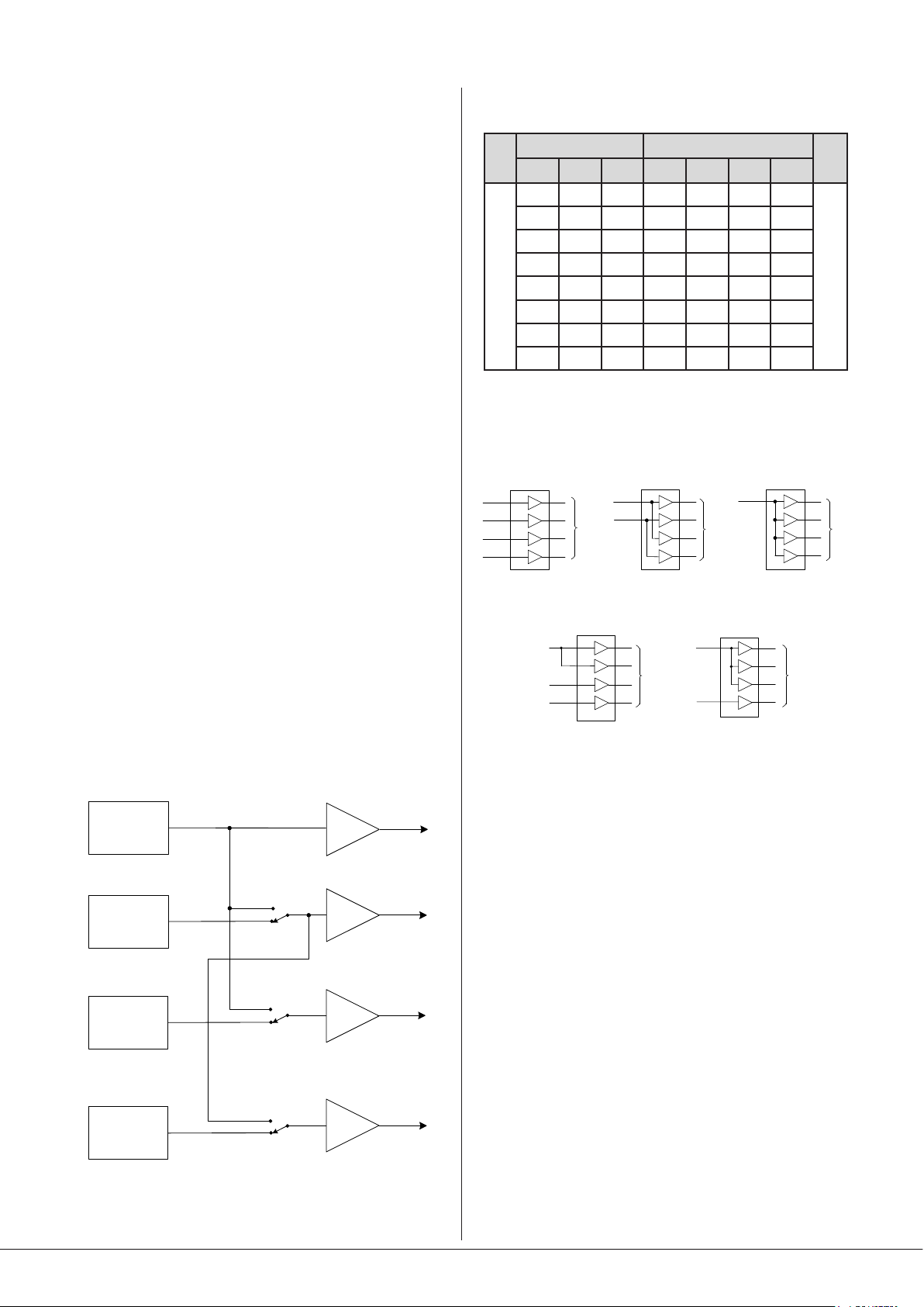
Zone Routing (using output stages in parallel)
In some installations, a higher power output may be required
in a zone than the 80 W the 46-80’s power stages are rated
at. To meet this requirement, the power stages may have
their inputs recongured so that two or more may be fed by
a single pre-amplier stage. For example, the power stages
for Zones 1 and 2 may be both fed by Zone 1’s preamplier
stage: in this case, the front panel Zone 1 controls will affect
both Zone Speaker Outputs, and the Zone 2 controls will
be non-operational. (Clearly, using this option reduces the
overall number of zone outputs available.)
The alternative Zone routings are selected by moving internal
PCB jumpers J7, J8 and J9 in various combinations. See page
30 for locations of PCB jumpers. The diagram below
summarises the jumpers’ effects:
The table below shows all the routing congurations available
from the eight possible combinations of jumper settings:
JUMPER AMP CHANNEL
J7 J8 J9 CH1 CH2 CH3 CH4
D D D Z1 Z2 Z3 Z4
R D D Z1 Z1 Z3 Z4
INPUT ZONE
D R D Z1 Z2 Z1 Z4
R R D Z1 Z1 Z1 Z4
D D R Z1 Z2 Z3 Z2
R D R Z1 Z1 Z3 Z1
D R R Z1 Z2 Z1 Z2
R=REROUTED = DEFAULT
R R R Z1 Z1 Z1 Z1
The diagram below illustrates some useful congurations
with the necessary jumper settings:
STAGES
TO POWER
1 x MONO
J7 = R
J8 = R
J9 = D
4 x MONO PARALLEL
IN 1
J7 = R
J8 = R
J9 = R
STAGES
TO POWER
TO POWER
4 X MONO CHANNELS
IN 1
IN 2
IN 3
IN 4
J7 = D
J8 = D
J9 = D
IN 1
IN 2
STAGES
TO POWER
IN 1
IN 3
IN 4
2 x MONO CHANNELS
+ 2 PARALLELED CHANNELS
J7 = R
J8 = D
J9 = D
2 x STEREO
J7 = D
J8 = R
J9 = R
STAGES
TO POWER
IN 1
IN 4
+ 3 x PARALLELED CHANNELS
STAGES
Zone 1 pre-amp
Zone 2 pre-amp
Zone 3 pre-amp
Zone 4 pre-amp
24
Z1
J7
REROUTE
DEFAULT
REROUTE
DEFAULT
REROUTE
DEFAULT
J8
J9
Z2
Z3
Z4
POWER
AMPLIFIER
STAGES
46-80 Installation and User Guide V1.0
Utility/Loop Output
The UTILITY/LOOP OUTPUT ([17] on page 13) is primarily
intended to drive an external hearing loop amplier, though
as a balanced line level output, it may be used for any purpose
required by the audio system.
Eight source options are available for the music component
of the signal at the Utility/Loop output, and is selected by
rear panel DIP switches SW3/6, SW3/7 and SW3/8 (UTILITY
SOURCE A, B and C respectively). The options are:
• The Utility/Loop output always follows the music source
selection made for any of the four Zones (either on the
front panel or via remote control). The MUSIC LEVEL
control for the selected Zone does not affect the level at
the Utility/Loop output. If Line 6 Priority is enabled for the
selected Zone, its effect will also be heard via the Utility/
Loop output, ensuring that e.g., emergency messages will
always be heard via the hearing loop. However, music will
not be ducked by Mic-over-Music priority, if it is enabled.
• The Utility/Loop output always follows the source
connected to LINE IN 1.
Page 25
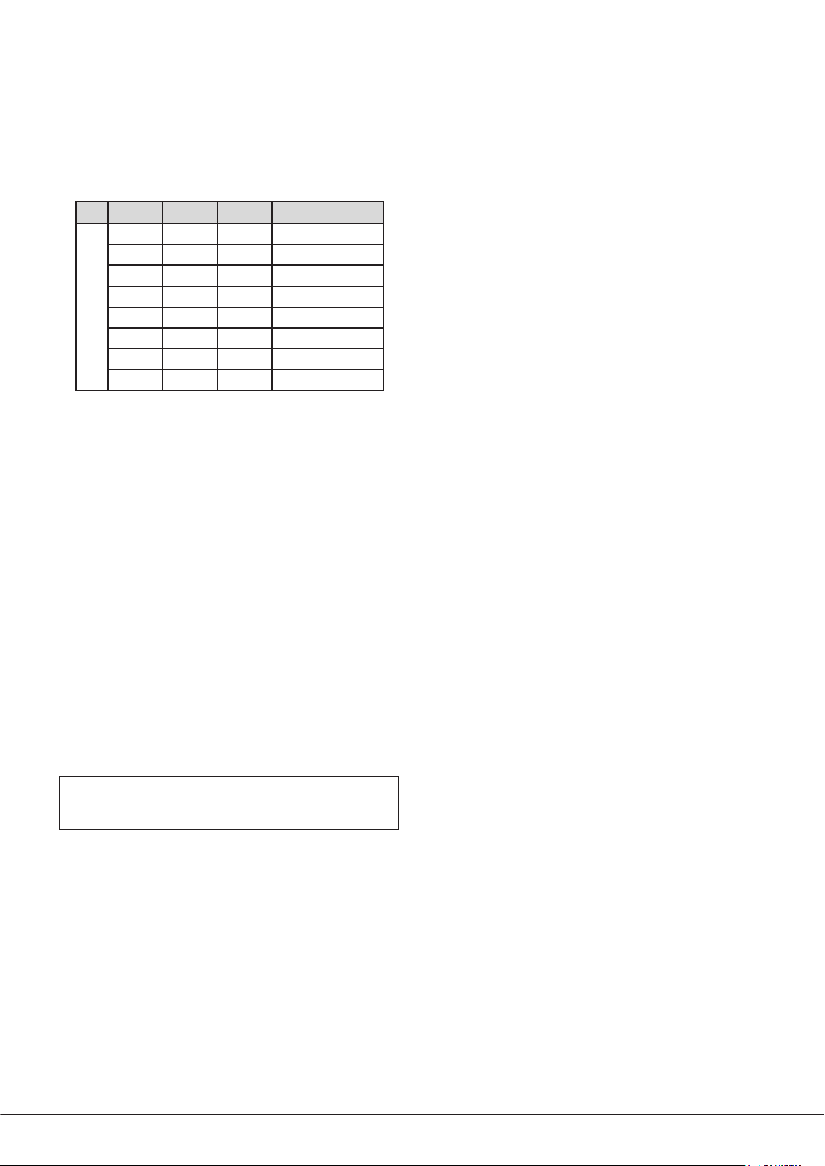
• The Utility/Loop output always follows the source
connected to LINE IN 6: this option is useful if Line 6 Priority
is enabled for emergency messages, but there are building
areas which need not be fed with music. The output will
only carry the Line In 6 source when it is active.
Selection of music source is made by the following table; 0 =
switch up, 1 = switch down:
SW3/6 SW3/7 SW3/8 MUSIC SOURCE
0 0 0 ZONE 1
0 0 1 ZONE 2
0 1 0 ZONE 3
0 1 1 ZONE 4
1 0 0 LINE 1
1 0 1 LINE 6
DIP SWITCHES
1 1 0 ZONE 1
1 1 1 ZONE 1
The music level at the Utility/Loop output can be adjusted by
the adjacent MUSIC preset control. The signal is effectively
‘off’ with the preset control in its fully anticlockwise position.
The music signal selected for the Utility/Loop output is mixed
with a sum of the microphone signals at Mic Input 1 and Mic
Input 2, and derived from the Zone 1 preamplier stage. This
applies whether a mic is connected to the MICROPHONE
1/PAGE MIC connector or to the DIGITAL PAGE MIC port,
and ensures that if Mic 1 Input is congured for paging,
announcements intended for Zone 1 will be heard via the
Utility/Loop output regardless of music source selection.
Auto Power Down
The 46-80 is an extremely energy-efcient mixer-amplier,
but can be made even more so by enabling the Auto PowerDown feature. When active, the signal level is constantly
monitored and if no input signals are measured for either 15
or 30 minutes (selectable), the unit enters a “Sleep” mode,
minimising power consumption. If an input signal is detected
while in Sleep Mode, the mixer-amplier “wakes up” in less
than 450 ms: if the signal is a line input, the volume will be
faded up over a period of three seconds.
The 46-80 is shipped with the Auto Power Down function
disabled. It may be enabled by setting rear panel DIP switch
SW3/1 (APD ON) to ON (switch down). Switch SW3/2 (APD
TIMING) is set to 15M by default, giving a 15 minute delay
before entering Sleep Mode: this may be increased to 30
minutes by setting SW3/2 to 30M (switch down).
The level of the mic signal is adjusted with the adjacent MIC
preset control. The signal is effectively ‘off’ with the preset
control in its fully anticlockwise position. Note that the music
content of the signal at the output is NOT altered by Zone
1’s front panel MUSIC LEVEL control or MUSIC EQ preset
adjustments, but the mic content will be varied by Zone 1’s
MIC 1 and MIC 2 LEVEL controls.
Note that mic or music sources from a remote input module
connected to the Facility Port are not routed to the Utility/
Loop Output.
IMPORTANT: The UTILITY/LOOP output is NOT affected
by the MUSIC MUTE input.
Auxiliary Outputs
The two AUX OUT connectors will always carry the signal at
the outputs of the preamplier sections for Zone 1 and Zone
2. Thus the effects of muting, priorities, etc., active in these
Zones will be reected at the auxiliary outputs.
Note also the sources for the Auxiliary Outputs are derived
“post” the front panel MUSIC LEVEL and MIC LEVEL controls,
and will therefore be controlled by them, or any remote
control plates connected to those Zones.
46-80 Installation and User Guide V1.0
25
Page 26

46-80 SERIAL CONTROL
The 46-80 is equipped with a bi-directional RS-232 serial
interface.
As a receiver, the interface permits external control of certain
46-80 settings. These are:
• Music Source selection in each zone
• Music level control in each zone
• MIC 1 muting in each zone
• Global MIC 2 muting (all zones)
MIC1
MUSIC
LEVEL
/MUTE
MIC2
VCA
MUTE
MIC1
ZONES 1-4
80W
70/100V
LINE TX
(OPTION)
ZONE 1
ZONE 2
OUT
ZONE 3
ZONE 4
MUTE MIC2 (ALL ZONES)
RS232
LINE1
LINE6
SOURCE
MUSIC
SOURCES
MUSIC
SELECT
The 46-80 appears as a DCE (Data Communications
Equipment) device to controlling equipment. As the
controlling device will probably be congured as a DTE device,
this requires the use of a straight (uncrossed) cable with the
Tx (Data Transmit) pins at the cable ends connected to each
other and the Rx pins (Data Receive) similarly connected to
each other.
Abridged command set
The commands listed in the table below are some of those
most commonly required when controlling a 46-80 from an
AV control system. For all other commands, data requests
and responses, please refer to the 46-80’s full RS-232
protocol document.
GENERAL FORMAT
FUNCTION COMMAND (ASCII)
Route Line Input x to Zone y
Set music level in
Zone y to –m dB
Reduce music level in
Zone y by p dB
Increase music level in
Zone y by q dB
Mute Mic x
Unmute Mic x
Access paging in Zone y
(see Example 4)
Release paging
Examples:
1. Music source selection:
The values of x and y in the general format are the Line
Input No. (1 to 6) and the Zone No. (1 to 4) respectively.
<Zy.MU,Sx/>
<Zy.MU,Lm/>
<Zy.MU,LDp/>
<Zy.MU,LUq/>
<Mx,M/>
<Mx,O/>
<M1,PAy/>
<M1,PR/>
parameter VALUE/SETTING
Data type: RS-232 serial
Data speed 9600 baud*
Word length 8 bits
Parity None
Stop bits One
*The default baud rate of 9600 baud may be altered by sending the
appropriate RS-232 commands; details are in the RS-232 protocol document.
The full RS-232 protocol is beyond the scope of this manual,
but is available for download from www.cloud.co.uk.
This section provides only serial port details and an abridged
serial command list.
EXAMPLE COMMAND (ASCII) COMMAND (HEX)
Select Input
3 in Zone 2
<Z2.MU,S3/>
3C 5A 32 2E 4D 55
2C 53 33 2F 3E
2. Music levels:
Levels can either be set in a specied zone to an absolute
value (in dBs), or increased/decreased by a specied number
of dBs. Either may be dened in steps of 1 dB.
For absolute levels, the number of dBs corresponds to
attenuation rather than gain, thus 0 dB is maximum level and
at -90 dB the zone is muted. The values of y in the general
format is the Zone No. (1 to 4) and m is the attenuation level
in one-dB steps (0 to 90) respectively.
To alter the Zone level by a specied amount, the additional
ASCII characters ‘U’ (up) or ‘D’ (down) are added to the string.
The values of y, p and q in the general format are the Zone
No. (1 to 4), the level increase in one-dB steps (0 to 90), or
the level decrease in one-dB steps (0 to 90) respectively. A
command to increment the level by a number of dBs greater
than the current attenuation will set the level to maximum.
Similarly, a command that would decrement the level below
90 dB attenuation will mute the Zone output.
26
46-80 Installation and User Guide V1.0
Page 27
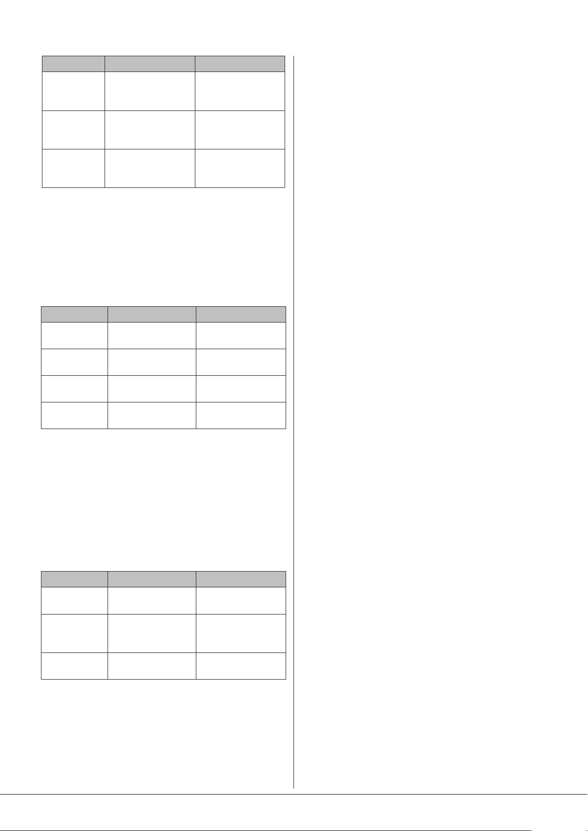
EXAMPLE COMMAND (ASCII) COMMAND (HEX)
Set level in
Zone 2
to -12 dB
Reduce level
in Zone 1
by 10 dB
Increase level
in Zone 4
by 6 dB
<Z2.MU,L12/>
<Z1.MU,LD10/>
<Z5.MU,LU6/>
3C 5A 32 2E 4D 55
2C 4C 31 32 2F 3E
3C 5A 31 2E 4D 55
2C 4C 44 31 30 2F
3E
3C 5A 34 2E 4D 55
2C 4C 55 36 2F 3E
3. Mute/Unmute Mics
Either of the 46-80’s two mic inputs may be enabled or
disabled. This may be done on a per-zone basis for Mic Input
1, and globally (all zones) for Mic Input 2.
The value of x in the general format is the Mic input (1 or 2).
EXAMPLE COMMAND (ASCII) COMMAND (HEX)
Mute Mic 1 in
Zone 2 only
Unmute Mic 1
in Zone 2 only
Mute Mic 2
globally
Unmute Mic 1
globally
<Z2.M1,M/>
<Z2.M1,O/>
<M2,M/>
<M1,O/>
3C 5A 32 2E 4D 31
2C 4D 2F 3E
3C 5A 32 2E 4D 31
2C 4F 2F 3E
3C 4D 32 2C 4D 2F
3E
3C 4D 31 2C 4F 2F
3E
4. Enable/Release Paging
RS-232 control of paging allows an audio signal connected at
MIC 1 to be routed for paging.
This command differs from the others in that the value of
y in the general format is in the form of a 4-character mask
of ASCII “X’s” (select) and “O’s” (don’t select), with the
character position in the mask denoting the Zone number.
EXAMPLE COMMAND (ASCII) COMMAND (HEX)
Access paging
for Zone 3
Access paging
for Zones 1
and 4
Release
paging
Note that it is not strictly necessary to transmit the “O”
character (4Fh) for channel numbers above the highest being
paged. Thus <PM,PAOOX/> (ASCII) would sufce in the rst
example above. However, the full four characters are shown
in the table for completeness, with the extra character in
brackets in the hex version.
<PM,PAOOXO/>
<PM,PAXOOX/>
<PM,PR/>
3C 50 4D 2C 50 41
4F 4F 58 (4F) 2F 3E
3C 50 4D 2C 50 41
4F 4F 4F 58 2F 3E
3C 50 4D 2C 50 52
2F 3E
46-80 Installation and User Guide V1.0
27
Page 28

OPTIONS AND ADDITIONAL INFORMATION
RL-1 and RSL-6 Series remote control plates – general considerations
Cloud RL-1 Series and RSL-6 Series remote control plates
are available in two form factors, to t single-gang UK or
American electrical back boxes. Back boxes of either the
recessed type or surface-mounting type may be used,
providing they are at least 25 mm deep.
The plates should be connected to the REMOTE MUSIC
CONTROL port of the relevant zone using single- or twincore screened cable as described on page 18. The plate
terminations are conventional screw terminals and the
remote MUSIC CONTROL port on the mixer is a 3-pin 5 mmpitch screw terminal connector.
The remote control plates are passive and thus do not draw
any current from the mixer.
Control of music source and level via external DC
It may be necessary in some installations to adjust the music
level and select music source in one or more zones from an
external AV control system. If the REMOTE MUSIC CONTROL
ports are not required for RL-1/RSL-6 Series remote control
plates, they may be used to receive DC voltages from the
external system to effect these adjustments.
Both music source selection and level can be controlled over
their full ranges with a DC voltage of 0 to +10 V. The pinout
of the REMOTE MUSIC CONTROL port is as follows:
PIN USE
1 0 V ref.
2 Music level control (0 to +10 V)
3 Music source selection (0 to +10 V)
minimise this risk, we suggest that all pieces of equipment be
in close proximity, and supplied from the same power outlet.
Music level
Music level in a zone may be varied over its full range by
applying a DC voltage of between 0 V and +10 V to pin 2,
the 0 V reference being connected to Pin 1. 0 V on pin 2
corresponds to maximum level and +10 V will produce
60 dB of attenuation. The rate of attenuation is approximately
165 mV/dB.
Note that there is an internal 4k7 “pull-up” resistor between
pin 2 and the internal +12 V rail. If pin 2 is left “oating”, this
pull-up will result in full attenuation. The output impedance
of the control voltage source should be low enough to
overcome the effect of this resistor.
Music source
Music source for a zone may be controlled by applying
various DC voltages of between 0 and +10 V to pin 3, the
0 V reference being connected to pin 1. 0 V at pin 3 will select
Line input 6 and between +6 V and +7.2 V will select Line
input 1. The other line inputs will be selected with intermediate
voltages. Taking pin 3 above +7.2 V will deselect all inputs,
making the zone effectively ‘off’ for music.
The table below lists the DC voltages required at pin 3 to
select each line input. The third column is the value of a
resistor which should be connected between pins 1 and 3 to
permanently ‘force’ a zone to a particular line input.
INPUT DC VOLTAGE RESISTOR VALUE
OFF >+7.2 V Open-circuit
Line 1 +6.0 V 16k
Line 2 +4.8 V 10k
Line 3 +3.6 V 6k8
Line 4 +2.4 V 3k9
Line 5 +1.2 V 1k8
Line 6 0 V short-circuit
CONTROL
SYSTEM
SOURCE CONTROL
LEVEL CONTROL
0 V REF
REMOTE
PORT
SOURCE+LEVEL
+12 V
4k7
15k
3
2
1
0 V
46-80
MUSIC SOURCE
SELECT
MUSIC VCA
NOTE: If the control voltage source is not isolated from the
power earth, there is a small risk of creating a ‘ground loop’
by linking the mixer technical ground (0 V) to the ground
(0 V) of the equipment supplying the control voltages. To
28
46-80 Installation and User Guide V1.0
Note that there is an internal 15k “pull-up” resistor between
pin 3 and the internal +12 V rail. If pin 3 is left “oating”, this
pull-up will cause ‘OFF’ to be selected. The output impedance
of the control voltage source should be low enough to
overcome the effect of this resistor.
Page 29

Using the Facility Port as an auxiliary zone input
The Facility Port provides a balanced audio input to Zone 1. If
the port is not connected to an active remote module, it may
be used as a direct input to Zone 1 from other equipment
forming part of the system (for example, a permanently
installed DJ mixer which only ever needs to route its output
to Zone 1).
Wire an external balanced source to the facility port as
shown below:
BALANCED
2
hot (+)
3
1
cold (-)
ZONE 1 FACILITY PORT
(RJ45)
hot (+)
cold (-)
1
2
3
4
5
6
7
8
OUTPUT (e.g. XLR)
An unbalanced source may also be connected; the use of
balancing transformers is recommended.
Fitting CXL-80T transformers
NOTE: Full installation instructions are
included with the transformer.
The notes below are an abridged version.
The CXL-80T transformer allows Model 46-80 to be used
with 70/100 V-line loudspeaker systems. One transformer
will be needed for each Zone output to be congured for
70/100 V-line operation.
1. Disconnect the 46-80 from the mains and remove the
top cover.
2. With the rear panel facing you, t the transformers
to the right-hand chassis side using the M4 x 45 bolts
supplied. Four M4 holes are provided in the side panel
for this purpose.
3. Each transformer terminates in one 2-pin and one 3-pin
connector. The 2-pin one (black/red) is the input, the
3-pin one (blue/purple/white) is the output.
4. Identify the power amplier section feeding the Zone
Output to be converted: this is easily done by tracing
the blue/white twisted pairs back from the SPEAKER
OUTPUT connector. Unplug both ends of the twisted
pair and remove
5. Plug the 2-pin connector from the transformer into the
header on the power amplier board now vacated.
6. Plug the other connector from the transformer onto
the corresponding 3-pin header behind the SPEAKER
OUTPUT connector. There are two per Zone Output:
those nearer the rear panel are for 100 V-line operation,
the other set is for 70 V-line operation.
7. Enable the 65 Hz high-pass lters for the relevant
channels (J3, J4, J5 & J6). See page 30 for jumper
locations.
8. Replace the cover.
9. Do not re-power the 46-80 until the external speaker
connections have been made and the safety cover
retted over the SPEAKER OUTPUT connector.After
connecting the 70/100 V-line loudspeaker system (see
page 20), t the blanking plate from Step 2 onto the
hex spacers (Step 8) over the connector, with the printed
warnings outwards.
46-80 Installation and User Guide V1.0
29
Page 30

APPENDIX
PCB jumper locations
The 46-80 has various internal jumpers, the setting of which may require alteration during installation. The diagram below
shows the locations of the internal jumpers (not to scale) on the internal PCBs, and the table below lists each jumper and its
purpose, together with the factory default setting.
Note that the 46-80 has several PCBs. One of these, the upper PCB (mounted inside the rear panel) carries two jumpers (J1 and
J2), but all other jumpers are on the main PCB.
All “user” jumpers have two possible positions; the black square in the symbol on the diagram below indicates the default
setting. If any jumpers need to be changed, turn the 46-80 off and disconnect it from the mains. Undo the eight screws securing
the top cover of the unit and remove it. Use a pair of small pliers to gently remove the jumpers from the PCB headers and
reposition them as required. Ret the top cover using the same screws.
The PCB diagram (which is as viewed from the rear of the unit) also shows the locations of the headers relevant to retrotting
one or more CXL-80T transformers (see page 29).
Power module output
headers – Z1 & Z2
TO FRONT PANEL PCB
J3
J4
J6
J5
J7
J8
J9
Power module output
headers – Z3 & Z4
POWER MODULE – Z1 & Z2
Z2 Z1
Z4 Z3
POWER MODULE – Z3 & Z4
J11
J10
30
UPPER PCB
46-80 Installation and User Guide V1.0
J12
J13
MAIN PCB
Output connectors for
70 V-line operation
Z1 Z2 Z3 Z4
J1
J2
Output connectors for
Lo-Z or 100 V-line operation
Page 31

Table of internal jumpers and default settings
The table below lists each jumper and its purpose, together with location and factory default setting.
JUMPER PCB DESCRIPTION EFFECT DEFAULT
J1 Upper CDPM bus termination
J2 Upper Mic-over-Facility port priority
J3 Main Zone 1 65 Hz High Pass Filter
J4 Main Zone 2 65 Hz High Pass Filter
J5 Main Zone 3 65 Hz High Pass Filter
J6 Main Zone 4 65 Hz High Pass Filter
J7 Main Power amp Z2 input source
J8 Main Power amp 32 input source
J9 Main Power amp Z4 input source
ALWAYS ON – DO NOT MOVE
OFF: Mic signals will be mixed at full level with Facility Port input
ON: An input at Mic 1 or Mic 2 will cause a signal from the
Facility Port to duck
OFF: full frequency response
ON: 65 Hz hi-pass lter enabled for Zone 1
OFF: full frequency response
ON: 65 Hz hi-pass lter enabled for Zone 2
OFF: full frequency response
ON: 65 Hz hi-pass lter enabled for Zone 3
OFF: full frequency response
ON: 65 Hz hi-pass lter enabled for Zone 4
D: Power amp Z2 is fed from Z2 pre-amp
R: Power amp Z2 is fed from Z1 pre-amp
D: Power amp Z3 is fed from Z3 pre-amp
R: Power amp Z3 is fed from Z1 pre-amp
D: Power amp Z4 is fed from Z4 pre-amp
R: Power amp Z4 is fed with source selected by J7
ON
OFF
OFF*
OFF*
OFF*
OFF*
D
D
D
J10 Main APD Test Mode
J11 Main NVM Reset Restores factory settings
J12 Main Spare
J13 Main Programming header
*These jumpers are factory-set to ON in Model 46-80T.
FOR FACTORY USE ONLY - DO NOT FIT A JUMPER
FOR FACTORY USE ONLY - DO NOT FIT A JUMPER
FOR FACTORY USE ONLY - DO NOT FIT A JUMPER
Restoring factory settings
If it is necessary to restore the 46-80’s settings to their original factory defaults, temporarily t a jumper to the J11 header and
power-cycle the unit. Remove the temporary jumper before replacing the lid.
46-80 Installation and User Guide V1.0
31
Page 32
Summary of rear panel DIP switch functions
(Factory default settings are in BOLD text.)
DIP SWITCH SW1 POSITION FUNCTION
1
2
3
MIC 1
PHANTOM
POWER
MIC 2
PHANTOM
POWER
MIC OVER
MUSIC
OFF = MIC 1 PHANTOM POWER OFF No phantom power at MICROPHONE 1 / PAGE MIC input.
OFF = MIC 1 PHANTOM POWER ON
OFF = MIC 2 PHANTOM POWER OFF No phantom power at MICROPHONE 2 input.
OFF = MIC 2 PHANTOM POWER ON
OFF = NO PRIORITY
OFF = PRIORITY ON Music ducks when either mic is in use
15 V phantom power available at MICROPHONE 1 / PAGE MIC input.
15 V phantom power available at MICROPHONE 2 input.
No priority – both mics mix with music
MUTE – N/O
4
OR N/C
PAGING
5
MODE
DIP SWITCH SW2 POSITION FUNCTION
1 Z1 LEVEL
2 Z1 SOURCE
3 Z2 LEVEL
4 Z2 SOURCE
5 Z3 LEVEL
6 Z3 SOURCE
7 Z4 LEVEL
8 Z4 SOURCE
N/O = NORMALLY OPEN CONTACTS
N/C = NORMALLY CLOSED CONTACTS External contact opening required for muting
MIC = MIC MODE
PG = PAGE MODE
LOC = LOCAL CONTROL OF Z1 MUSIC LEVEL
REM = REMOTE CONTROL OF Z1 MUSIC LEVEL
LOC = LOCAL SELECTION OF Z1 MUSIC SOURCE
REM = REMOTE SELECTION OF Z1 MUSIC SOURCE
LOC = LOCAL CONTROL OF Z2 MUSIC LEVEL
REM = REMOTE CONTROL OF Z2 MUSIC LEVEL
LOC = LOCAL SELECTION OF Z2 MUSIC SOURCE
REM = REMOTE SELECTION OF Z2 MUSIC SOURCE
LOC = LOCAL CONTROL OF Z3 MUSIC LEVEL
REM = REMOTE CONTROL OF Z3 MUSIC LEVEL
LOC = LOCAL SELECTION OF Z3 MUSIC SOURCE
REM = REMOTE SELECTION OF Z3 MUSIC SOURCE
LOC = LOCAL CONTROL OF Z4 MUSIC LEVEL
REM = REMOTE CONTROL OF Z4 MUSIC LEVEL
LOC = LOCAL SELECTION OF Z4 MUSIC SOURCE
REM = REMOTE SELECTION OF Z4 MUSIC SOURCE
External contact closure required for muting
Both Mic Inputs function as standard microphone inputs, including GAIN
and LEVEL controls.
Mic 1 input functions as a typical Cloud paging input: connect a paging
mic to either the MICROPHONE 1 / PAGE MIC input (select zones using
the MIC 1 ACCESS port), or via the DIGITAL PAGE MIC port.
Music level in Zone 1 is set by the front panel ZONE 1 MUSIC LEVEL
control.
Music level in Zone 1 is controlled by a remote plate/module connected
to the REMOTE MUSIC CONTROL port (ZONE 1), or via RS232
commands.
Music source in Zone 1 (Line 1 to Line 6) is selected by the front panel
ZONE 1 MUSIC SOURCE control.
Music source in Zone 1 (Line 1 to Line 6) is selected on a remote plate/
module connected to the REMOTE MUSIC CONTROL port (ZONE 1), or
via RS232 commands.
Music level in Zone 2 is set by the front panel ZONE 2 MUSIC LEVEL
control.
Music level in Zone 2 is controlled by a remote plate/module connected
to the REMOTE MUSIC CONTROL port (ZONE 2), or via RS232
commands.
Music source in Zone 2 (Line 1 to Line 6) is selected by the front panel
ZONE 2 MUSIC SOURCE control.
Music source in Zone 2 (Line 1 to Line 6) is selected on a remote plate/
module connected to the REMOTE MUSIC CONTROL port (ZONE 2), or
via RS232 commands.
Music level in Zone 3 is set by the front panel ZONE 3 MUSIC LEVEL
control.
Music level in Zone 3 is controlled by a remote plate/module connected
to the REMOTE MUSIC CONTROL port (ZONE 3), or via RS232
commands.
Music source in Zone 3 (Line 1 to Line 6) is selected by the front panel
ZONE 3 MUSIC SOURCE control.
Music source in Zone 3 (Line 1 to Line 6) is selected on a remote plate/
module connected to the REMOTE MUSIC CONTROL port (ZONE 3), or
via RS232 commands.
Music level in Zone 4 is set by the front panel ZONE 4 MUSIC LEVEL
control.
Music level in Zone 4 is controlled by a remote plate/module connected
to the REMOTE MUSIC CONTROL port (ZONE 4), or via RS232
commands.
Music source in Zone 4 (Line 1 to Line 6) is selected by the front panel
ZONE 4 MUSIC SOURCE control.
Music source in Zone 4 (Line 1 to Line 6) is selected on a remote plate/
module connected to the REMOTE MUSIC CONTROL port (ZONE 4), or
via RS232 commands.
32
46-80 Installation and User Guide V1.0
Page 33
DIP SWITCH SW3 POSITION FUNCTION
1 APD ON
2 APD TIMING
LINE 6
3
PRIORITY Z1
LINE 6
4
PRIORITY ALL
5 (UNUSED)
UTILITY
6
SOURCE A
UTILITY
SOURCE B
UTILITY
9
SOURCE C
OFF = APD MODE OFF
ON = APD MODE ENABLED
15M = 15 MINS DELAY
30M = 30 MINS DELAY
OFF = PRIORITY OFF
ON = PRIORITY ON
OFF = PRIORITY OFF
ON = PRIORITY ON
These switches are used in combination to select the
music source for the UTILITY/LOOP output. Options
are: Zones 1 to 4, Line 1 or Line 6.
46-80 remains in Active Mode unless unpowered.
46-80 will enter Sleep Mode if no input signals are detected for the
period set by SW3/2.
If SW3/1 is set to ON, 46-80 will enter Sleep Mode if no input signals are
detected for 15 minutes.
If SW3/1 is set to ON, 46-80 will enter Sleep Mode if no input signals are
detected for 30 minutes.
Music Source in Zone 1 will always be that selected by the front panel
ZONE 1 MUSIC SOURCE control (SW2/2 = LOC), or by a remote control
plate/module connected to the REMOTE MUSIC CONTROL port (ZONE
1), or via RS232 commands (SW2/2 = REM).
A signal applied to Line Input 6 will automatically replace the current
music source selection for Zone 1.
Music Source in all Zones will always be that selected by the respective
front panel MUSIC SOURCE controls (SW2/2, 4, 6 or 8 = LOC), or by
a remote control plate/module connected to the REMOTE MUSIC
CONTROL port, or via RS232 commands (SW2/2, 4, 6 or 8 = REM).
A signal applied to Line Input 6 will automatically replace the current
music source selection in all Zones.
Refer to Music Source selection table at Page 25 (also on lid of unit).7
EMC considerations
The Cloud 46-80 fully conforms to the relevant electromagnetic compatibility (EMC) standards and is technically well behaved;
you should experience no operational problems and under normal circumstances, no special precautions need to be taken. If
the unit is to be used within close proximity to potential sources of HF disturbance such as high power communications
transmitters, radar stations and the like, the performance of the mixer may be reduced; we suggest that all microphone and
line input cables are kept as short as possible.
Ground loops
If, despite your best efforts, the completed sound system ‘hums’ you probably have a ‘ground loop’. The offending signal
source can often be identied by setting the volume control to minimum, then disconnecting the input leads (both left & right
channels) on each line input until the ‘hum’ disappears. This problem is often caused by terminating a screened input cable into
a signal source positioned a signicant distance from the mixer. A good way of avoiding this potential problem is to use signal
sources (typically ‘consumer’ equipment) that are double insulated with no connection to the mains supply earth. If a signal
feed were derived from a second mixer (a club or microphone mixer for example) it would be perfectly normal to expect this
to be earthed; we suggest that a transformer be used to isolate the signal and prevent a noisy loop (see page 15).
46-80 Installation and User Guide V1.0
33
Page 34
TECHNICAL SPECIFICATIONS
Technical specications
Line Inputs 1 & 2 (unbalanced)
Frequency Response ±0.5 dB, 20 Hz to 20 kHz
THD + N <0.02%, 1 kHz sine wave
Sensitivity 195 mV (-12 dBu) to 2.0 V (+8 dBu)
Gain control range -10 dB to +10 dB
Input Impedance 10.2 kohms
Headroom 17 dB
Noise <-88.5 dB (nominal gain, max level, 22 Hz to 22 kHz)
Line Inputs 3 to 6 (balanced)
Frequency Response -0.5 dB @ 20 Hz; -0.5 dB @ 20 kHz
THD + N <0.015%, 1 kHz sine wave
Sensitivity 195 mV (-12 dBu) to 2.0 V (+8 dBu)
Gain control range -9 dB to +11 dB
Input Impedance 10.2 kohms
Headroom 17 dB
Noise <-88.5 dB (nominal gain, max level, 22 Hz to 22 kHz)
Microphone Inputs
Frequency Response -6 dB @100 Hz (xed lter) to ±1 dB @ 20 kHz
THD + N <0.05%, 1 kHz sine wave
Gain Range 10 dB to 48 dB
Common mode rejection <58 dB @ 1 kHz
Input Impedance 3.3 kohms (balanced)
Headroom 18 dB
Noise (EIN) -127.2 dB; 22 Hz to 22 kHz, maximum gain, Rs = 150 ohms
Phantom Power 15 V, individually selectable
Equalisation HF: ±10 dB @ 5 kHz; LF: ±10 dB @ 100 Hz
Main Outputs
Low Impedance Outputs (Model 46-80) 80 W into 4 ohms
High Impedance Outputs
(Model 46-80T)
Amplier protection
100 V operation 80 W constant voltage into 125 ohm minimum load
70 V operation 70.7 W constant voltage into 62.5 ohm minimum load
Fixed level signal limiter, protection against DC, over current, over
temperature
Cooling Natural convection
Utility/loop Output
Frequency Response ±0.5 dB, 20 Hz to 20 kHz
THD + N <0.01% @ 1 kHz
Nominal level 0 dBu (0.775 Vrms)
Aux Outputs (Zones 1 & 2)
Frequency Response ±0.5 dB, 20 Hz to 20 kHz
THD + N <0.05% @ 1 kHz
Nominal level 0 dBu balanced (0.775 Vrms)
34
46-80 Installation and User Guide V1.0
Page 35
General
Power input 85 to 243 VAC, 47 to 63 Hz
Normal operating temperature
Power consumption
0 °C to 35 °C (Note: performance and specications cannot be guaranteed
outside of this range)
Standby
Idle
1/8th Power
1/3rd Power
Standby
Idle
1
2
3
8.6 W, 27.5 VA
20.3 W, 38.6 VA
Lo-Z output (4 ohms): 64.9 W, 85.2 VA
Hi-Z output (100 V into 125 ohms): 92 W, 109.7 VA
4
Lo-Z output (4 ohms): 126 W, 154 VA
Hi-Z output (100 V into 125 ohms): 176 W, 198 VA
1
2
30.8 kJ/hr (29 BTU/hr)
72 kJ/hr (69 BTU/hr)
Lo-Z output (4 ohms): 103 kJ/hr (98 BTU/hr)
3
Hi-Z output (100 V into 125 ohms): 187 kJ/hr
(177 BTU/hr)
Heat Loss
1/8th Power
Lo-Z output (4 ohms): 129 kJ/hr (122 BTU/hr)
1/3rd Power
4
Hi-Z output (100 V into 125 ohms): 287 kJ/hr
(272 BTU/hr)
Net
482.6 mm x 88 mm (2U) x 320 mm
19” x 3.5” x 12.6”
Dimensions
Shipping (Gross)
Net
Weights
Shipping (Gross)
610 mm x 200 mm x 460 mm
24” x 8” x 18”
46-80: 5.5 kg / 12.3 lbs
46-80T: 8.6 kg / 19.3 lbs
46-80: 8 kg / 17.9 lbs
46-80T: 11.1 kg / 24.9 lbs
Notes re Power Consumption and Heat Loss measurements:
All measurements at 230 VAC 50 Hz power input
1. Standby: amplier in standby state (STATUS LED steady red)
2. Idle: amplier not in standby state (STATUS LED steady green), but no audio output
3. 1/8th. Power: constant sound level at 10 W output (audio mainly clean, only occasional clipping)
4. 1/3rd. Power: constant sound level at 27 W output (audio beginning to become compressed, limited or heavily clipped)
46-80 Installation and User Guide V1.0
35
Page 36

www.cloud.co.uk
www.cloudusa.pro
 Loading...