

Page 1
46-50 Installation and User Guide V1.0
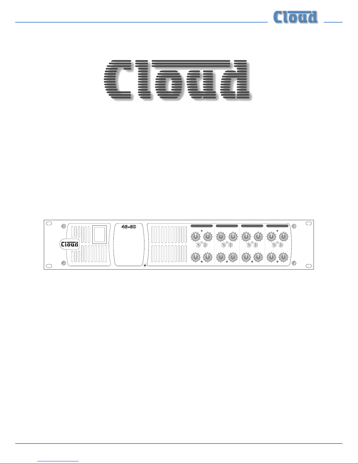
46-50 FOUR ZONE
INTEGRATED
MIXER AMPLIFIER
Installation and User Guide
0
1
SOURCESOURCESOURCESOURCE
MUSIC LEVELMUSIC LEVELMUSIC LEVELMUSIC LEVEL
MIC 2
MIC 1
LEVEL
1
2
3
4
5
6
HFLF
0
1010
10
0
-
dB
ZONE 1 MUSIC EQ
CLIP
MIC 2
MIC 1
LEVEL
1
2
3
4
5
6
HFLF
0
1010
10
0
-
dB
ZONE 2 MUSIC EQ
CLIP
MIC 2
MIC 1
LEVEL
1
2
3
4
5
6
HFLF
0
1010
10
0
-
dB
ZONE 2 MUSIC EQ
CLIP
MIC 2
MIC 1
LEVEL
1
2
3
4
5
6
HFLF
0
1010
10
0
-
dB
ZONE 2 MUSIC EQ
CLIP
ZONE 1 ZONE 2 ZONE 3 ZONE 4
4 ZONE 50W INTEGRATED
MIXER AMPLIFIER
Page 2
46-50 Installation and User Guide V1.0
2
WARNING:
To reduce the risk of re or electric shock, do not expose this appliance to rain or moisture.
CAUTION:
Use of controls or adjustments or performance of procedures other than those specied may result in hazardous radiation
exposure.
WARNING: SHOCK HAZARD – DO NOT OPEN
AVIS: RISQUE DE CHOC ELECTRIQUE – NE PAS OUVRIR
The lightning ash with the arrowhead symbol within an equilateral
triangle, is intended to alert you to the presence of uninsulated
dangerous voltages within the product’s enclosure that may be of
sufcient magnitude to constitute a risk of electric shock.
The exclamation point within an equilateral triangle is intended to
alert the user to the presence of important operating and maintenance
(servicing) instructions in the literature accompanying the appliance.
Page 3
46-50 Installation and User Guide V1.0
3
IMPORTANT SAFETY INSTRUCTIONS
1. Read these Instructions.
2. Keep these Instructions.
3. Heed all Warnings.
4. Follow all Instructions.
5. Do not use this apparatus near water.
6. Clean only with a dry cloth.
7. Do not block any ventilation openings. Install in accordance with the manufacturer’s instructions.
8. Do not install near any heat sources such as radiators, heat registers, stoves or other apparatus (including ampliers) that
produce heat.
9. Do not defeat the safety purpose of the polarized or grounding-type plug. A polarized plug has two blades with one wider
than the other. A grounding type plug has two blades and a third grounding prong. The wide blade or the third prong are
provided for your safety. When the provided plug does not t into your outlet, consult an electrician for replacement of
the obsolete outlet.
10. Protect the power cord from being walked on or pinched particularly at plugs, convenience receptacles, and the point
where they exit from the apparatus.
11. Only use attachments/accessories specied by the manufacturer.
12. Use only with the cart, stand, tripod, bracket or table specied by the manufacturer or sold with the apparatus,
when a cart is used, use caution when moving the cart/apparatus combination to avoid injury from tip-over.
13. Unplug this apparatus during lightning storms or when unused for long periods of time.
14. Refer all servicing to qualied service personnel. Servicing is required when the apparatus has been damaged in any way,
such as power-supply cord or plug is damaged, liquid has been spilled or objects have fallen into the apparatus, the apparatus
has been exposed to rain or moisture, does not operate normally, or has been dropped.
Do not expose the apparatus to dripping or splashing, and ensure that no objects lled with water, such as vases, are
placed on the apparatus.
L’appareil ne doit être exposé aux écoulements ou aux éclaboussures et aucun objet ne contenant de liquide, tel
qu’un vase, ne doit être placé sur l’appareil.
The mains plug is used as the disconnect device and it should remain readily accessible during intended use. In order
to isolate the apparatus from the mains, the mains plug should be completely removed form the mains outlet socket.
Le prise du secteur ne doit pas être obstruée ou doit être facilement accessible pendant son utilisation. Pour être
complètement déconnnecté de l’alimentation d’entrée, la prise doit être débranchée du secteur.
This apparatus is of Class 1 construction and must only be connected to a mains outlet socket with a protective
earthing connection.
Terminals marked with the symbol may use Class 2 Wiring, but voltages at these terminals may be of sufcient
magnitude to constitute a risk of electric shock. The external wiring connected to these terminals requires
installation by an instructed person or the use of pre-made leads or cords.
Page 4

46-50 Installation and User Guide V1.0
4
Contents
IMPORTANT SAFETY INSTRUCTIONS ................................................................................... 3
SAFETY INFORMATION ............................................................................................................. 6
Safety Notes regarding Installation ............................................................................................................................ 6
Conformities ................................................................................................................................................................... 6
Safety Considerations and Information .................................................................................................................... 6
Caution – High Voltage .............................................................................................................................................. 6
Caution – Mains Fuse ................................................................................................................................................ 6
Caution – Servicing .................................................................................................................................................... 6
OVERVIEW ..................................................................................................................................... 7
Introduction .................................................................................................................................................................... 7
Scope of this manual ..................................................................................................................................................... 7
What’s in the box .......................................................................................................................................................... 7
46-50 Main features ....................................................................................................................................................... 7
Optional system components ..................................................................................................................................... 8
LM-2 remote active module ..................................................................................................................................... 8
RL-1 Series Remote Music Level Control............................................................................................................. 8
RSL-6 Series Remote Music Level/Source Control ............................................................................................ 8
PM Series microphones ............................................................................................................................................. 9
Block Diagram ..............................................................................................................................................................10
Front panel description ..............................................................................................................................................11
Rear panel description ................................................................................................................................................12
INSTALLATION ........................................................................................................................... 13
Hardware considerations ........................................................................................................................................... 13
Power Supply ................................................................................................................................................................ 13
Fuses and ratings .......................................................................................................................................................13
System connections .....................................................................................................................................................13
Music sources ............................................................................................................................................................ 13
Microphone input ..................................................................................................................................................... 14
Paging system connections ..................................................................................................................................... 14
Music control .............................................................................................................................................................15
Zone 1 Facility Port ................................................................................................................................................. 16
Speaker outputs (Lo-Z) ...........................................................................................................................................16
Speaker outputs (100/70 V-line operation) .........................................................................................................17
Auxiliary line outputs ..............................................................................................................................................17
Music Mute .................................................................................................................................................................17
Page 5

46-50 Installation and User Guide V1.0
5
SETTING UP & OPERATION .................................................................................................... 18
Music Inputs ..................................................................................................................................................................18
Gain & level ................................................................................................................................................................18
Local/remote control ............................................................................................................................................... 18
Microphone input ........................................................................................................................................................ 18
Phantom power ........................................................................................................................................................ 18
Gain & level ................................................................................................................................................................18
EQ ................................................................................................................................................................................ 18
High-pass lter .......................................................................................................................................................... 18
Zone outputs ................................................................................................................................................................ 19
EQ ................................................................................................................................................................................ 19
High-pass lters ........................................................................................................................................................ 19
Slave Mode (using output stages in parallel) ....................................................................................................... 19
Priorities ........................................................................................................................................................................ 19
Mic-over-Music priority ........................................................................................................................................... 19
Mic 1-over-Mic 2 priority ........................................................................................................................................19
Line 6 priority ............................................................................................................................................................20
Mic-over-Facility Port priority ............................................................................................................................... 20
OPTIONS AND ADDITIONAL INFORMATION..................................................................... 21
RL-1 and RSL-6 Series remote control plates – general considerations ........................................................21
Control of music source and level via external DC ......................................................................................... 21
Using the Facility Port as an auxiliary zone input .............................................................................................22
Fitting loudspeaker EQ cards ....................................................................................................................................22
Fitting the CXL-4160 transformer module ........................................................................................................... 22
Fitting the EQ security cover ....................................................................................................................................23
APPENDIX ................................................................................................................................... 24
PCB jumper locations ................................................................................................................................................. 24
Table of internal jumpers and default settings ................................................................................................... 25
EMC considerations .................................................................................................................................................... 26
Ground loops ............................................................................................................................................................26
TECHNICAL SPECIFICATIONS ............................................................................................... 26
GENERAL SPECIFICATIONS .................................................................................................... 27
Page 6
46-50 Installation and User Guide V1.0
6
SAFETY INFORMATION
Safety Notes regarding Installation
• Do not expose the unit to water or moisture.
• Do not expose the unit to naked ames.
• Do not block or restrict any air vent.
• Do not operate the unit in ambient temperatures above
35°C
• Do not touch any part or terminal carrying the hazardous
live symbol while power is supplied to the unit.
• Do not perform any internal adjustments unless you
are qualied to do so and fully understand the hazards
associated with mains-operated equipment.
• The unit has no user-serviceable parts. Refer servicing to
qualied service personnel.
• If the moulded plug is cut off the AC power lead for
any reason, the discarded plug is a potential hazard and
should be disposed of in a responsible manner.
Conformities
This product conforms to the following European EMC
Standards:
BS EN 55103-1:2009
BS EN 55103-2:2009
This product has been tested for use in commercial and
light industrial environments. If the unit is used in controlled
EMC environments, the urban outdoors, heavy industrial
environments or close to railways, transmitters, overhead
power lines, etc., the performance of the unit may be degraded.
The product conforms to the following European electrical
safety standard:
BS EN 60065:2012
Safety Considerations and
Information
The Cloud 46-50 must be earthed. Ensure that the mains
power supply provides an effective earth connection using a
three-wire termination.
Caution – High Voltage
Do not touch any part or terminal carrying the hazardous live
symbol while power is applied to the unit. Terminals to
which the hazardous live symbol refers require installation by
a qualied person.
Caution – Mains Fuse
The 46-50 contains no user-replaceable fuses. Mains overcurrent protection is provided by the fuse in the IEC
receptacle; only replace this fuse with one of an identical
type and rating. If the replacement fuse blows immediately it
indicates that the mixer amplier has developed a fault, which
should be referred to competent service personnel.
Caution – Servicing
The unit contains no user-serviceable parts. Refer servicing to
qualied personnel. Do not perform servicing unless you are
qualied to do so. Disconnect the power cable from the unit
before removing the top panel and do not make any internal
adjustments with the unit switched on. Only reassemble the
unit using bolts/screws identical to the original parts.
Page 7

46-50 Installation and User Guide V1.0
7
OVERVIEW
Introduction
Thank you for purchasing this Cloud Multi-Zone Mixer
Amplier. We are condent that you will be pleased with its
performance, features, exibility and reliability.
The Cloud 46-50 is a four-zone analogue audio mixing
amplier. It combines simple control of background music
with versatile microphone paging and power amplication in
a single unit. It is suitable for use in many types of premises,
including pubs, bars, clubs, shops, ofces, hotels, etc. It is
compatible with Cloud PM Series paging microphones and
is also designed to interface with most third-party paging
microphones conforming to industry standards.
Scope of this manual
This manual provides a comprehensive guide to the features
and functionality of the Cloud 46-50 Multi-Zone Mixer
Amplier. The 46-50 is available in two versions, the 46-50 and
46-50T. The two models are identical in facilities and features,
and differ only in that the 46-50T includes a factory-tted
and pre-wired CXL-4160 transformer module for 70 V-line
operation (can be altered to 100 V-line operation).
Please read through the manual to become fully acquainted
with the various conguration and control functions the
46-50 offers.
The manual is arranged as follows:
• Overview – introduction to the 46-50 and its
options.
• Installation – wiring the 46-50 in a practical
situation.
• Setting Up & Operation – setting the system up
and user instructions.
• Options and Additional Information –
additional information about system options.
• Appendix – additional technical information.
Includes technical specications.
The 46-50 Installation and User Guide includes basic
information on interfacing Cloud PM Series paging
microphones and connecting Cloud RL-1 Series and RSL-6
Series remote control plates. Full installation information for
each of these options is supplied with the items themselves.
Thank you again for placing your condence in Cloud products.
What’s in the box
Unpack the 46-50 and its accessories with care. It is always a
good idea to store all packaging (if practical), in case you ever
need to return the unit to your Cloud dealer for any reason.
As well as this manual, the shipping carton should contain
the items listed below. Please contact your Cloud dealer
immediately if any of them are missing or damaged.
• Cloud 46-50 (or 46-50T) Multi-Zone Mixer Amplier
• IEC mains lead (AC cord) with moulded plug appropriate
to the territory
• Set of mating connectors for all rear panel multi-pin
screw-terminal connectors
• Set of four rubber feet
• Front panel security cover (prevents access to Zone EQ
controls)
• 4qty M3 x 6 hex-head screws for security cover
• 2 mm hex key (for security cover screws)
• Miniature multi-blade adjustment tool
46-50 Main features
• Mixer Amplier for four zones
• Six (unbalanced) stereo line inputs with individual gain
trim controls
• Front panel user controls for music source, music level
and level of each microphone, for each zone, plus preset
controls for HF/LF EQ
• Two balanced mic inputs; 15 V phantom power selectable
on either or both
• Contact closure access port for paging zone selection –
most OEM paging systems supported
• Switchable mic-over-music priority (Automatic Voice
Over)
• Selectable LINE 6 priority per-zone, with choice of
release times
• 4 x 50 W power output (lo-Z operation)
• Zone 1 Facility Port (Dsub) for connection to remote
sources and external control
• Zones 1 & 2 auxiliary line level outputs (pre-power
amplier), for connection of additional external ampliers
• Slave mode: two power amplier stages may be fed from
a single programme source
• Rear panel adjustments for: i) mic input sensitivity and
HF/LF EQ, ii) zone output HF/LF music EQ, iii) utility
output music and mic level
• Optional internal CXL-4160 4-channel 70/100 V
transformer module can be retrotted to convert 46-50
to 46-50T
• Optional external CXL-40T 70/100 V toroidal
transformers available for use with any or all outputs
• Selectable 65 Hz high-pass lter per-output (for use with
70/100 V transformers)
• Music Mute control input (N/O or N/C) to interface to
emergency system
• Compatible with standard Cloud remote control plates:
RL Series (music level) and RSL Series (music level and
source selection), per-zone
• Optional EQ cards available to suit various popular
installation loudspeakers may be tted to any or all
outputs
• 2U 19” rack-mounting unit
• Thermostatically-controlled fan cooling
Page 8
46-50 Installation and User Guide V1.0
8
Optional system components
The following components may form part of the audio system
and may be ordered separately if required. They may also be
retrotted to a system at a later time. Separate datasheets
are available for each of the individual components; download
them at www.cloud.co.uk.
LM-2 remote active module
IMPORTANT
Connection of the LM-2 is via screened Cat 5 cable and RJ45 connectors. It is primarily intended for direct connection
to Cloud products such as the Z4 and Z8
MK3 Zone Mixers
and the 46-120 Mixer Amplier, but will operate correctly
with the 46-50 following wiring modications. A Technical
Note describing its use with the 46-50 is available from the
Cloud website www.cloud.co.uk.
MIC LEVEL
1
2
3
4
5
6
MUSIC LEVEL
LINE INPUT
MIC INPUT
LM-2
MIC
PRIORITY
1
4
5
2
3
6
7
9
10
8
0
1
4
5
2
3
6
7
9
10
8
0
1
4
5
2
3
6
7
9
10
8
0
The LM-2 is an active input module with one microphone and
one stereo line input, which allows a microphone and a line
level audio source - such as a DJ mixer, laptop, MP3 player or
similar - to be connected to the 46-50 at a remote location.
The module also includes the functions of the RSL-6 Remote
Control Plate (see opposite), permitting control of zone
music level and source. A music ducking button activates the
46-50’s priority circuitry; when enabled, a microphone signal
from the LM-2 will reduce the music level in the zone. The
LM-2 connects to the 46-50’s ZONE 1 FACILITY PORT
(but see note above), and thus will generally be installed
within Zone 1.
See page 16 for more information.
Note: the 46-50 is also compatible with certain earlier Cloud
remote modules such as the LM-1 and DM-1. Please see
www.cloud.co.uk/accessories/archive for more information.
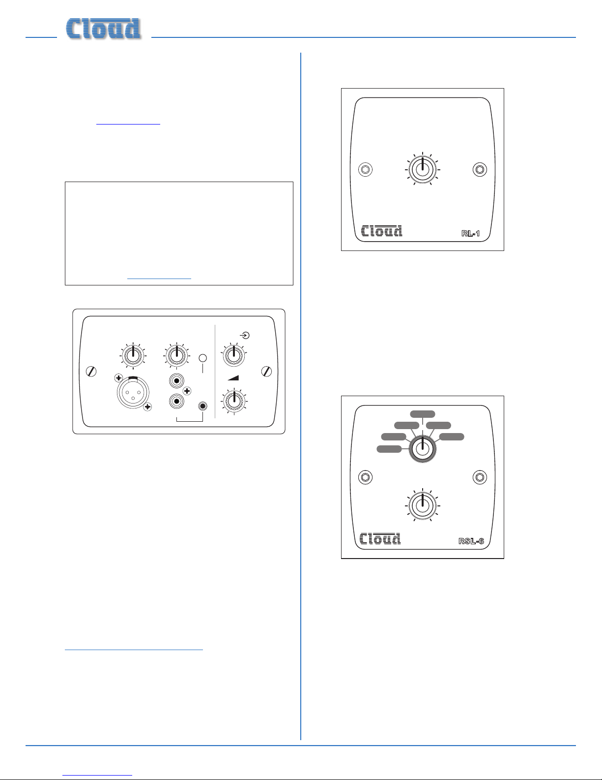
RL-1 Series Remote Music Level Controls
4
5
6
1
2
3
7
9
10
0
8
MUSIC LEVEL
RL-1
The RL-1 Series is a range of small plates with a single control
for locally adjusting the music level in a zone. They connect to
one of the 46-50’s REMOTE MUSIC CONTROL ports.
See page 15 and page 21 for more information.
RSL-6 Series Remote Music Level/
Source Controls
RSL 6-
1
2
345
6
MUSIC LEVEL
SOURCE SELECT
4
5
6
1
2
3
7
9
10
0
8
The RSL-6 Series is a range of plates allowing local (per-zone)
music source selection as well as music level control. They are
the same size as the RL-1s, and connect in a similar way. See
page 16 and page 21 for more information.
Page 9
46-50 Installation and User Guide V1.0
9
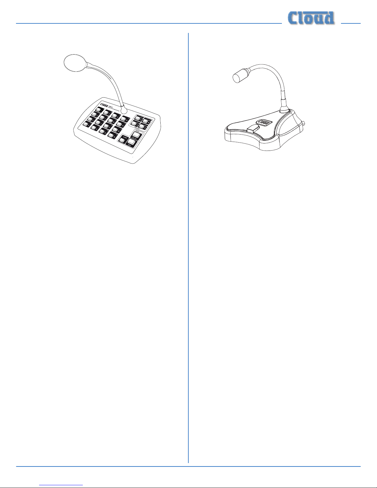
PM Series microphones
Cloud PM Series paging microphones may be connected
directly to the 46-50 using MIC 1 input and the PAGING
ACCESS port. Models are available which can page to 4, 8, 12
or 16 zones, and also to 4 or 8 zones with storage for built-in
spot announcements. As the 46-50 only supports four zones,
not all zones on the “higher” models can be accommodated
by a single 46-50; the PM4 and PM4-SA (4-zone) models are
most likely to be useful. See page 14 for more information.
The Cloud PM1 paging microphone is also compatible with
the 46-50. It is a much simpler unit which addresses a single
zone (although zones may be paralleled for wider access). See
page 15 for more information.
Page 10

46-50 Installation and User Guide V1.0
10
Block Diagram
MUSIC
EQ
MUSIC
VCA
SPEAKER
MODULE
LINE 6
LINE 5
LINE 4
LINE 3
LINE 2
LINE 1
LINE 6
PRIORITY
RELEASE
TIME
MUSIC
EQ
MUSIC
VCA
SPEAKER
MODULE
65Hz
65Hz
RSL-6 (OPTIONAL)
MIC 1
MIC 2
OFF
ON
OFF
ON
J7
J8
J23
PAGING MIC INTERF ACE
GA TE
PRIOR ITY
RSL-6 (OPTIONAL)
MIC 1
MIC 2
OFF
ON
OFF
ON
PAGING MIC INTERF ACE
GA TE
PRIOR ITY
ZONE 1
ZONE 2
ZONE 3
ZONE 4
FACILITY PORT
EQ
GAIN
MIC 1 INPUT
EQ
GAIN
MIC 2 INPUT
PHANTOM
POWER
PHANTOM
POWER
DYNAMIC CLIP
PROTECTION
DYNAMIC CLIP
PROTECTION
DYNAMIC CLIP
PROTECTION
DYNAMIC CLIP
PROTECTION
PROTECT
PROTECT
PROTECT
PROTECT
50W
POWER
AMP
50W
POWER
AMP
50W
POWER
AMP
50W
POWER
AMP
ZONE 2=J9
ZONE 3=J16
ZONE 4=J18
ZONE 2=J10
ZONE 3=J17
ZONE 4=J19
ZONE 2 = J22
ZONE 3 = J21
ZONE 4 = J20
SLA VE ZONE 3
AMP TO ZONE 4
ZONE 1
OUTPUT
Z1 AUX OUT
Z2 AUX OUT
ZONE 2
OUTPUT
ZONE 3
OUTPUT
ZONE 4
OUTPUT
OFF
ON
OFF
ON
J13
J15
ON
ON
J1
J25
J24
ON
OFF
J2
OFF
OFF 3s
6s
SLA VE
ZONE 2
AMP T O
ZONE 1
The simplied block diagram above illustrates the basic signal architecture of the 46-50.
Page 11

46-50 Installation and User Guide V1.0
11
Front panel description
0
1
SOURCESOURCESOURCESOURCE
MUSIC LEVELMUSIC LEVELMUSIC LEVELMUSIC LEVEL
MIC 2
MIC 1
LEVEL
1
2
3
4
5
6
HFLF
0
1010
10
0
-
dB
ZONE 1 MUSIC EQ
CLIP
MIC 2
MIC 1
LEVEL
1
2
3
4
5
6
HFLF
0
1010
10
0
-
dB
ZONE 2 MUSIC EQ
CLIP
MIC 2
MIC 1
LEVEL
1
2
3
4
5
6
HFLF
0
1010
10
0
-
dB
ZONE 2 MUSIC EQ
CLIP
MIC 2
MIC 1
LEVEL
1
2
3
4
5
6
HFLF
0
1010
10
0
-
dB
ZONE 2 MUSIC EQ
CLIP
ZONE 1ZONE 2 ZONE 3ZONE 4
4 ZONE 50W INTEGRATED
MIXER AMPLIFIER
3
569
4
1
9 8
27
Only Zone 1 controls indicated;
those for the other Zones are identical.
1. SOURCE – 6-way rotary switch selecting which Line Input (LINE 1 to LINE 6) will be the music source for each zone.
See page 18.
2. MUSIC LEVEL – adjusts the music level in each zone. See page 18.
3. MIC 1 – adjusts the level of the microphone connected to the rear panel MIC 1 input in each zone. See page 18.
4. MIC 2 – as [3], but controls level of MIC 2 input.
5. MUSIC EQ – two preset controls for adjusting HF/LF EQ in each zone. See page 18.
6. CLIP – per-zone red LEDs; illuminate when the output stage’s Dynamic Clip Limiter is active. This indicates that the level
is too high.
7. Power – rocker switch.
8. Zone idents – a space is provided above each zone’s controls for printed labels identifying the zone by name.
9. Fixing holes for security cover – prevents access to Zone EQ controls.
Page 12

46-50 Installation and User Guide V1.0
12
Rear panel description
2 22 11 15 13162
1
3 5 6 6 10 8 14 7 1254 9 9
1. LINE 1 to LINE 6 – six pairs of RCA (phono) sockets for connection of music sources. Inputs are stereo, summed
internally to mono. See page 13.
2. GAIN – preset trim control for each line input, providing ±10 dB of gain adjustment for input level matching. See page 18.
3. MIC 1 – balanced microphone input on 3-pin 3.5 mm-pitch screw-terminal connector. See page 14. This input
should be used in conjunction with the ACCESS CONTACTS connector [7] for paging.
4. MIC 2 – balanced input for a second microphone; 3-pin 3.5 mm-pitch screw-terminal connector.
5. GAIN – preset mic gain controls for MIC 1 and MIC 2, gain range 10 to 60 dB. See page 18.
6. MIC EQ – HF & LF preset EQ controls. See page 18.
7. PAGING ACCESS – 6-pin 5 mm-pitch screw-terminal connector for per-zone paging access by contact closure.
See page 14.
8. REMOTE MUSIC CONTROL – 3-pin 5 mm-pitch screw terminal connector for each primary zone, for connection of
RL-1/RSL-6 remote control plates. See page 15.
9. LOCAL/REMOTE – switches determine whether front panel music source and level controls will remain active when
remote control plates are connected (per-zone). See page 15.
10. ZONE 1 FACILITY PORT – 9-pin Dsub socket, for connection of remote input/control modules, or as an auxiliary
input. See page 16.
11. AUX OUT – unbalanced line level outputs for Zone 1 and Zone 2 at 0 dBu. See page 17.
12. SPEAKER OUTPUTS – low-impedance outputs for each of the four zones on 3-pin 3.5 mm-pitch screw-terminal
connector. See page 16.
13. 100V/70V OUTPUTS – location of output terminals for 70/100 V-line operation when CXL-4160 transformer module
is tted internally (either on Model 46-50T, or as retrotted option). See page 17.
14. MUSIC MUTE – 2-pin 5 mm-pitch screw terminal connector for connection of external emergency muting relay
(e.g., re control panel). See page 17.
15. Mains – IEC receptacle for AC mains. See page 13.
16. FUSE – mains fuse. See page 13 for fuse details.
Page 13

46-50 Installation and User Guide V1.0
13
INSTALLATION
Hardware considerations
The 46-50 Mixer Amplier is built in a 2U-high 19” rack mount
enclosure. It is recommended that the 46-50 is installed in a
19” rack wherever possible. The units are approx. 320 mm
deep, but at least 400 mm of rack depth should be available to
allow for rear connectors and cabling.
The 46-50 uses thermostatically-controlled forced-air cooling,
using a two-speed fan. The enclosure has air intake slots in
the front panel; ensure that these are not obstructed once
the unit is installed. Warmed air is expelled at the rear of
the unit by the fan. It is recommended that 1U blank panels
are tted in the rack above and below the 46-50; do not
t slotted ventilation panels as these defeat the action of
forced-air cooling.
If the unit is to be used free-standing (i.e., not mounted in a
rack), the four feet supplied in the accessory pack should be
tted to the bottom of the chassis. These should be inserted
into the four 5 mm dia. holes clearly identiable in the corners
of the bottom panel.
The choice of location will be dictated by the specics of the
system and building layout. It is recommended that wherever
possible, the 46-50 should be mounted adjacent to as many
of the music sources (CD players, music servers, TV receiver
boxes, etc.) as practical.
When deciding the Mixer Amplier’s location, bear in mind
that access to it (particularly the rear panel) will probably be
required even if a full complement of remote controls is being
tted as part of the system, as certain adjustments can only
be made on the unit itself.
Power Supply
The European version of the 46-50 operates on standard
230 V AC mains; an alternative version is available which
operates on 115 V AC. An IEC mains cable with a plug
appropriate for each country is supplied with the European
unit. The unit’s power consumption is 181 VA (measured using
8th-power pink noise driving 4 x 4 ohm loads).
Fuses and ratings
The only externally-accessible fuse is an AC mains fuse in the
IEC connector housing. Only replace a fuse with one of
exactly the same type. The table below gives the correct
fuse types.
VERSION RATING FUSE TYPE
230 V 3.15 A 20 mm x 5 mm slo-blo T3.15AH
115 V 6.3 A 20 mm x 5 mm slo-blo T6.3AH
The fuseholder is of the “bayonet” type; press and twist the
holder anticlockwise to remove the fuse. If a replacement
fuse blows immediately, it indicates that the mixer amplier
has developed a fault, which should be referred to competent
service personnel.
Internally, two 20mm x 5mm fast-blow F4.0A fuses protect
each amplier channel (eight in total). These are service
components, and should not require attention. Failure of any
of these fuses indicates a fault condition, which should be
immediately referred to a competent technician or authorised
service centre.
System connections
Music sources
Connect the system’s various music sources to LINE 1 to
LINE 6. All line inputs offer unbalanced connection for stereo
sources on a pair of standard RCA jacks (phono sockets).
The sensitivity range available should allow most standard
items of audio equipment such as computers/tablets, music
servers and media receivers, etc., to operate at a satisfactory
level. Most equipment of this type will have stereo unbalanced
outputs, and as long as the source equipment is adjacent to
the Mixer Amplier, normal phono-phono (or 3.5 mm jack-tophono) leads can be used. Always avoid using pre-made leads
of an unnecessary length.
Mono and stereo sources:
The mixing section of the 46-50 is mono; the stereo line inputs
are summed internally. Stereo sources should be connected
in a normal stereo conguration, using both L and R inputs.
If connecting a mono source with only a single output, it may
be connected to either the left or the right input.
Balanced sources:
If it is necessary to connect an item of source equipment with
a balanced output to the 46-50’s line inputs, ideally, a balancing
transformer should be inserted between the source and the
unbalanced input. Suitable audio transformers, which should
have a ratio of 1:1, are readily available from major audio
component suppliers. The transformer(s) should be mounted
as close to the 46-50 as practical, and housed in a screened
enclosure if they are not individually screened. The preferred
connection method is shown below.
LEFT
+
-
SCN
Unbalanced
inputs
SCN
LEFT
+
-
SCN
Audio balancingtransformers
RIGHT
+
-
SCN
Unbalanced
inputs
SCN
RIGH
T
+
-
SCN
pi
n1ground
pi
n2hot
pi
n3cold
Balanced
outputs (XLRs):
12
3
12
3
If transformers are not available, a balanced source may feed
an unbalanced input directly as long as care is taken over how
the connections are made. A variety of design techniques are
in use to implement balanced outputs in audio equipment,
Page 14

46-50 Installation and User Guide V1.0
14
and some designs require different wiring protocols to others,
but to connect only the ‘hot’ and ‘screen’ to the unbalanced
input while leaving the ‘cold’ unconnected has been found to
work satisfactorily in many situations. However, in all cases,
installers are advised to check the manuals with each item
for guidance on how the outputs should be connected to an
unbalanced input.
Microphone input
Inputs MIC 1 and MIC 2 are intended for the direct
connection of microphones. They are electronically balanced
and transformerless with an input impedance of greater than
2 kohms and optimised for use with microphones of 200 to
600 ohms impedance. The screw terminal input connectors
should be wired thus:
PIN CONNECTION
1 Screen
2 Signal ‘-‘ (cold)
3 Signal ‘+’ (hot)
Unbalanced microphones may be used by connecting pin 2
to pin 1 (cable screen) in the mating (male) screw-terminal
connector. 15 V phantom power is available, see page 18.
Either mic input may be routed to any of the zones in use,
at any level in each zone. Microphone priority may be set
so that any microphone announcements automatically reduce
the music level in that zone while the announcement is in
progress (see page 19 for more details.)
Paging system connections
Cloud PM Series paging microphones may be connected
directly to the 46-50.
Two connections are required: the paging mic audio signal
should be connected to the MIC 1 input ([3] on page 12)
and the control cable to the 6-pin PAGING ACCESS port
([7] on page 12). The pinout of the PAGING ACCESS
port is given below:
PIN NO. FUNCTION
1 0 V
2 Zone 1
3 Zone 2
4 Zone 3
5 Zone 4
6 +15 V
Connecting PM4/4SA paging microphones
These microphones are equipped with both digital and
analogue paging interfaces; with the 46-50, the analogue
interface is used. PM microphones are available in 4, 8, 12
or 16-zone versions; the installer should be sure he/she
understands how paging zones correspond to mixer zones
before commencing wiring. Although the 46-50 only supports
a maximum of four zones, there is no technical reason to
prevent a PM microphone being used in a restricted manner.
Standard two-core screened audio cable may be used for
the audio signal, and stranded multicore (6-core is suitable)
cable with an overall screen for the control cable. Note that
PM Series microphones may obtain their DC power from the
46-50, but SA versions and need an external PSU.
Connections on the PM microphone are made via the rear
cable access glands and screw terminal blocks on the main
internal PCB (TERM2 and TERM 8 in the case of a PM4).
Full connection details can be found in the PM Series
Installation and User Guide.
The diagram below shows the cable connections between a
PM4 and a 46-50, where power is supplied by the 46-50.
TERM8
TERM2
HOT COLDGNDZ1 Z2 Z3
Z4
MIC 1/TEL INPUT
Z1 Z2 Z30 V
PM4 PAGING MICROPHONE
46-50
Z5 Z6 Z7
Z8
TERM1
0V
+V
+VZ4
1 3
2
ACCESS CONTACTS
Note that the default factory setting routes MIC 1 to all
four zones at all times. In order for MIC 1 to function
correctly with a paging mic, internal jumpers J23 (Zone 1),
J22 (Zone 2), J21 (Zone 3) and J20 (Zone 4) should be
removed to enable the PAGING ACCESS connector.
See page 24 for jumper locations.
For automatic music ducking during an announcement,
internal jumper J12 must be in its ‘ON’ position.
See page 19 for further information.
Page 15

46-50 Installation and User Guide V1.0
15
Connecting a PM1 paging mic
The PM 1 is a simple, passive paging microphone suitable for
situations where announcements are always made to the
same zone(s). It can be connected directly to the 46-50 Mixer
Amplier, the control cable being wired to the pin(s) of the
PAGING ACCESS port corresponding to the zone(s) in
which announcements are required. Any or all of the zones
may be paralleled if multiple zones need to operate from the
PM1.
Either a single 2-pair individually-screened cable may be
used (this gives the neatest nish), or two separate standard
microphone cables. Connections on the PM1 are made via the
rear cable gland in the base and the screw terminal blocks on
the internal PCB (U2 and U3). Full connection details can be
found in the PM1 Installation and User Guide. Note that the
PM1 does not require DC power.
The diagram below shows the connections between a PM1
and a 46-50. Use of 2-pair cable is assumed; the same wiring
principle is adopted if separate cables are being used for audio
and control.
PAGING MIC INPUT
SCN COLD HOT N/O N/C GND
U2 AUDIO U3 ACCESS
ZONE ACCESS CONNECTOR
CONNECT TO
ZONE(S) IN USE
1 2 3
0V Z1 Z2 Z3 Z4 +V
46-50
PM1
Note that the default factory setting routes MIC 1 to all
four zones at all times. In order for MIC 1 to function
correctly with a paging mic, internal jumpers J23 (Zone 1),
J22 (Zone 2), J21 (Zone 3) and J20 (Zone 4) should be
removed to enable the PAGING ACCESS connector.
See page 24 for jumper locations.
For automatic music ducking during an announcement,
internal jumper J12 must be in its ‘ON’ position.
See page 19 for further information.
Connecting OEM paging microphones
Other manufacturers’ paging microphones may be used
with the 46-50, provided they make the microphone signal
available at a suitable level (the 46-50’s mic gain adjustment
range should be sufcient to accommodate most types), and
that paging zone selection is by simple “contact closure-toground”. Providing these conditions are met, the connection
method described above for a Cloud PM4, or for the PM1 in
the case of a single-zone mic, may be used.
Music control
Like many other Cloud products, the 46-50 allows remote
control of music level and source selection in each of the
primary zones. Cloud remote control plates from the RL-1
Series (music level only) and RSL-6 Series (music level and
source selection) provide an elegant solution, though control
via a DC voltage from third-party systems is also possible
(see page 21).
Both types of plate connect via the REMOTE MUSIC
CONTROL connectors for the relevant zone (see [8] on
page 12). These connectors are 3-pin 5 mm-pitch screw
terminal type; please refer to page 21 for additional
information regarding cable lengths, etc.
Connecting an RL-1 Series remote control plate
Wire the remote control plate as shown below. Either
single-core screened or twin-and-screen cable may be used;
in the case of the latter, ignore one of the cores. Maximum
reliable cable run is 100 m
123
REMOTE
SOURCE + LEVEL
123
REMOTE LEVEL CONTROL WIRING
RL-1
SINGLE-CORE SCREENED CABLE MAY BE USED
Before the RL-1 will operate, the zone’s Music Control Port
must be enabled by setting the adjacent push-button switch
([9] on page 12) to REMOTE (i.e., pressing it in). In this
setting, the zone’s front panel MUSIC LEVEL and SOURCE
controls become inoperative. As music source selection will
still be required from the mixer amplier’s front panel when
an RL-1 is in use, the REMOTE setting may be overridden for
the source selection control only by moving internal jumper
J3 (Zone 1), J4 (Zone 2), J5 (Zone 3) or J6 (Zone 4) on the
main internal PCB. See page 24 for location of internal
jumpers.
Page 16

46-50 Installation and User Guide V1.0
16
Connecting an RSL-6 Series remote control plate
Wire the remote control plate as shown below. Twin-andscreen cable should be used. Maximum reliable cable run is
100 m.
123
REMOTE SOURCE & LEVEL CONTROL WIRING
RSL-6
USE TWO-CORE SCREENED CABLE
123
REMOTE
SOURCE + LEVEL
Before the RSL-6 will operate, the zone’s Music Control
Port must be enabled by setting the adjacent push-button
switch ([9] on page 12) to REMOTE (i.e., pressing it in).
In this setting, the zone’s front panel MUSIC LEVEL and
SOURCE controls become inoperative.
Zone 1 Facility Port
Zone 1 of the mixer amplier is provided with a FACILITY
PORT in the form of a female 9-pin Dsub connector on the
rear panel. This may be used to connect a remote active input/
control module, but may also be used as a general-purpose
auxiliary balanced input (see page 22 for more information
on this application). Note that an audio source connected via
the FACILITY PORT will only be available in Zone 1, and
no other.
Active modules operate from DC power supplied by the
46-50. The current consumed by each module is minimal and
in the vast majority of installations there will be no power
supply issues.
The pinout of the FACILITY PORT connector is given in
the table below:
PIN USE
1 Remote source select
2 Remote level control
3 Balanced audio input hot (+)
4 Balanced audio input cold (-)
5 Noise Gate control
6 -15 V DC
7 +15 V DC
8 0 V DC
9 VCA control voltage
Connecting an LM-2 remote active module
The Cloud LM-2 remote active module may be connected
to the FACILITY PORT using screened Cat 5 cable.
(Note that as the cable carries analogue audio, only screened
Cat 5 should be used.) As the LM-2 is primarily designed for
use with RJ45 connectors (and is itself tted with an RJ45),
it is necessary to wire the screened Cat 5 cable to a mating
male 9-pin Dsub connector in order to use it with the 46-50.
This procedure, and details of how to congure the 46-50
to suit, are explained in full in Cloud Technical Note TN-007,
which may be downloaded as a PDF le from the Resources
page at www.cloud.co.uk.
Speaker outputs (Lo-Z)
The speaker output connector is an 8-pin, 5 mm-pitch
screw-terminal connector. Four mating 2-pin connectors are
supplied. The power amplier outputs for all four zones are
present on this connector. Connect to speakers using pairs of
terminals as shown in the table:
Panel marking Connect to:
1 0V Zone 1 output ‘-‘
2 Z1 Zone 1 output ‘+‘
3 0V Zone 2 output ‘-‘
4 Z2 Zone 2 output ‘+‘
5 0V Zone 3 output ‘-‘
6 Z3 Zone 3 output ‘+‘
7 0V Zone 4 output ‘-‘
8 Z4 Zone 4 output ‘+‘
Each output stage is designed to drive into an impedance
of not less than 4 ohms. Check the impedance of the
loudspeaker(s) in use and, taking into account any series
and/or parallel wiring, ensure that the total load on each
channel is not less than 4 ohms.
Page 17

46-50 Installation and User Guide V1.0
17
Speaker outputs (100/70 V-line
operation)
The 46-50 may be converted for 100/70 V-line operation by
the use of the Cloud CXL-4160 transformer module. This
module is tted internally, and consists of four independent
transformers with separate ying leads, so any or all outputs
of the 46-50 may be converted to 100 V and/or 70 V-line
operation as required.
The low-impedance outputs are still active, but
should not have a load connected to them while
the 70 V/100 V-line outputs are in use.
In the 46-50T model variant, the CXL-4160 is pre-installed
at the factory, and wired for 70 V-line operation. This can
be changed to 100 V-line operation (per-output) if wished
by moving on-board links. Alternatively, the standard
46-50 model may be modied for 100/70 V-line operation by
retrotting the CXL-4160 module, which is available from
Cloud Electronics as an option. Full installation instructions
are supplied with the module.
When the CXL-4160 is tted, an 8-pin parallel entry screwterminal connector occupies the blank connector slot [13] at
page 12. The connector is wired as shown below:
Panel marking Connect to:
1 Z1- Zone 1 output ‘-‘
2 Z1+ Zone 1 output ‘+‘
3 Z2- Zone 2 output ‘-‘
4 Z2+ Zone 2 output ‘+‘
5 Z3- Zone 3 output ‘-‘
6 Z3+ Zone 3 output ‘+‘
7 Z4- Zone 4 output ‘-‘
8 Z4+ Zone 4 output ‘+‘
If preferred, individual external transformers may be employed
to convert outputs for 100/70 V-line operation. A suitable
transformer is the CXL-40T, available as an accessory from
Cloud Electronics. A 19” rack tray for mounting multiples of
these is also available.
When using the 46-50 for 100/70 V-line operation, the 65 Hz
high-pass lters in each zone to be used in this mode should
be enabled. See page 18 for full details.
Auxiliary line outputs
In large zones, it may be necessary to use additional ampliers
to obtain the necessary power to drive a greater number of
loudspeakers, or to drive some loudspeaker types requiring
high power levels than the 50 W available from the 46-50’s
channels. To permit the connection of further ampliers (or
any other equipment), unbalanced outputs from the 46-50’s
pre-amplier sections for Zones 1 and 2 are available at the
rear panel phono (RCA) connectors labelled AUX OUT
Z1 & Z2.
All Zone1 and 2 controls and settings on the front and rear
panels (levels, source selection, priority settings, etc.) affect
the Auxiliary line outputs. However, note that their source is
pre the switchable 65 Hz high pass lters, thus any additional
ampliers connected at the AUX OUT outputs would need
to have hi-pass lters applied if they were being used to drive
100/70 V-line circuits.
Music Mute
External muting of music is available at the MUSIC MUTE
connector. National or Local Authority regulations governing
such systems may require that normal programme material
(i.e., music) should be muted in an emergency, to ensure that
any emergency messages are clearly audible.
The Music Mute input is on a 2-pin 5 mm-pitch screw-terminal
connector. It should be connected to the appropriate alarm
output on whichever building management system registers
the alarm (typically the Fire System). The alarm output must
be volt-free; if no such output is available, an intermediate
relay or other isolation device must be installed between the
alarm output and the Music Mute input.
REMOTE MUSIC MUTE TERMINATIONS
1 2
MUSIC MUTE
INPUT
RELAY
NORMALLY OPEN (NO)
CONNECTION
1 2
MUSIC MUTE
INPUT
RELAY
NORMALLY CLOSED (NC)
CONNECTION
Page 18

46-50 Installation and User Guide V1.0
18
SETTING UP & OPERATION
Music Inputs
Gain & level
To avoid dramatic changes in volume when switching between
sources, the 46-50’s music inputs are provided with preset
gain trim controls ([2] on page 12). These vary the input
sensitivity from -12 dBu (195 mV) to +8 dBu (2.0 V). When
setting the system up, play audio from all the sources in use
and listen to them one at a time in a convenient zone (ideally
that in which the mixer is located) at a reasonable volume.
Taking a source of “average” volume as the reference, the gain
controls of the others should be adjusted so that there is no
appreciable difference in volume between any of the sources.
(With a typical music source, setting the gain on its channel
to mid-way is a good starting point.) Note that consideration
may need to be given to the type of programme in use,
particularly if one or more sources are TV sound.
In normal operation, the music level in each primary zone
is set with the MUSIC LEVEL control on the front panel
([2] on page 11). This control will not be operative if the
corresponding rear panel LOCAL/REMOTE push-button is
set to REMOTE.
Note that the setting of the music level has no effect on
microphone volume.
Local/remote control
If a zone has an RL-1 or RSL-6 Series remote control plate
connected in any zone(s), the corresponding rear panel
LOCAL/REMOTE push-button(s) must be set to REMOTE
(button in) for the remote controls to be operative and for
the corresponding front panel controls to be disabled. Zones
without such plates should be set to LOCAL (button out).
The setting of the internal jumpers J3 to J6 (on the main PCB)
is also relevant. The default setting is SW. This means that the
method of zone music source selection will be determined by
the rear panel switch setting; the front panel control will make
the selection if LOCAL/REMOTE is set to LOCAL and via
a remote plate or other external control if set to REMOTE.
If a jumper is set to FR, the source selection will always be
made with the front panel control whatever is connected at
the rear panel or the setting of the LOCAL/REMOTE switch.
If external control of music level only (i.e., not source
selection) is required, J3 (Zone 1), J4 (Zone 2), J5 (Zone
3) and/or J6 (Zone 4) should be set to FR and the
LOCAL/REMOTE switch to REMOTE.
See page 24 for location of internal jumpers.
Microphone input
Phantom power
Both microphone inputs have 15 V phantom power available.
This will be adequate to power a wide range of condenser
microphones. (Some “studio quality” mics may require
a higher phantom voltage and thus necessitate an external
PSU.) To enable phantom power at a mic input, internal
motherboard jumpers J1 (MIC 1) and/or J2 (MIC 2) should
be moved to their ON position. See page 24 for jumper
location.
Phantom power should NOT be enabled if dynamic
microphones are to be used.
Gain & level
Both microphone inputs are provided with a rear panel
preset GAIN control ([5] on page 12). A wide range of
gain is available and there should be no problem in obtaining a
satisfactory level from any normal microphone.
The GAIN controls should be adjusted by speaking
normally into a microphone of the correct type. Turn the
front panel MIC LEVEL control up to maximum and listen
in a convenient zone; the rear panel gain control should be
carefully advanced until the mic volume is as loud as it is ever
likely to be needed, and then reduced slightly. There should be
no audible distortion. The use to which the microphone is to
be put should be borne in mind – karaoke is more likely to
overload the mic preamplier than spoken announcements, if
the gain is not set correctly.
In normal operation, the mic level in each primary zone is set
with the MIC LEVEL controls on the front panel ([3] on
page 11).
EQ
The mic input has associated HF and LF EQ controls ([6] on
page 12) These provide 10 dB of cut or boost at 5 kHz
and 100 Hz respectively and should be adjusted by listening
to achieve a clear mic sound. Again, the application should be
borne in mind when making adjustments.
High-pass lter
The mic input has a xed 100 Hz high-pass lter to remove
the lowest frequencies. This helps to reduce the effects of
breath blasts and microphone handling noise. The lter is
always in circuit.
Page 19

46-50 Installation and User Guide V1.0
19
Zone outputs
In normal operation, the music level in each zone will be
set by the front panel MUSIC LEVEL control, or by a
corresponding control on a remote plate.
EQ
The various zones in a building often have different acoustic
properties, and may also have different models of loudspeaker
installed. The 46-50 is tted with per-zone HF and LF EQ
adjustments for the music signal ([5] on page 11) to enable
the audio frequency response to be best matched to each
zone’s acoustics. The controls should be adjusted by listening;
up to 10 dB of cut or boost at 10 kHz (HF) and 50 Hz (LF) is
available. Note that these EQ adjustments do not affect the
frequency response of the microphone signal.
After the EQ has been adjusted during system commissioning,
the EQ presets may be made inaccessible by tting the
security cover (one supplied with each Mixer Amplier). See
page 23 for tting instructions.
High-pass lters
When the 46-50 is used to drive 70/100 V-line loudspeaker
systems, either via an internal CXL-4160 module (as in the
46-50T) or via external CXL-40T transformers, there is a risk
of transformer saturation at high levels and low frequencies.
To prevent this, each of the 46-50’s four channels is provided
with a switchable 65 Hz high-pass lter. This should be enabled
for any channel being used to drive 70/100 V-line systems.
The lters are enabled by moving internal main PCB jumpers
J7 (Zone 1), J9 (Zone 2), J16 (Zone 3) and J18 (Zone 4).
See page 24 for locations of PCB jumpers.
In the Model 46-50T, the jumpers are set with the lters
enabled at the factory for all channels.
Slave Mode
(using output stages in parallel)
In some installations, a higher power output may be required
in a zone than the 50 W the 46-50 power stages are rated
at. To meet this requirement, the 46-50’s output stages may
have their inputs recongured so that the ampliers driving
Zones 1 and 2 outputs are both driven by the signal in Zone
1. Similarly, the ampliers driving Zones 3 and 4 outputs may
both be driven by the signal in Zone 4. (Clearly, using this
option reduces the overall number of zone outputs available.)
The diagram below illustrates the options available:
Z2
Zone 2 pre-amp
Z1
Zone 1 pre-amp
Z3
Zone 3 pre-amp
Z4
Zone 4 pre-amp
POWER
AMPLIFIER
STAGES
J15
J13
Selection of parallel operation is made by moving internal
main PCB jumpers J15 (Zones 1 & 2) and/or J13 (Zones 3 &
4) from their default setting. See page 24 for locations of
PCB jumpers.
Priorities
The 46-50 offers several options for determining what
happens to music signals when announcements are made.
Mic-over-Music priority
Fully automatic, voice operated priority is available for
the two mic inputs. This is selected by internal main PCB
jumper J12, which is set ON at the factory to enable priority
operation. When enabled, all music signals will attenuate by
approximately 30 dB when the microphone is used; after the
announcement, the music signals will restore smoothly to
their former level.
If it is necessary to disable the priority function, to allow full
mic/music mixing, J12 should be set to its OFF position. See
page 24 for locations of PCB jumpers.
Mic 1-over-Mic 2 priority
It may sometimes be desirable to ensure that one microphone
always has priority over the other. The 46-50’s priority
control logic can be changed to ensure that Mic 1 always takes
precedence over Mic 2, by ensuring that the presence of a Mic
1 signal attenuates the Mic 2 signal.
To enable Mic 1-over-Mic 2 priority, the 470R resistor R220
should be taken out of circuit by cutting one leg. Note that
enabling this priority is not something that is easily reversed!
The location of R220 is included on the PCB jumper location
diagram at page 24.
Page 20

46-50 Installation and User Guide V1.0
20
Line 6 priority
It may sometimes be necessary for one music input to have
priority over all the others; for example, a jukebox in a bar,
or a digital sound store programmed to make automatic
announcements in a public space. Input LINE 6 may be set
to have priority in Zone 1 (only) over whichever source is
selected for the zone by its SOURCE control. This priority
is set by moving internal jumper J24. (The default setting is
‘OFF’.)
The “release” time may be set 3 s or 6 s by moving J25, or to
12 s by removing J25 altogether.
When the priority is selected, a signal present at Line 6 will
force Zone 1’s source selection to that input; when the signal
disappears, the previously-selected source will be restored
over the time constant selected by J25.
See page 24 for location of the internal jumpers.
Mic-over-Facility Port priority
If a remote active module is in use in Zone 1, it is possible to
give a microphone connected at the 46-50 itself (at MIC 1 or
MIC 2) priority over input sources connected at the module.
This might be desirable in function rooms, for example, where
building-wide announcements may need to interrupt any local
use.
This priority is set by internal main PCB jumper J14. The
default setting is ‘OFF’; in this position microphones or
other sources connected at remote input modules will be
autonomous and will not be overridden by announcements
made via the mixer’s mic inputs. Setting J14 to ‘ON’ will give
priority to Mic 1 or Mic 2. The release time following an
announcement is approx. 0.5 s.
Note that this priority is independent of the local MIC
PRIORITY function which can be selected on the remote
module.
Page 21

46-50 Installation and User Guide V1.0
21
OPTIONS AND ADDITIONAL INFORMATION
RL-1 and RSL-6 Series remote control plates – general considerations
Cloud RL-1 Series and RSL-6 Series remote control plates are available in three form factors, two t single-gang UK or American
electrical back boxes respectively; the third is a 50 x 50 mm “Media” module, suitable for “Euro-module” mounting frames
available in most European countries. Back boxes of either the recessed type or surface-mounting type may be used, providing
they are at least 25 mm deep.
The plates should be connected to the REMOTE MUSIC CONTROL port of the relevant zone using single- or twin-core
screened cable as described at page 15 and page 16. The plate terminations are conventional screw terminals and the
REMOTE MUSIC CONTROL port on the mixer is a 3-pin 5 mm-pitch screw terminal connector.
The remote control plates are passive and thus do not draw any current from the mixer.
Control of music source and level via external DC
It may be necessary in some installations to adjust the music level and select music source in one or more zones from an external
control system (e.g., Crestron, AMX, etc.). If the REMOTE MUSIC CONTROL ports are not required for RL-1/RSL-6 Series
remote control plates, they may be used to receive DC voltages from the external system to effect these adjustments.
Both music source selection and level can be controlled over their full ranges with a DC voltage of 0 to +10 V. The pinout of the
REMOTE MUSIC CONTROL port is as follows:
PIN USE
1 0 V ref.
2 Music level control (0 to +10 V)
3 Music source selection (0 to +10 V)
REMOTE
SOURCE+LEVEL
PORT
1
2
3
+15V
0V
MUSICVCA
MUSICSOURCE
SELECT
4k7
15k
CONTROL
SYSTEM
0VREF
LEVEL CONTROL
SOURCECONTROL
46-50
NOTE: If the control voltage source is not isolated from the power earth, there is a small risk of creating a ‘ground loop’ by
linking the mixer technical ground (0 V) to the ground (0 V) of the equipment supplying the control voltages. To minimise this
risk, we suggest that all pieces of equipment be in close proximity, and supplied from the same power outlet.
Music level
Music level in a zone may be varied over its full range by applying a DC voltage of between 0 V and +10 V to pin 2, the 0 V
reference being connected to Pin 1. 0 V on pin 2 corresponds to maximum level and +10 V will produce 60 dB of attenuation.
The rate of attenuation is approximately 165 mV/dB.
Note that there is an internal 4k7 “pull-up” resistor between pin 2 and the internal +15 V rail. If pin 2 is left “oating”, this
pull-up will result in full attenuation. The output impedance of the control voltage source should be low enough to overcome
the effect of this resistor.
Page 22

46-50 Installation and User Guide V1.0
22
Music source
Music source for a zone may be controlled by applying
various DC voltages of between 0 and +10 V to pin 3, the 0 V
reference being connected to pin 1. 0 V at pin 3 will select Line
input 6 and between +7.5 and +9 V will select Line input 1.
The other line inputs will be selected with intermediate
voltages. Taking pin 3 above +9 V will deselect all inputs,
making the zone effectively ‘off’ for music.
The table below lists the DC voltages required at pin 3 to
select each line input. The third column is the value of a
resistor which should be connected between pins 1 and 3 to
permanently ‘force’ a zone to a particular line input.
INPUT DC VOLTAGE RESISTOR VALUE
OFF >+9.0 V
Line 1 +7.5 V 16k
Line 2 +6.0 V 11k
Line 3 +4.5 V 6k8
Line 4 +3.0 V 3k9
Line 5 +1.5 V 1k8
Line 6 0 V short-circuit
Note that there is an internal 15k “pull-up” resistor between
pin 3 and the internal +15 V rail. If pin 3 is left “oating”, this
pull-up will cause ‘OFF’ to be selected. The output impedance
of the control voltage source should be low enough to
overcome the effect of this resistor.
Using the Facility Port as an auxiliary
zone input
The Facility Port provides a balanced audio input. If a port is
not connected to an active remote module, it may be used as
a direct input to Zone 1 from other equipment forming part
of the system (for example, a permanently installed DJ mixer
which only ever needs to route its output to Zone 1.)
Wire an external balanced source to the facility port as
shown below:
1
8
7
6
5
4
3
2
132
BALANCED
OUTPUT (e.g.XLR)
hot (+)
hot (+)
cold (-)
cold (-)
46-50 ZONE 1
FACILITY PORT (RJ45)
An unbalanced source may also be connected; the use of
balancing transformers is recommended
Fitting loudspeaker EQ cards
The 46-50 is compatible with various popular installed-sound
loudspeakers; a single-channel loudspeaker equalisation
module may be tted to any or all of the four outputs as
required, to optimise the frequency response of the channel
to the loudspeaker type being used.
The cards may be obtained from Cloud Electronics as
optional accessories. Please check the Cloud website
(www.cloud.co.uk) for makes and models of loudspeakers for
which compatible EQ cards are available.
To install equalisation modules, rst disconnect the
46-50 from the AC mains supply, then remove the top
cover (8 screws). The modules plug into the white 12-pin
in-line sockets labelled CON3 (Zone 1), CON4 (Zone 2),
CON7 (Zone 3) and CON8 (Zone 4) on the main PCB.
Refer to the main PCB layout diagram at page 24, and
proceed as follows:
1. For each of the channel(s) having the EQ cards tted,
remove the factory jumper adjacent to the 12-pin socket
as follows: J8 (Zone 1), J10 (Zone 2), J17 (Zone 3) and
J19 (Zone 4). We recommend leaving the jumper on one
pin to avoid losing it.
2. Plug the EQ card into the 12-pin socket, pressing gently
until it clicks into place. Note the mating connector on
the module has two small projections which engage with
two notches on one side of the socket, to aid orientation.
3. Replace the top panel using the same screws.
Fitting the CXL-4160 transformer
module
NOTE: Full installation instructions are included
with the transformer module.
The notes below are an abridged version.
The CXL-4160 transformer allows the 46-50 to be used with
100/70 V-line loudspeaker systems.
1. Disconnect the 46-50 from the mains and remove the
top cover.
2. Remove the blanking plate from the 100V/70V-LINE
OUTPUTS connector location on the rear panel;
retain the plate and screws, nuts and washers.
3. The CXL-4160 is preset for 70 V-line or 100 V-line
operation according to territory. If the alternative voltage
is required, change the solder links on the rear of the
CXL-4160 PCB.
4. Fit the module to the right-hand side of the 46-50
(viewed from the rear) by the eight hex spacers, using
the screws supplied. The rear connector should project
neatly through the vacated rear panel slot.
5. Plug the 8-pin connector on the ying lead assembly
(supplied) onto the 8-pin header on the CXL-4160 PCB.
Page 23

46-50 Installation and User Guide V1.0
23
6. Plug the 2-pin connectors on the other end of the ying
lead assembly onto the corresponding headers on the
46-50 main PCB (immediately behind the 100V/70V
LINE OUTPUTS). The wire pairs are colour-coded for
ease of identication. Note that any or all of the four
channels may be connected as required.
7. Enable the 65 Hz high-pass lters for the relevant channels
(J7, J9, J16 & J18). See page 24 for jumper locations.
8. Fit the two hex spacers supplied to the holes vacated in
Step 2 using the same screws, nuts and washers.
9. Replace the cover.
After connecting the 70/100 V-line loudspeaker system
(see page 17), t the blanking plate from Step 2 onto the
hex spacers (Step 8) over the connector, with the printed
warnings outwards.
Fitting the EQ security cover
A security cover is supplied with the 46-50 which can be tted
to the front panel to prevent access to the Zone EQ preset
controls. The MIC LEVEL, MUSIC LEVEL and SOURCE
controls remain accessible and the CLIP LED is still visible.
The panel is simply placed over the rotary control knobs
and secured in place with the four M3x6 hex-head screws
supplied.
Page 24

46-50 Installation and User Guide V1.0
24
APPENDIX
PCB jumper locations
The 46-50 has various internal jumpers, the setting of which may require alteration during installation. The diagram below shows
the locations of the internal jumpers (not to scale) on the internal PCBs, and the table below lists each jumper and its purpose,
together with the factory default setting.
Note that the 46-50 has various sub-boards in addition to the main PCB. One of these, the music control sub-board, carries
two jumpers (J24 and J25), but all other jumpers are on the main PCB. Note that some main PCB jumpers are located below
this sub-board, and to access these, it is necessary to remove the sub-board. This can be done by disconnecting the three ribbon
cables linking the sub-board to elsewhere in the unit (two remain captive to the sub-board), removing the eight SOURCE and
MUSIC LEVEL control knobs and shaft nuts, and then removing the three M3 screws at the rear of the sub-board.
Most jumpers have two possible positions; the black square in the symbol on the diagram below indicates the default setting.
If any jumpers need to be changed, turn the 46-50 off and disconnect it from the mains. Undo the eight screws securing the top
cover of the unit and remove it. Use a pair of small pliers to gently remove the jumpers from the PCB headers and reposition
them as required. Ret the top cover using the same screws.
The PCB diagram (which is as viewed from the rear of the unit) also shows the locations of the sockets for the optional
loudspeaker EQ cards (CON3, CON4, CON7 & CON8), resistor R220 (ref: Mic1-over-Mic 2 priority) and the Zone output
connectors (see page 22).
MUSIC CONTROL
SUB-BOARD
MAIN PCB
J3
LINE INPUT SUB-BOARD
J6J5J4
J24
J25
J1
J2
J20-J23
J15
J13
J14
J12
J18
J16
J7
J9
J19
J17
J8
J10
J11
CON 3
CON 4
CON 7
CON 8
Connectors for
CXL4160 transformer
assy.
Approx. location
of R220
Page 25

46-50 Installation and User Guide V1.0
25
Table of internal jumpers and default settings
The table below lists each jumper and its purpose, together with location and factory default setting.
JUMPER LOCATION DESCRIPTION EFFECT DEFAULT
J1 Main board Mic 1 phantom power
OFF: MIC 1 phantom power OFF
ON: MIC 1 phantom power ON
OFF
J2 Main board Mic 2 phantom power
OFF: MIC 2 phantom power OFF
ON: MIC 2 phantom power ON
OFF
J3 Main board Music source selection – Zone 1
SW: Source follows rear panel MUSIC CONTROL switch
FR: Always via front panel only (Z1)
SW
J4 Main board Music source selection – Zone 2
SW: Source follows rear panel MUSIC CONTROL switch
FR: Always via front panel only (Z2)
SW
J5 Main board Music source selection – Zone 3
SW: Source follows rear panel MUSIC CONTROL switch
FR: Always via front panel only (Z3)
SW
J6 Main board Music source selection – Zone 4
SW: Source follows rear panel MUSIC CONTROL switch
FR: Always via front panel only (Z4)
SW
J7 Main board Zone 1 65 Hz High Pass Filter
OFF: full frequency response
ON: 65 Hz hi-pass lter enabled for Zone 1
OFF
1
J8 Main board Zone 1 EQ module bypass
PRESENT: No EQ module tted in CON 3
ABSENT: EQ module tted in CON 3
PRESENT
J9 Main board Zone 2 65 Hz High Pass Filter
OFF: full frequency response
ON: 65 Hz hi-pass lter enabled for Zone 2
OFF
1
J10 Main board Zone 2 EQ module bypass
PRESENT: No EQ module tted in CON 10
ABSENT: EQ module tted in CON 10
PRESENT
J11 Main Board NO/NC Mute contacts
N/O: contact closure required for muting
N/C: contact opening required for muting
N/O
J12 Main board Mic over music priority
OFF: No priority – mics mix with music
ON: Music ducks when mics in use
ON
J13 Main board Zone 3 & 4 Slave mode
OFF: Zone 3 power stage input = Zone 3 signal
ON: Zone 3 power stage input = Zone 4 signal
OFF
J14 Main board Mic over Facility input priority
OFF: No priority
ON: MIC 1 & 2 have VOX-triggered priority over signals at
Facility Port
OFF
J15 Main board Zone 1 & 2 Slave mode
OFF: Zone 2 power stage input = Zone 2 signal
ON: Zone 2 power stage input = Zone 1 signal
OFF
J16 Main board Zone 3 65 Hz High Pass Filter
OFF: full frequency response
ON: 65 Hz hi-pass lter enabled for Zone 3
OFF
1
J17 Main board Zone 3 EQ module bypass
PRESENT: No EQ module tted in CON 7
ABSENT: EQ module tted in CON 7
PRESENT
J18 Main board Zone 4 65 Hz High Pass Filter
OFF: full frequency response
ON: 65 Hz hi-pass lter enabled for Zone 4
OFF
1
J19 Main board Zone 4 EQ module bypass
PRESENT: No EQ module tted in CON 8
ABSENT: EQ module tted in CON 8
PRESENT
J20 Main board Mic1, Zone 1 Access Bypass
PRESENT: Mic has permanent access to Z1
ABSENT: Use access port to enable access to Z1
ON
J21 Main board Mic1, Zone 2 Access Bypass
PRESENT: Mic has permanent access to Z2
ABSENT: Use access port to enable access to Z2
ON
J22 Main board Mic1, Zone 3 Access Bypass
PRESENT: Mic has permanent access to Z3
ABSENT: Use access port to enable access to Z3
ON
J23 Main board Mic1, Zone 4 Access Bypass
PRESENT: Mic has permanent access to Z4
ABSENT: Use access port to enable access to Z4
ON
J24
Music Control
sub-board
Zone 1 Line 6 priority
OFF: No priority
ON: Line 6 has VOX-triggered priority over other sources in
Zone 1
OFF
J25
Music Control
sub-board
Zone 1 Line 6 priority release time
3S: 3 seconds. release time
6S: 6 seconds release time
ABSENT: 12 seconds release time
6S
1. These jumpers are factory-set to ON in Model 46-50T.
Page 26

46-50 Installation and User Guide V1.0
26
EMC considerations
The Cloud 46-50 fully conforms to the relevant electromagnetic compatibility (EMC) standards and is technically well behaved;
you should experience no operational problems and under normal circumstances, no special precautions need to be taken.
If the unit is to be used within close proximity to potential sources of HF disturbance such as high power communications
transmitters, radar stations and the like, the performance of the mixer may be reduced; we suggest that the microphone cable
screen be connected to the shell of the XLR type connector and the line input leads are kept as short as possible.
Ground loops
If, despite your best efforts, the completed sound system ‘hums’ you probably have a ‘ground loop’. The offending signal source
can often be identied by setting the volume control to minimum, then disconnecting the input leads (both left & right channels)
on each line input until the ‘hum’ disappears. This problem is often caused by terminating a screened input cable into a signal
source positioned a signicant distance from the mixer. A good way of avoiding this potential problem is to use signal sources
(typically ‘consumer’ equipment) that are double insulated with no connection to the mains supply earth. If a signal feed were
derived from a second mixer (a club or microphone mixer for example) it would be perfectly normal to expect this to be
earthed; we suggest that a transformer be used to isolate the signal and prevent a noisy loop (see page 13).
TECHNICAL SPECIFICATIONS
Technical specications
Line Inputs
Frequency Response 20Hz – 20KHz +/-0.5dB
Distortion <0.03%, 20 Hz to 20 kHz
Sensitivity 195 mV (-12 dBu) to 2.0 V (+8 dBu)
Input gain control range 20 dB
Input Impedance 47 kohms
Headroom >20 dB
Noise -90 dB (0 dB gain, 22 Hz to 22 kHz)
Equalisation HF: ±10 dB @10 kHz; LF: ±10 dB @ 50 Hz
Microphone Inputs
Frequency Response 100 Hz -3 dB (xed lter) to 20 kHz ±0.5 dB
Distortion <0.05%, 20 Hz to 20 kHz
Gain Range 0 dB to 50 dB
Input Impedance >2 kohms (balanced)
Common mode rejection >70 dB @ 1 kHz
Headroom >20 dB
Noise -128 dB EIN, 22 Hz to 22 kHz (Rs = 150 ohms)
Equalisation HF: ±10 dB @ 5 kHz; LF: ±10 dB @ 100 Hz
Outputs
Low Impedance
Outputs
4 ohm load 50 W
8 ohm load 35 W
Auxiliary Outputs (Zones 1 & 2) 0 dBu (unbalanced)
100 V-line Output* 100 V balanced – 250 ohm min. load
70 V-line Output* 70 V balanced – 125 ohm min. load
Amplier protection
Dynamic Clip Protection, VI Limiting, DC Offset, thermal & switch-on
delay
Cooling Variable speed DC fan
* with optional CXL-4160 module tted internally
Page 27

46-50 Installation and User Guide V1.0
27
GENERAL SPECIFICATIONS
Power input 230 V ±5% (115 V ±5% available)
Fuse rating 230 V: T3.15AH; 115 V: T6.3AH
Fuse type 20 mm x 5 mm 250 V
Dimensions (wxhxd)
Net
482.6 mm x 88 mm (2U) x 382 mm deep
19” x 3.5” x 15”
Shipping (Gross)
610 mm x 200 mm x460 mm
24” x 8” x 18”
Weights
Net 7.65 kg /17 lbs (46-50); 10.5 kg / 23.1 lbs (46-50T)
Shipping (Gross) 10.2 kg / 23 lbs (46-50); 13.0 kg / 29.1 lbs (46-50T)
Page 28

Cloud Electronics Limited
140 Staniforth Road
Shefeld S9 3HF
England
Tel: +44 (0)114 244 7051
Fax: +44 (0)114 242 5462
email: info@cloud.co.uk
web: www.cloud.co.uk
Cloud Electronics USA
1200 Iron Horse Drive,
Unit A, Park City,
Utah 84060.
United States of America.
Toll Free: 0855 810 0161
Web: www.cloudusa.pro
E-mail: sales@cloudusa.pro
 Loading...