

Page 1
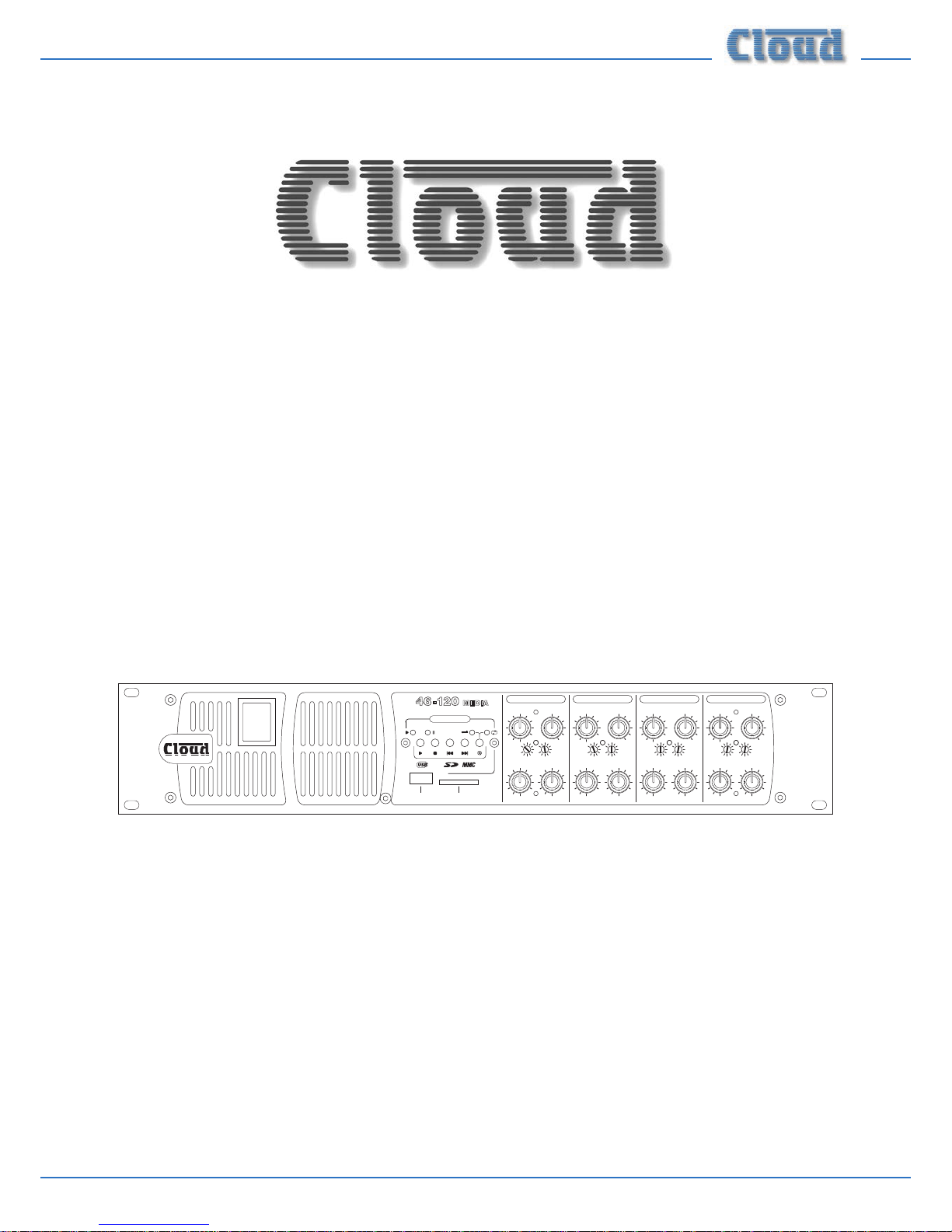
46-120 Installation and User Guide V1.1
MULTI-ZONE
MIXER AMPLIFIERS
46-120
46-120MEDIA
46-120T
46-120T
MEDIA
Installation and User Guide
0
1010
10
0
-
d B
000
101010 101010
101010
000
---
d Bd Bd B
H FH FH FH F LFLFLFLF
1
2
3
4
5
6
1
2
3
4
5
6
1
2
3
4
5
6
1
2
3
4
5
6
CLIPCLIPCLIPCLIP
LEV EL LEV EL LEV EL LEV EL
Z ONE 4 MUSIC EQZ ONE 3 MUSIC EQZ ONE 2 MUSIC EQ
Z ONE 1 MUSIC EQ
MIC 2 MIC 2 MIC 2 MIC 2
MIC 1 MIC 1 MIC 1 MIC 1
SOURCESOURCESOURCESOURCE
MUSIC LEV ELMUSIC LEV ELMUSIC LEV ELMUSIC LEV EL
Z ONE 1 Z ONE 2 Z ONE 3 Z ONE 4
PLAY
PAUSE
RANDOM
REPEAT
MEDIA PLAY ER
USB MEMORY CARD
12046 MEDIA-
4 Z ONE 120W INTEG RATED MIX ER AMPLIF IER
0
1
Page 2
46-120 Installation and User Guide V1.12
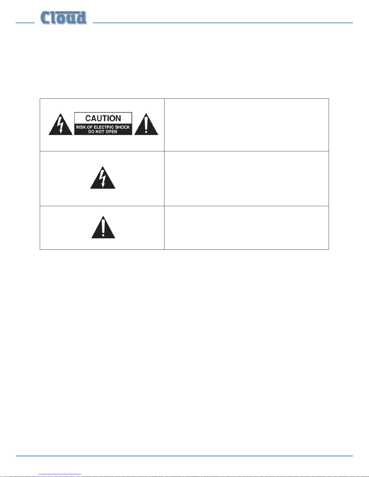
WARNING:
To reduce the risk of re or electric shock, do not expose this appliance to rain or moisture.
CAUTION:
Use of controls or adjustments or performance of procedures other than those specied may result in hazardous radiation
exposure.
WARNING: SHOCK HAZARD – DO NOT OPEN
AVIS: RISQUE DE CHOC ELECTRIQUE – NE PAS OUVRIR
The lightning ash with the arrowhead symbol within an equilateral
triangle, is intended to alert you to the presence of uninsulated
dangerous voltages within the product’s enclosure that may be of
sufcient magnitude to constitute a risk of electric shock.
The exclamation point within an equilateral triangle is intended to
alert the user to the presence of important operating and maintenance
(servicing) instructions in the literature accompanying the appliance.
Page 3

46-120 Installation and User Guide V1.1 3
IMPORTANT SAFETY INSTRUCTIONS
1. Read these Instructions.
2. Keep these Instructions.
3. Heed all Warnings.
4. Follow all Instructions.
5. Do not use this apparatus near water.
6. Clean only with a dry cloth.
7. Do not block any ventilation openings. Install in accordance with the manufacturers’ instructions.
8. Do not install near any heat sources such as radiators, heat registers, stoves or other apparatus (including ampliers) that
produce heat.
9. Do not defeat the safety purpose of the polarized or grounding - type plug. A polarized plug has two blades with one wider
than the other. A grounding type plug has two blades and a third grounding prong. The wide blade or the third prong are
provided for your safety. When the provided plug does not t into your outlet, consult an electrician for replacement of
the obsolete outlet.
10. Protect the power cord from being walked on or pinched particularly at plugs, convenience receptacles, and the point
where they exit from the apparatus.
11. Only use attachments/accessories specied by the manufacturer.
12. Use only with the cart, stand, tripod, bracket or table specied by the manufacturer or sold with the apparatus,
when a cart is used, use caution when moving the cart/apparatus combination to avoid injury from tip-over.
13. Unplug this apparatus during lightning storms or when unused for long periods of time.
14. Refer all servicing to qualied service personnel. Servicing is required when the apparatus has been damaged in any way,
such as power-supply cord or plug is damaged, liquid has been spilled or objects have fallen into the apparatus, the apparatus
has been exposed to rain or moisture, does not operate normally, or has been dropped.
Do not expose the apparatus to dripping or splashing, and ensure that no objects lled with water, such as vases, are
placed on the apparatus.
L’appareil ne doit être exposé aux écoulements ou aux éclaboussures et aucun objet ne contenant de liquide, tel
qu’un vase, ne doit être placé sur l’appareil.
The mains plug is used as the disconnect device and it should remain readily accessible during intended use. In order
to isolate the apparatus from the mains, the mains plug should be completely removed from the mains outlet socket.
Le prise du secteur ne doit pas être obstruée ou doit être facilement accessible pendant son utilisation. Pour être
complètement déconnnecté de l’alimentation d’entrée, la prise doit être débranchée du secteur.
This apparatus is of Class 1 construction and must only be connected to a mains outlet socket with a protective
earthing connection.
Terminals marked with the symbol may use Class 2 Wiring, but voltages at these terminals may be of sufcient
magnitude to constitute a risk of electric shock. The external wiring connected to these terminals requires
installation by an instructed person or the use of pre-made leads or cords.
Page 4

46-120 Installation and User Guide V1.14
Contents
SAFETY INFORMATION ............................................................................................................. 6
Safety Notes regarding Installation ............................................................................................................................ 6
Conformities ................................................................................................................................................................... 6
Safety Considerations and Information .................................................................................................................... 6
Caution – High Voltage .............................................................................................................................................. 6
Caution – Mains Fuse ................................................................................................................................................ 6
Caution – Servicing .................................................................................................................................................... 6
OVERVIEW ..................................................................................................................................... 7
Introduction .................................................................................................................................................................... 7
Scope of this manual ..................................................................................................................................................... 7
What’s in the box .......................................................................................................................................................... 7
Key features..................................................................................................................................................................... 8
Optional system components ..................................................................................................................................... 8
CDI-46 digital interface ............................................................................................................................................. 8
LM-2 remote active modules ................................................................................................................................... 8
RL-1 Series ................................................................................................................................................................... 9
RSL-6 Series ................................................................................................................................................................. 9
PM Series paging microphones ................................................................................................................................ 9
Block Diagram .............................................................................................................................................................. 10
Front panel description ...........................................................................................................................................11
Rear panel description ............................................................................................................................................ 12
INSTALLATION ........................................................................................................................... 14
Hardware considerations ...........................................................................................................................................14
Power Supply ................................................................................................................................................................ 14
Fuses and ratings ....................................................................................................................................................... 14
System connections ..................................................................................................................................................... 14
Music sources ............................................................................................................................................................14
Microphone input ..................................................................................................................................................... 15
Zone 1 Facility Port ................................................................................................................................................. 15
Paging system connections ..................................................................................................................................... 16
Music control ............................................................................................................................................................. 17
CDI-46 digital interface ...........................................................................................................................................18
Speaker outputs ........................................................................................................................................................ 19
Auxiliary line outputs ..............................................................................................................................................20
Music Mute ................................................................................................................................................................. 20
Remote Power Down ..............................................................................................................................................20
SETTING UP & OPERATION .................................................................................................... 21
Music Inputs .................................................................................................................................................................. 21
Gain & level ................................................................................................................................................................ 21
Local/remote control ............................................................................................................................................... 21
Page 5

46-120 Installation and User Guide V1.1 5
46-120MEDIA digital media player ..............................................................................................................................21
Compatible media .................................................................................................................................................... 21
File types and rates supported ..............................................................................................................................21
Basic operation ......................................................................................................................................................... 22
Microphone inputs ....................................................................................................................................................... 22
Phantom power ........................................................................................................................................................ 22
Gain & level ................................................................................................................................................................ 22
EQ ................................................................................................................................................................................ 22
High-pass lter .......................................................................................................................................................... 22
Use of Mic 1 with a telephone system ................................................................................................................ 22
Zone and MOH/Utility outputs ................................................................................................................................ 23
EQ ................................................................................................................................................................................ 23
MOH/Utility output settings .................................................................................................................................. 23
High-pass lters ........................................................................................................................................................ 23
Priorities ........................................................................................................................................................................ 24
Mic-over-Music priority ...........................................................................................................................................24
Line 6 priority ............................................................................................................................................................ 24
Mic-over-Facility Port priority ............................................................................................................................... 24
Control ........................................................................................................................................................................... 24
CDI-46 digital interface ...........................................................................................................................................24
Auto Power Down ...................................................................................................................................................25
OPTIONS AND ADDITIONAL INFORMATION..................................................................... 26
LM-2 remote active module – general considerations ........................................................................................ 26
Connecting multiple LM-2s ....................................................................................................................................26
In-zone sources ......................................................................................................................................................... 26
In-zone remote control ........................................................................................................................................... 26
Using the Facility Port as an auxiliary zone input .............................................................................................26
RL-1 and RSL-6 Series remote control plates – general considerations ........................................................ 26
Control of music source and level via external DC .........................................................................................26
Fitting the CDI-46 digital interface ..........................................................................................................................27
Fitting loudspeaker EQ cards .................................................................................................................................... 28
Fitting CXL-46T transformers ..................................................................................................................................28
Bypassing transformers in the 46-120T and 46-120T
MEDIA ..........................................................................................29
Fitting the EQ security cover .................................................................................................................................... 29
APPENDIX ................................................................................................................................... 30
PCB jumper locations ................................................................................................................................................. 30
Table of internal jumpers and default settings ................................................................................................... 31
PSU capability and optional device current consumption ..................................................................................32
EMC considerations .................................................................................................................................................... 32
Ground loops ............................................................................................................................................................ 32
Technical specications ............................................................................................................... 33
General specications .................................................................................................................. 34
Page 6
46-120 Installation and User Guide V1.16
SAFETY INFORMATION
Safety Notes regarding Installation
• Do not expose the unit to water or moisture.
• Do not expose the unit to naked ames.
• Do not block or restrict any air vent.
• Do not operate the unit in ambient temperatures above
35° C.
• Do not touch any part or terminal carrying the hazardous
live symbol
while power is supplied to the unit.
• Do not perform any internal adjustments unless you
are qualied to do so and fully understand the hazards
associated with mains-operated equipment.
• The unit has no user-serviceable parts. Refer servicing to
qualied service personnel.
• If the moulded plug is cut off the AC power lead for
any reason, the discarded plug is a potential hazard and
should be disposed of in a responsible manner.
Conformities
This product conforms to the following European EMC
Standards:
BS EN 55103-1:2009
BS EN 55103-2:2009
This product has been tested for use in commercial and
light industrial environments. If the unit is used in controlled
EMC environments, the urban outdoors, heavy industrial
environments or close to railways, transmitters, overhead
power lines, etc., the performance of the unit may be degraded.
The product conforms to the following European electrical
safety standard:
BS EN 60065:2012
Safety Considerations and
Information
All versions of the Cloud 46-120 must be earthed. Ensure
that the mains power supply provides an effective earth
connection using a three-wire termination.
Caution – High Voltage
Do not touch any part or terminal carrying the hazardous live
symbol while power is applied to the unit. Terminals to
which the hazardous live symbol refers require installation by
a qualied person.
Caution – Mains Fuse
The 46-120 contains no user-replaceable fuses. Mains
over-current protection is provided by the fuse in the IEC
receptacle; only replace this fuse with one of an identical type
and rating.
Caution – Servicing
The unit contains no user-serviceable parts. Refer servicing to
qualied personnel. Do not perform servicing unless you are
qualied to do so. Disconnect the power cable from the unit
before removing the top panel and do not make any internal
adjustments with the unit switched on. Only reassemble the
unit using bolts/screws identical to the original parts.
Page 7

46-120 Installation and User Guide V1.1 7
OVERVIEW
Introduction
Thank you for purchasing this Cloud Multi-Zone Mixer
Amplier. We are condent that you will be pleased with its
performance, features, exibility and reliability.
The Cloud 46-120 is an integrated, analogue audio mixer
amplier. It combines simple control of background music
for four independent zones with versatile microphone paging
and power amplication in a single unit. It is suitable for use
in many types of premises, including pubs, bars, clubs, shops,
ofces, hotels, etc. It is compatible with Cloud PM Series
paging microphones and is also designed to interface with
most third-party paging microphones conforming to industry
standards.
Scope of this manual
This manual provides a comprehensive guide to the features
and functionality of all models of the Cloud 46-120 Integrated
Mixer Amplier. The 46-120 is available in four versions, with
or without an integral digital music player and/or with preinstalled transformers for 70 V-line operation (recongurable
for 100 V-line operation), as follows:
• 46-120 four-zone Mixer Amplier
• 46-120T four-zone Mixer Amplier with 70 V-line outputs
(100 V congurable)
• 46-120
MEDIA four zone Mixer Amplier with integral
digital music player
• 46-120T
MEDIA four-zone Mixer Amplier with integral
digital music payer and 70 V-line outputs (100 V
congurable)
Apart from the additional functionality provided by the music
player in the MEDIA versions, all 46-120 models are identical
in facilities and features. Unless specically stated otherwise,
the reference “46-120” can be taken to apply to all four
models throughout this User Guide, and all instructions and
guidance in the Guide can be assumed to be relevant to all
models.
Please read through the manual to become fully acquainted
with the various conguration and control functions the
46-120 offers.
The manual is arranged as follows:
• Overview – introduction to the 46-120 and its options.
• Installation – wiring the 46-120 in a practical situation.
• Setting Up & Operation – setting the system up and
user instructions.
• Options and Additional Information – additional
information about system options.
• Appendix – additional technical information (includes
technical specications).
The 46-120 manual includes basic information on interfacing
Cloud PM Series paging microphones and connecting Cloud
LM-2 remote active modules and RL-1/RSL-6 Series remote
control plates. An overview of the additional facilities provided
by the optional CDI-46 digital interface card is also included.
Full installation information for each of these options is
supplied with the items themselves.
Thank you again for placing your condence in Cloud products.
What’s in the box
Unpack the 46-120 and its accessories with care. It is always a
good idea to store all packaging (if practical), in case you ever
need to return the unit to your Cloud dealer for any reason.
As well as this manual, the shipping carton should contain
the items listed below. Please contact your Cloud dealer
immediately if any of them are missing or damaged.
• Cloud 46-120 Multi-Zone Mixing Amplier
• IEC mains lead (AC cord) with moulded plug appropriate
to the territory
• Set of mating connectors for all rear panel multi-pin
screw-terminal connectors
• Set of four plastic feet, with xings
• Front panel security cover (prevents access to Zone EQ
controls)
• 4qty M3 x 6 hex-head screws for security cover
• 2 mm hex key (for security cover screws)
Page 8
46-120 Installation and User Guide V1.18
Key features
• Mixer amplier for four zones
• Built-in digital music player supports MP3 and WMA les
from USB memory sticks or SD cards at all standard data
rates/sample frequencies (MEDIA versions only)
• Six (unbalanced) stereo line inputs with individual gain
trim controls
• Front panel user controls for music source, music level
and level of each microphone, for each zone, plus preset
controls for HF/LF EQ
• Two balanced mic inputs; 15 V phantom power selectable
on either or both
• MIC 1 input can be congured as telephone system
interface
• Contact closure access port for paging zone selection –
most OEM paging systems supported
• Sensitivity and HF/LF EQ adjustment for mic inputs (rear
panel)
• Selectable VOX-triggered mic-over-music priority
• Selectable LINE 6 priority in Zone 1, with choice of
release times
• 4 x 120 W power output (4 ohms)
• Transformer-isolated auxiliary output with independent
mic and music level control - for use with telephone
MOH systems
• Aux output source selection (internal jumper) – xed
source or mix of Mic 1 and Zone 1 music source
• Zones 1 & 2 auxiliary line level outputs (pre-power
amplier), for connection of additional external ampliers
• Optional CXL-46T 70/100 V transformer can be tted
internally to any or all zone outputs (pre-tted to all
channels in T versions)
• Selectable 65 Hz high-pass lter per-output (for use with
70/100 V-line systems)
• Music Mute control input (N/O or N/C) for interface to
emergency system
• Zone 1 Facility Port (RJ45) for connection of optional
LM-2 mic/line remote input/control modules via Cat 5
• Compatible with standard Cloud remote control plates:
RL Series (music level) and RSL Series (music level and
source selection), per-zone
• Optional EQ cards available to suit various popular
installation loudspeakers may be tted in any or all
outputs
• Optional CDI-46 digital interface card with Cloud
Digital Paging System port for direct interface to PM
Series paging microphones, RS-232 serial port and RJ45
Ethernet port
• Energy-saving auto power-down function, Ethernetcontrollable (when CDI-46 is tted)
• Remote standby mode control by contact closure
• Variable–speed fan cooling
• 2U 19” rack-mounting unit
Optional system components
The following components may form part of the audio system
and may be ordered separately if required. They may also be
retrotted to a system at a later time. Separate datasheets
are available for each of the individual components; download
them at www.cloud.co.uk.
Note that full installation and operation instructions are
supplied with each optional component.
CDI-46 digital interface
The CDI-46 card is an optional accessory which gives the
46-120 additional interface and control capabilities. The
CDI-46 is equipped with both Ethernet and RS-232 ports,
allowing the mixing amplier’s primary functions to be
controlled from external systems (Crestron, AMX, etc.) using
either protocol. The card also acts as an Ethernet-to-serial
bridge, converting Ethernet commands to other equipment
into RS-232 data. See page 18 and page page 24 for more
details.
The CDI-46 is also tted with a Cloud Digital Paging interface
(the CDPM/PM INPUT). This provides the simplest method
of connecting Cloud PM Series Paging Microphones, requiring
only a single standard Cat 5 cable. See page 18 for more
details.
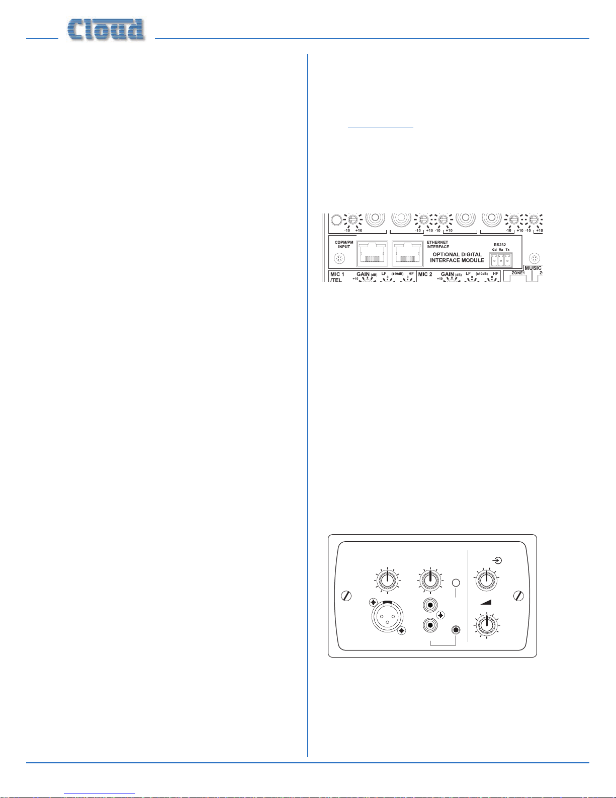
LM-2 remote active modules
MIC LEVEL
1
2
3
4
5
6
MUSIC LEVEL
LINE INPUT
MIC INPUT
LM-2
MIC
PRIORITY
1
4
5
2
3
6
7
9
10
8
0
1
4
5
2
3
6
7
9
10
8
0
1
4
5
2
3
6
7
9
10
8
0
The LM-2 is an active input module which allows a microphone
and a stereo line input in a remote location to be connected
to the 46-120. The faceplate has both phonos and a 3.5 mm
jack socket for connection of the line input, and provides a
convenient access point for the connection of a DJ mixer,
laptop, MP3 player or similar. Mic and line inputs have separate
level controls. A MIC PRIORITY button activates the Mixer
Page 9
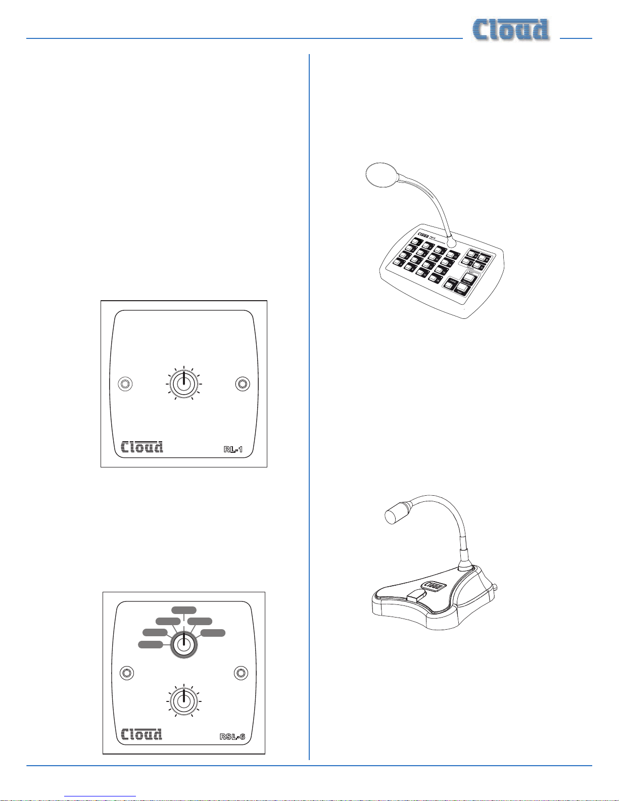
46-120 Installation and User Guide V1.1 9
Amplier’s priority circuitry; when enabled, a microphone
signal from the LM- 2 will reduce the music level in the zone
where it is installed. Changing a rear jumper alters the priority
operation so that the mixed mic and line signals from the
module cause the mixer’s line input selected to the Zone to
be fully muted.
The module also includes the functions of the RSL-6 Remote
Control Plate (see below), permitting control of zone music
level and source. See page 15 and page 26 for more
information.
The LM-2 connects to the 46-120’s ZONE 1 FACILITY
PORT via screened Cat 5 cable, and the remote sources are
routed to Zone 1. The mixer’s Mic inputs remain available.
Multiple LM-2s in Zone 1 may be daisy-chained to provide
mic inputs in more than one position in the zone. The LM-2
is available in sizes to suit UK, US and German electrical back
boxes; a choice of nishes is also available.
RL-1 Series
4
5
6
1
2
3
7
9
10
0
8
MUSIC LEVEL
RL-1
The RL-1 Series is a range of small plates with a single control
for locally adjusting the music level in a zone. They connect to
one of the 46-120’s REMOTE SOURCE + LEVEL ports.
See page 18 and page 26 for more information. RL-1s are
available in sizes to suit UK, US and German electrical back
boxes; a choice of nishes is also available.
RSL-6 Series
RSL 6-
1
2
345
6
MUSIC LEVEL
SOURCE SELECT
4
5
6
1
2
3
7
9
10
0
8
The RSL-6 Series is a range of plates allowing local (per-zone)
music source selection as well as music level control. They are
the same size as the RL-1s, and connect in a similar way. See
page 18 and page 26 for more information. RSL-6s are
available in sizes to suit UK, US and German electrical back
boxes; a choice of nishes is also available.
PM Series paging microphones
Cloud PM Series paging microphones (except the PM1 –
see below) may be connected directly to the 46-120 in
two ways: i) via the CDPM/PM INPUT on the CDI-46
digital interface card (if tted); or ii) using MIC 1 input and
ACCESS CONTACTS port. Models are available which
can page to 4, 8, 12 or 16 zones, and also to 4 or 8 zones with
storage for built-in spot announcements. As the 46-120 only
supports four zones, not all zones on the “higher” models can
be accommodated by a single 46-120; the PM4 and PM4-SA
(4-zone) models are most likely to be useful. See page 16
for more information.
The Cloud PM1 paging microphone is also compatible with
the 46-120. It is a much simpler unit which addresses a single
zone (though zones may be paralleled for wider access). See
page 17 for more information.
Page 10
46-120 Installation and User Guide V1.110
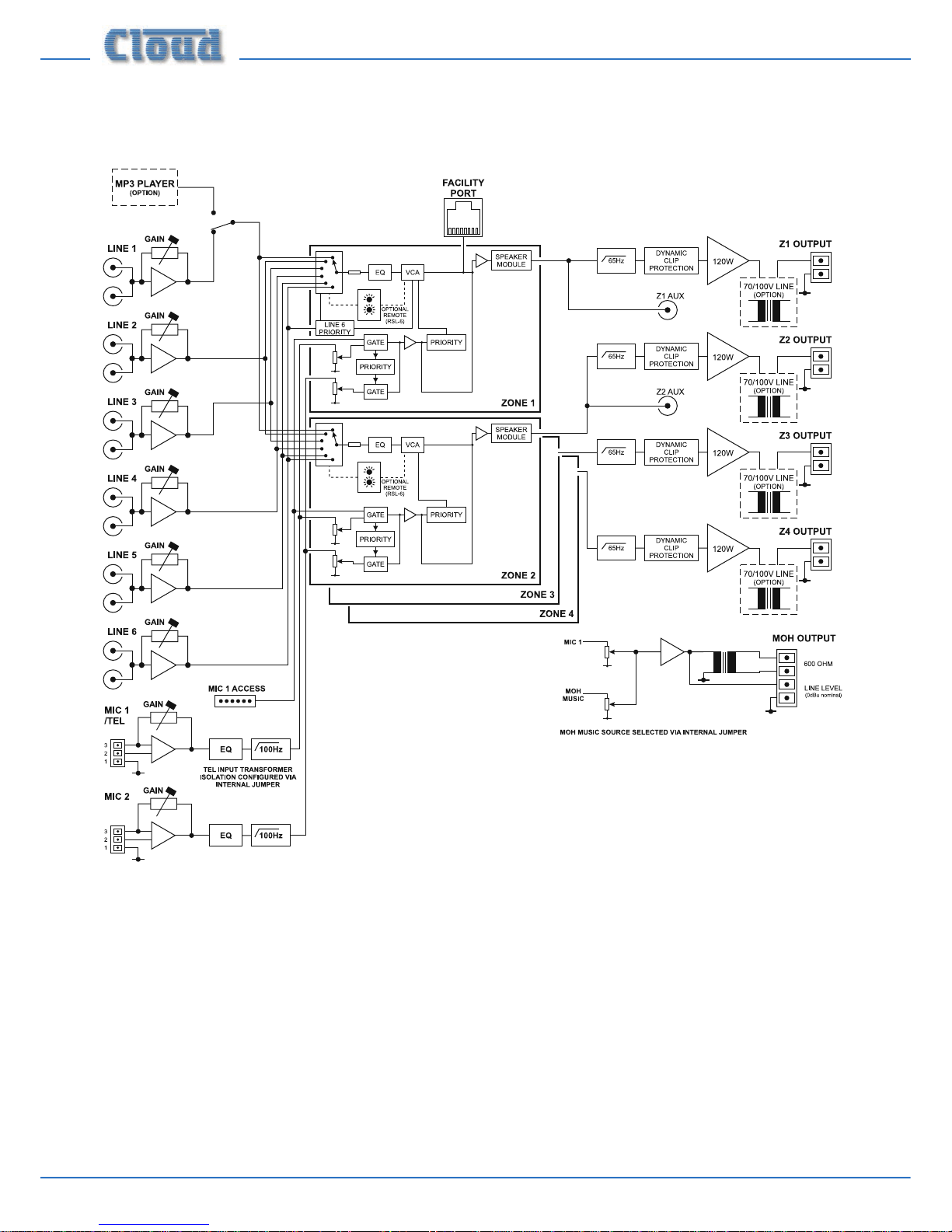
Block Diagram
The simplied block diagram above illustrates the basic signal architecture of the 46-120.
Page 11
46-120 Installation and User Guide V1.1 11
Front panel description
0
1010
10
0
-
dB
000
101010 101010
101010
000
---
dBdBdB
HFHFHFHF LFLFLFLF
1
2
3
4
5
6
1
2
3
4
5
6
1
2
3
4
5
6
1
2
3
4
5
6
CLIPCLIPCLIPCLIP
LEVEL LEVEL LEVELLEVEL
ZONE 4 MUSIC EQZONE 3 MUSIC EQZONE 2 MUSIC EQ
ZONE 1 MUSIC EQ
MIC 2 MIC 2 MIC 2 MIC 2
MIC 1 MIC 1 MIC 1 MIC 1
SOURCESOURCESOURCESOURCE
MUSIC LEVELMUSIC LEVELMUSIC LEVELMUSIC LEVEL
ZONE 1ZONE 2ZONE 3ZONE 4
PLAY
PAUSE
RANDOM
REPEAT
MEDIA PLAYER
USBMEMORY CARD
12046 MEDIA-
4 ZONE 120W INTEGRATED MIXER AMPLIFIER
0
1
3
913
14
16
10 11
15
9
5
12
6 6 6 6
5 5 5
4 3 4 3 4 3 4
12
7
917 18 19 20 8 8 8 89
2 2 21 1 1
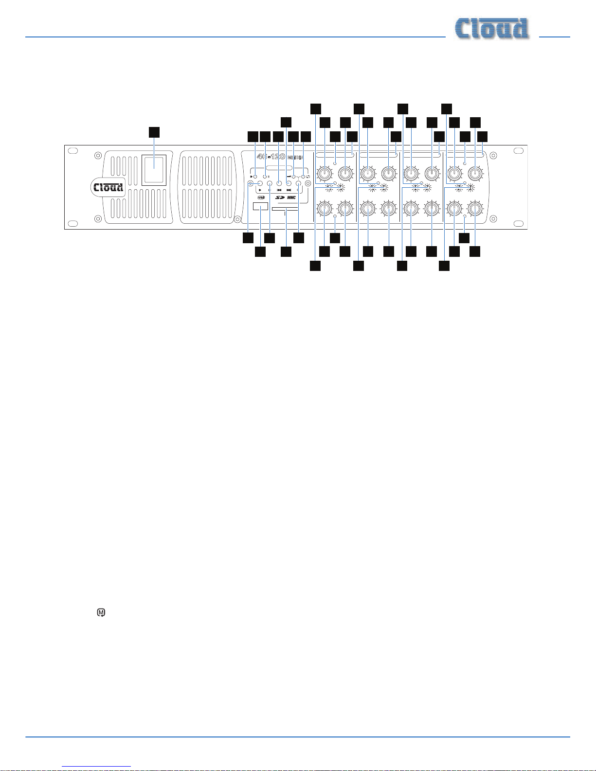
1. MUSIC SOURCE – 6-way rotary switch selecting which Line Input (LINE 1* to LINE 6) will be the music source
for each zone. See page 21.
2. MUSIC LEVEL – adjusts the music level in each zone. See page 21.
3. MIC 1 – adjusts the level of the microphone connected to the rear panel MIC 1/TEL input in each zone.
See page 21.
4. MIC 2 – as MIC 1, but controls level of MIC 2 input.
5. MUSIC EQ – two preset controls for adjusting HF/LF EQ in each zone. See page 22.
6. CLIP – per-zone red LEDs; illuminate when the output stage’s Dynamic Clip Limiter is active. This indicates that the
level is too high.
7. Power – rocker switch.
8. Zone idents – a space is provided above each zone’s controls for printed labels identifying the zone by name.
9. Fixing holes for security cover – prevents access to Zone EQ controls.
The following front panel items are only tted to the 46-120
MEDIA and 46-120TMEDIA:
10. USB port – Type ‘A’ USB 2.0 port for connection of memory device containing audio les.
11. MEMORY CARD – card slot, accepts SD or MMC memory cards containing audio les.
12. H – Play/Pause button: starts or pauses playback of current track/le.
13. A – Stop button: stops playback.
14. F – Previous button: moves playback point to start of previous track or le.
15. E – Next button: moves playback point to start of next track or le.
16.
– Mode button: selects Random and Repeat Modes.
17. PLAY – green LED, illuminates in PLAY mode.
18. PAUSE – green LED, illuminates in PAUSE mode.
19. RANDOM – green LED, illuminates when Random mode is selected.
20. REPEAT – green LED, illuminates when Repeat mode is selected.
*On the 46-120MEDIA and 46-120TMEDIA, switch position 1 will select the digital media player if it has been enabled by the rear panel LINE 1/MEDIA button
(see Rear Panel description).
Page 12

46-120 Installation and User Guide V1.112
Rear panel description
4 6
8 22 9
67 5
20
21
11
12
3 3 3 3 3 3
1 1 1 1 1 12
7 10 10 10 10 16 13 17 19 1814 15
1. LINE 1 to LINE 6 – 6 pairs of RCA (phono) sockets for connection of music sources. Inputs are stereo, summed
internally to mono. See page 14.
2. LINE 1/MEDIA – selects whether Music Source 1 is fed from LINE 1 inputs or the internal digital media player. This
push-button switch is only tted to models 46-120
MEDIA and 46-120TMEDIA.
3. GAIN – preset trim control for each line input, providing ±10 dB of gain adjustment for input level matching. See page
21.
4. MIC 1/TEL – balanced microphone input on 3-pin 3.5 mm-pitch screw-terminal connector. See page page 15.
This input should be used in conjunction with the ACCESS CONTACTS connector [7] for paging; it can also be
congured internally for use with a telephone system, See page 22.
5. MIC 2 – balanced input for a second microphone; 3-pin 3.5 mm-pitch screw-terminal connector.
6. GAIN – preset mic gain controls for MIC 1 and MIC 2, gain range 10 to 60 dB. See page 22.
7. HF and LF – preset mic EQ controls. See page 22.
8. ACCESS CONTACTS – 6-pin 3.5 mm-pitch screw-terminal connector for per-zone paging access by contact
closure. See page 16.
9. MUSIC CONTROL – 12-pin 5 mm-pitch screw terminal connector for connection of RL-1/RSL-6 remote control
plates. See page 17.
10. MUSIC CONTROL LEV & SRC – two push-button switches per zone which determine whether front panel music
source (SRC) and level (LEV) controls will remain active when remote control plates are connected. See page 17.
11. ZONE 1 FACILITY PORT – 8-pin RJ45 socket, for connection of LM-2 remote active modules, or as an auxiliary
input. See page 15.
12. AUX OUT – unbalanced line level outputs for Zone 1 and Zone 2 at 0 dBu. See page 20.
13. SPEAKER OUTPUTS – outputs for each zone on 8-pin 5 mm-pitch screw-terminal connector. See page 19.
These will be low impedance (min. load 4 ohms) on the 46-120 and 46-120
MEDIA models, and 70 V-line on the 46-120T
and 46-120TMEDIA models (as standard). If one or more CXL-46T transformers have been retrotted to a 46-120 or
46-120MEDIA, they may be either 100 V or 70 V-line. A checkbox area is provided below the connector for the installer
to indicate the conguration of each zone output.
14. MOH/UTILITY OUTPUT – an auxiliary output whose source can be set by internal jumpers. The output is available
as both unbalanced line level (0 dBu) and a galvanically-isolated output suitable for driving 600 ohm inputs, as found on
telephone system MOH (Music On Hold) inputs. See page 19.
15. MOH/UTILITY MIC 1 & MUSIC LEVEL – two pre-set controls, adjusting the level of the Mic 1 input and chosen
music source respectively at the Utility Output. See page 23.
Page 13

46-120 Installation and User Guide V1.1 13
16. MUSIC MUTE – 2-pin 5 mm-pitch screw terminal connector for connection of external emergency muting relay
(e.g., re control panel). See page 20.
17. REMOTE POWER DOWN – 2-pin 5 mm-pitch screw-terminal connector allowing the 46-120 to be put into
Standby Mode from external control systems. See page 20.
18. Mains – IEC receptacle for AC mains. See page 14.
19. FUSE – mains fuse. See page 14 for fuse details.
The following rear panel items are only present when the CDI-46 Digital Interface Card is tted:
20. CDPM/PM INPUT – RJ45 Cloud Digital Paging interface; PM Series* microphones (excluding the PM1) may be
connected here, using screened Cat 5 cable. See page 16 for more information.
21. ETHERNET INTERFACE – standard RJ45 network connector allowing the 46-120 to be controlled and congured
from external equipment using TCP/IP commands. It can also be used as an Ethernet-to-serial bridge to pass TCP/IP
commands from third-party control systems to the RS-232 connector [22].
22. RS232 – a 3-pin 3.5 mm-pitch screw-terminal connector providing a bi-directional RS-232 interface. This permits
control of the 46-120’s functions from an external system and can also transmit serial commands to third-party
equipment in response to Ethernet commands generated elsewhere.
* The earlier Cloud CDPM range of Paging Microphones is also compatible with this interface.
Page 14

46-120 Installation and User Guide V1.114
INSTALLATION
Hardware considerations
The 46-120 Mixer Amplier is built in a 2U-high 19” rack
mount enclosure. It is recommended that the 46-120 is
installed in a 19” rack wherever possible. The units are approx.
410 mm deep, but at least 500 mm of rack depth should be
available to allow for rear connectors and cabling.
The 46-120 uses thermostatically-controlled, variable speed
forced-air cooling. Depending on the ambient temperature
and signal levels, the fan (on the rear panel) may or may not
rotate; this is normal operation. The enclosure has air intake
slots in the front panel; ensure that these are not obstructed
once the unit is installed. Warmed air is expelled at the rear
of the unit by the fan. It is recommended that 1U blank panels
are tted in the rack above and below the 46-120; do not t
slotted ventilation panels as these defeat the action of forcedair cooling.
If the unit is to be used free-standing (i.e., not mounted in a
rack), the four feet supplied in the accessory pack should be
tted to the bottom of the chassis. These should be inserted
into the four 5 mm dia. holes clearly identiable in the corners
of the bottom panel, and secured by then inserting the plastic
rivets through the centre holes in the feet.
The choice of location will be dictated by the specics of the
system and building layout. It is recommended that wherever
possible, the 46-120 should be mounted adjacent to as many
of the music sources (CD players, music servers, TV receiver
boxes, etc.) as practical.
When deciding the Mixer Amplier’s location, bear in mind
that access to it (particularly the rear panel) will probably
be required from time to time even if a full complement
of remote controls is being tted as part of the system, as
certain adjustments can only be made on the unit itself.
Power Supply
The European version of the 46-120 operates on standard
230 V AC mains; an alternative version is available which
operates on 115 V AC. An IEC mains cable with a plug
appropriate for each country is supplied with the European
unit. The unit’s power consumption is 370 VA.
Fuses and ratings
The only externally-accessible fuse is an AC mains fuse on the
rear panel. Only replace a fuse with one of exactly the
same type. The table below gives the correct fuse types.
VERSION RATING FUSE TYPE
230 V 4 A 20 mm x 5 mm HBS T4A
115 V 8 A 20 mm x 5 mm HBS T8A
The fuseholder is of the “bayonet” type; press and twist the
holder anticlockwise to remove the fuse. If a replacement
fuse blows immediately, it indicates that the mixer amplier
has developed a fault, which should be referred to competent
service personnel.
Internally, two 20 mm x 5 mm fast-blow F8.0A fuses protect
each amplier channel (eight in total). These are service
components, and should not require attention. Failure of any
of these fuses indicates a fault condition, which should be
immediately referred to a competent technician or authorised
service centre.
System connections
Music sources
Connect the system’s various music sources to LINE 1
to LINE 6 as required. All line inputs offer unbalanced
connection for stereo sources on a pair of standard RCA
jacks (phono sockets). The sensitivity range available should
allow most standard items of audio equipment such as
computers/tablets, music servers and media receivers, etc., to
operate at a satisfactory level. Most equipment of this type
will have stereo unbalanced outputs, and as long as the source
equipment is adjacent to the Mixing Amplier, normal phonophono (or 3.5 mm jack-to-phono) leads can be used. Always
avoid using pre-made leads of an unnecessary length.
On 46-120
MEDIA and 46-120TMEDIA models, the media player
uses Music Input 1 (LINE 1); set the rear panel LINE 1/
MEDIA button OUT for the media player to be available to
the zones as Music Source 1. Press the button IN if the media
player is not in use; this permits LINE 1 inputs to be used in
the normal way.
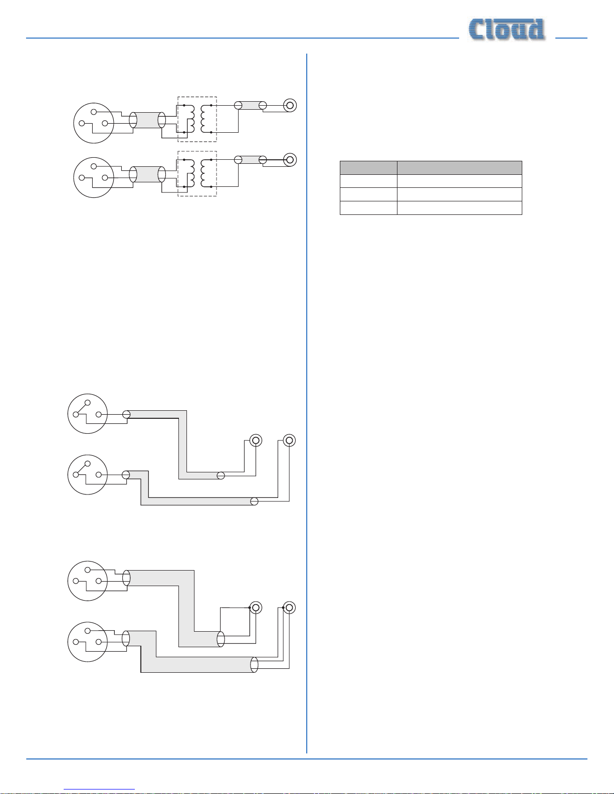
Mono and stereo sources:
The mixing section of the 46-120 is mono; the stereo line
inputs are summed internally. Stereo sources should be
connected in a normal stereo conguration, using both L
and R inputs. If connecting a mono source with only a single
output, it may be connected to either the left or the right
input.
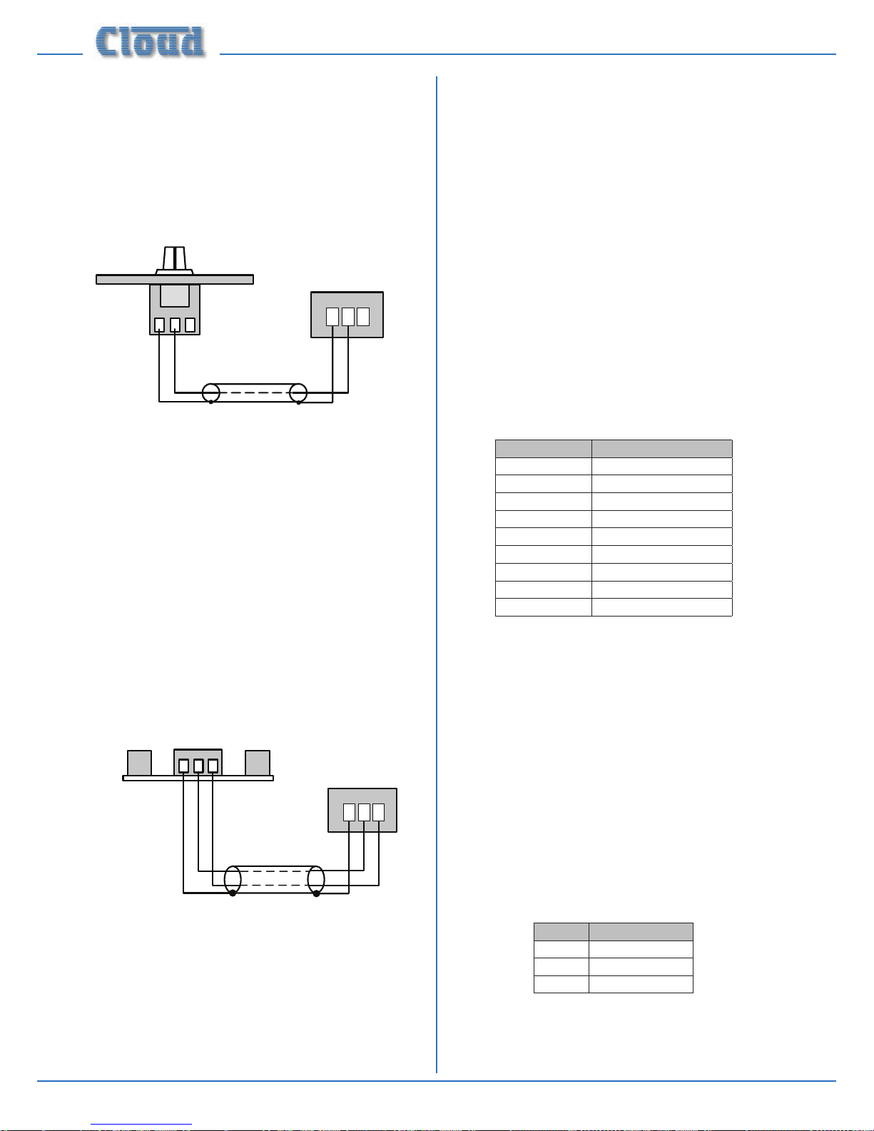
Balanced sources:
If it is necessary to connect an item of source equipment
with a balanced output to the 46-120, a balancing transformer
should ideally be inserted between the source and the
unbalanced input. Suitable audio transformers, which should
have a ratio of 1:1, are readily available from major audio
component suppliers. The transformer(s) should be mounted
as close to the 46-120 as practical, and housed in a screened
enclosure if they are not individually screened. The preferred
connection method is shown on the following page.
Page 15
46-120 Installation and User Guide V1.1 15
LEFT
+
-
SCN
Unbalanced
inputs
SCN
LEFT
+
-
SCN
Audio balancingtransformers
RIGHT
+
-
SCN
Unbalanced
inputs
SCN
RIGH
T
+
-
SCN
pi
n1ground
pi
n2hot
pi
n3cold
Balanced
outputs (XLRs):
12
3
12
3
If transformers are not available, a balanced source may feed
an unbalanced input directly as long as care is taken over how
the connections are made. A variety of design techniques are
in use to implement balanced outputs in audio equipment,
and some designs require different wiring protocols to others.
Installers are advised to check the manuals with each item
for guidance on how the outputs should be connected to an
unbalanced input.
However, the wiring methods shown below will work in a
large number of cases. If hum or other distortion is found to
result, try disconnecting the ‘cold’ leg of the balanced output
(pin 3 on XLRs).
1
2
3
Unbalanced
inputs
LEFT
RIGHT
+
+
SCN
SCN
+
+
SCN
SCN
When using single-core cable,
join ‘cold’ to screen at the
source
LEFT
RIGHT
pin1ground
pin2hot
pin3cold
Balanced outputs (XLRs):
1
2
3
Unbalanced
inputs
LEFT
RIGHT
+
+
-
-
SCN
SCN
+
+
-
-
SCN
SCN
When usingtwin-and-screen
cable, join ‘cold’toscreenat
36-50end
LEFT RIGH
T
pin1ground
pin2hot
pin3cold
Balanced outputs (XLRs):
1
2
3
1
2
3
Microphone input
Inputs MIC 1/TEL and MIC 2 are intended for the direct
connection of microphones. They are electronically balanced
and transformerless with an input impedance of greater than
2 kohms and optimised for use with microphones of 200 to
600 ohms impedance. The screw terminal input connectors
should be wired thus:
PIN CONNECTION
1 Screen
2 Signal ‘-‘ (cold)
3 Signal ‘+’ (hot)
Unbalanced microphones may be used by connecting pin 2
to pin 1 (cable screen) in the mating (male) screw-terminal
connector. 15 V phantom power is available, see page 22.
Either mic input may be routed to any of the zones in use,
at any level in each zone. Microphone priority may be set
so that any microphone announcements automatically reduce
the music level in that zone while the announcement is in
progress (see page 24 for more details.)
The MIC 1/TEL input may be recongured to accept an
audio input directly from a compatible telephone system.
This permits announcements to be made from some (or any)
internal telephone extensions in a building. Not all telephone
systems are suitable for this application, and the system
documentation should be consulted in detail to ensure
compatibility.
Internal jumpers J17A, J17B and J17C need to be moved
for this application. See page 30 for further information
regarding the internal jumpers. This inserts a transformer
in series with the input connector to provide full electrical
isolation from the telephone system. Note that the mic input
sensitivity is decreased by 10 dB when the transformer is
enabled, and this results in the mic gain control operating
over the range 0 dB to 40 dB.
The audio (or “paging”) output of the phone system should
be connected to the MIC 1/TEL input in the normal way.
The telephone input is optimised for connection to an output
of 600 ohms impedance; this should suit the majority of
telephone systems. Note that the front panel MIC 1 LEVEL
controls ([3] on page 11) are still operational.
Zone 1 Facility Port
Zone 1 of the mixer amplier is provided with a FACILITY
PORT in the form of a rear panel 8-way RJ45 connector.
The primary use of the Facility Port is for the connection
of an LM-2 remote active module, but it may also be used
as a general-purpose auxiliary balanced input (see page 26
for more information on this application). Note that audio
connected via the FACILITY PORT will only be available in
Zone 1, and no other.
The active modules operate from DC power supplied by the
46-120. The current consumed by each module is minimal and
Page 16

46-120 Installation and User Guide V1.116
in the vast majority of installations there will be no power
supply issues. See page 32 for more information about the
46-120’s DC power capabilities.
The pinout of the Facility Port connector is given in the table
below:
PIN USE Cat 5 CORE*
1 Audio ‘cold’ phase (-) White + Orange
2 Audio ‘hot’ phase (+) Orange
3 Priority VCA control White + Green
4 + 15 V Blue
5 0 V White + Blue
6 -15 V Green
7 Music level control (0 to 10 V) White + Brown
8 Music source select control (0 to 10 V) Brown
SCN Screen for system music controls Connector shell
* Standard wiring for pre-made cables
Please also refer to page 26 for further information
regarding installation of remote active input modules.
Connecting an LM-2 remote active module
The LM-2 should be connected to the FACILITY PORT
using screened Cat 5 cable. (Note that as the cable carries
analogue audio, only screened Cat 5 should be used.) All eight
cores are used. The LM-2 includes controls for local music
level and source selection, the wiring for these functions being
catered for on the Facility Port; thus it is not necessary to
make any connections to Zone 1’s MUSIC CONTROL
port.
The LM-2’s upper PCB is tted with an RJ45 connector
labelled OUTPUT. Connect this to the FACILITY PORT
of the relevant Zone using screened Cat 5 cable with screened
RJ45s at each end. Follow the colour coding shown in the
table above. The metal screening of the connectors should be
bonded to the screen of the cable. Full details can be found in
the LM-2 Installation Guide.
The second RJ45 connector on the LM-2, LINK, may be used
to “daisy-chain” additional LM-2s, thus allowing multiple input
modules to be installed at different locations in the Zone. See
the LM-2 Installation Guide for more details.
Before the LM-2’s music source and level controls will operate,
set the Zone 1 MUSIC CONTROL LEV and SRC pushbutton switches ([10] on page 12) to REMOTE (i.e., pressing
it in). In this setting, Zone 1’s front panel MUSIC LEVEL and
MUSIC SOURCE controls become inoperative. Sometimes
it is desirable to permit remote control of music level but
retain music source selection at the mixer amplier. In this
case, set only the LEV switch to REMOTE. This will render
the LM-2’s music source switch inoperative, and return source
selection to the 46-120’s front panel.
Paging system connections
Cloud PM Series paging microphones may be connected
directly to the 46-120 in two ways:
• via the Cloud Digital Paging interface ([20] at page 12)
– only available if the CDI-46 Digital Interface card is
tted.
• using the MIC 1/TEL input and ACCESS CONTACTS
connector.
Connecting PM4/4SA paging microphones
Cloud PM Series microphones are available in 4, 8, 12 or 16zone versions; the installer should be sure he/she understands
how paging zones correspond to mixer zones before
commencing wiring. Although the 46-120 only supports
a maximum of four zones, there is no technical reason to
prevent a PM microphone being used in a restricted manner.
Connection via the CDPM/PM port:
If a CDI-46 Digital Interface card is tted, the PM4 may be
simply connected to the CDPM/PM INPUT using screened
Cat 5 cable. No other connections are required; a PM4 will
be powered from the 46-120, but a PM4-SA will require an
external PSU. Full installation instructions are supplied with
the PM Series microphone and the CDI-46 card.
Connection via the Mic input
Two connections are required: the paging mic audio signal
should be connected to the MIC 1/TEL input ([4] on page
12) and the control cable to the 6-pin Zone ACCESS
CONTACTS port ([8] on page 12). The pinout of the
ACCESS CONTACTS port is given below:
PIN NO. FUNCTION
1 0 V
2 Zone 1
3 Zone 2
4 Zone 3
5 Zone 4
6 +12 V
Standard two-core screened audio cable should be used for
the audio signal, and stranded multicore cable with an overall
screen for the control cable.
Connections on the PM microphone are made via the
rear cable access glands and screw terminal blocks on the
internal PCB (TERM1, TERM2 and TERM8 in the case of
a PM4). Full connection details can be found in the PM Series
Installation and User Guide.
Page 17

46-120 Installation and User Guide V1.1 17
The diagram below shows the cable connections between a
PM4 and a 46-120.
TERM8
TERM2
H OT COLDG NDZ 1 Z 2 Z 3
Z 4
MIC 1/ TEL INPUT
Z 1 Z 2 Z 30 V
PM4 PAG ING MICROPH ONE
46-120
Z 5 Z 6 Z 7
Z 8
TERM1
0V
+ V
+ VZ 4
1 3
2
ACCESS CONTACTS
Note that the default factory setting is for all ACCESS
CONTACTS port inputs to be permanently enabled. In
order for the 46-120’s mic input to function correctly with
a paging mic, internal jumpers J10 to J13 (Zones 1 to 4
respectively) should be removed. See page 30 for jumper
locations.
For automatic music ducking during an announcement, the
internal jumper J6 should be set to ON (its factory default
setting). See page 24 for further information.
Connecting a PM1 paging microphone
The PM 1 is a simple, passive paging microphone suitable for
situations where announcements are always made to the
same zone(s). It can be connected directly to the 46-120
Mixer Amplier, the control cable being wired to the pin(s)
of the ACCESS CONTACTS connector corresponding
to the zone(s) in which announcements are required. Any or
all of the zones may be paralleled if multiple zones need to
operate from the PM1.
Either a single 2-pair individually-screened cable may be
used (this gives the neatest nish), or two separate standard
microphone cables. Connections on the PM1 are made via the
rear cable gland in the base and the screw terminal blocks on
the internal PCB (U2 and U3). Full connection details can be
found in the PM1 Installation and User Guide. Note that the
PM1 does not require DC power.
The following diagram shows the connections between a PM1
and a 46-120. Use of 2-pair cable is assumed; the same wiring
principle is adopted if separate cables are being used for audio
and control.
PAGING MIC INPUT
SCN COLD HOT N/O N/C GND
U2 AUDIO U3 ACCESS
ZONE ACCESS CONNECTOR
CONNECT TO
ZONE(S) IN USE
1 2 3
0V Z1 Z2 Z3 Z4 +V
46-120
PM1
Note that the default factory setting is for all ACCESS
CONTACTS port inputs to be permanently enabled. In
order for the 46-120’s mic input to function correctly with
a paging mic, internal jumpers J10 to J13 (Zones 1 to 4
respectively) should be removed. See page 30 for jumper
locations.
For automatic music ducking during an announcement, the
internal jumper J6 should be set to ON (its factory default
setting). See page 24 for further information.
Connecting OEM paging microphones
Other manufacturers’ paging microphones may be used
with the 46-120, provided they make the microphone signal
available at a suitable level (the 46-120’s mic gain adjustment
range should be sufcient to accommodate most types), and
that paging zone selection is by simple “contact closure-toground”. Providing these conditions are met, the connection
method described above for a Cloud PM4 using the Mic Input/
Access port method, or for the PM1 in the case of a singlezone mic, may be used.
Music control
Like many other Cloud products, the 46-120 allows remote
control of music level and source selection in each zone.
Cloud remote control plates from the RL-1 Series (music
level only) and RSL-6 Series (music level and source selection)
provide an elegant solution, though control via a DC voltage
from third-party systems is also possible (see page 26).
Both types of plate connect via the MUSIC CONTROL
port for the relevant zone (see [9] on page 12). Each zone
uses a 3-pin 5 mm-pitch screw terminal type connector. Please
refer to page 26 for additional information.
Page 18
46-120 Installation and User Guide V1.118
Connecting an RL-1 Series remote control plate
Wire the remote control plate as shown on the following
page. Either single-core screened or twin-and-screen cable
may be used; in the case of the latter, ignore one of the cores.
Maximum reliable cable run is 100 m.
1
2
3
REMOTE
SOURCE + LEVEL
123
REMOTE LEVEL CONTROL WIRING
RL-1
SINGLE-CORE SCREENED CABLE MAY BE USED
Before the RL-1 will operate, the zone’s MUSIC CONTROL
port must be enabled by setting the LEV push-button switch
([10] on page 12) to REMOTE (i.e., pressing it in). In this
setting, the zone’s front panel MUSIC LEVEL control
becomes inoperative, but the MUSIC SOURCE control is
still operative.
Connecting an RSL-6 Series remote control
plate
Wire the remote control plate as shown below. Twin-andscreen cable should be used. Maximum reliable cable run is
100 m.
123
REMOTE SOURCE & LEVEL CONTROL WIRING
RSL-6
USE TWO-CORE SCREENED CABLE
123
REMOTE
SOURCE + LEVEL
Before the RSL-6 will operate, the zone’s MUSIC CONTROL
port must be enabled by setting the adjacent push-button
switch ([12] on page 12) to REMOTE (i.e., pressing it in). In
this setting, both the zone’s front panel MUSIC LEVEL and
MUSIC SOURCE controls become inoperative.
CDI-46 digital interface
The optional CDI-46 Digital Interface card may be retrotted
to the 46-120 at any time. Full tting instructions are supplied
with the card itself.
The CDI-46 equips the 46-120 with the Cloud CDPM/PM
Digital Paging Interface, and also allows the Mixer Amplier’s
functions to be controlled from external systems using either
RS-232 serial data or TCP/IP commands via Ethernet.
The card includes a web browser interface via the Ethernet
port, allowing it to be congured using a simple Graphical
User Interface (GUI).
CDPM/PM interface
The Cloud CDPM/PM Digital Paging Interface (see [20] at
page 12) is an RJ45 socket allowing Cloud PM Series Paging
Microphones to be connected to the 46-120 using standard
screened Cat 5 cable. (Note that only screened Cat 5 should
be used.)
Use the standard Cat 5/RJ45 wiring convention as shown
below:
RJ45 PIN CAT5
1 Brown + White
2 White + Brown
3 Green + White
4 White + Blue
5 Blue + White
6 White + Green
7 Orange + White
8 White + Orange
RJ45 Shell Screen
Note that although multiple PM Series microphones may be
“daisy-chained” using the Digital Paging Interface, the 46-120
is only able to provide power for the “rst” microphone in
the chain (i.e., the one connected directly to the 46-120). Any
other microphones in the system must be powered by one or
more external PSUs; see the PM Series Installation Guide for
full details, and also page 32.
NOTE: The front panel MIC 1 level controls will affect the
paging level from a PM Series paging microphone connected
via the CDPM/PM port.
RS-232 connection
The CDI-46 card is tted with a bi-directional RS-232 port
(see [22] at page 12) on a 3-pin 3.5 mm-pitch screw
terminal connector. This should be wired as follows:
PIN FUNCTION
1 Gnd
2 Data Rx
3 Data Tx
The port operates at default rate of 9600 baud; the data
format is 8 bits, no parity, 1 stop bit. This can be changed using
the card’s web interface.
Page 19

46-120 Installation and User Guide V1.1 19
The CDI-46 Installation Guide supplied with the card includes
examples of the most commonly-used commands. A full
RS-232 protocol document is available at www.cloud.co.uk.
See also page 24.
Ethernet connection
The 46-120’s functions may also be controlled using TCP/IP
commands sent via the ETHERNET INTERFACE RJ45
connector (see [21] at page 12). Industry-standard Cat 5
cabling may be used.
The CDI-46 card can operate at either 10base-T or 100base-T
speeds, and auto-negotiates. The TCP/IP commands are the
same as the RS-232 command set; see the CDI-46 Installation
Guide and page 25 for more details.
The CDI-46 can also act as an Ethernet-to-serial bridge,
whereby the serial port transmits RS-232 commands to other
equipment on receipt of data received via the Ethernet port.
See also page 25.
Speaker outputs (Lo-Z)
The speaker output connector is an 8-pin, 5 mm-pitch screwterminal connector ([13] at page 12). Mating connectors
are supplied. The power amplier outputs for all four zones
are on this connector. If less than four zones are being used,
use as many of the mating 2-pin connectors as required.
Connect to speakers using pairs of terminals as shown in the
table:
Panel marking Connect to:
1 0V Zone 1 output ‘-‘
2 Z1 Zone 1 output ‘+‘
3 0V Zone 2 output ‘-‘
4 Z2 Zone 2 output ‘+‘
5 0V Zone 3 output ‘-‘
6 Z3 Zone 3 output ‘+‘
7 0V Zone 4 output ‘-‘
8 Z4 Zone 4 output ‘+‘
Each output stage is designed to drive into an impedance
of not less than 4 ohms. Check the impedance of the
loudspeaker(s) in use and, taking into account any series and/
or parallel wiring, ensure that the total load on each channel
is not less than 4 ohms.
100/70 V line operation
The 46-120 may be used with 100 V/70 V-line loudspeaker
systems by the use of Cloud CXL-46T transformers. These
are tted internally, one per zone. Any or all zones may be
converted, and may be used with 100 V and/or 70 V-line
operation as required.
The same output connector is used for both Lo-Z
and 100/70 V-line operation. It is not possible to
drive loudspeaker systems of the two types
simultaneously from the same zone output.
In the 46-120T and 46-120T
MEDIA model variants, four
CXL-46Ts are pre-installed at the factory, and wired for 70
V-line operation. This can be changed to 100 V-line operation
(per-output) if wished by moving an internal connector.
Alternatively, the 46-120 or 46-120MEDIA may be modied
for 100/70-V line operation by retrotting the transformers,
which are available from Cloud Electronics as an option.
Installation instructions can be found at page 28, and a
quick reference sheet is included with each transformer.
When using the 46-120 for 100/70 V-line operation, the
65 Hz high-pass lters in each zone to be used in this mode
should be enabled. See page 23 for full details.
A checkbox area is provided below the connector to allow
the installer to indicate the conguration of each zone.
MOH/Utility output
The MOH/UTILITY OUTPUT (MOH = Music On Hold)
is an auxiliary output which can be used for various purposes.
The source is selectable by internal jumpers. The output is
available both as a transformer-isolated 600 ohm feed and a
non-isolated line level feed.
A common application for the isolated output is to provide
continuous music-on-hold programme to a telephone system.
The line level output may be used to drive additional external
power ampliers, for example.
The output connector is a 4-pin 5 mm-pitch screw terminal
type ([14] at page 12), wired as follows:
PIN LABELLED USE
1 0V
LINE LEVEL Unbalanced 0 dBu output
2 +
3 -
600 OHM
ISOLATED
Isolated output for telephone
systems
4 +
Note that one pin of the line level output is connected
internally to 0 V.
The transformer-isolated output is suitable for connection to
a nominal 600 ohm load. The output level is nominally 0 dBu,
and the transformer provides full galvanic isolation from a
telephone system. It should be noted that a xed hi-pass lter
is tted in this output, to reduce bass frequencies when used
for this purpose.
Page 20

46-120 Installation and User Guide V1.120
1234
LINE
LEVEL
600 ohm
-
+
1234
600 ohm
To MOH input of
telephone system
MOH/Utility Output
OR
INDUCTION LOOP AMPLIFIER
LINE
LEVEL
Before using the MOH/Utility output with a telephone system,
it is recommended that the system manual is consulted to
check suitable audio levels and any other compatibility issues.
See page 23 for further details of the MOH/Utility output.
Auxiliary line outputs
In large zones, it may be necessary to use additional ampliers
to obtain the necessary power to drive a greater number of
loudspeakers, or to drive some loudspeaker types requiring
high power levels than the 120 W available from the 46-120’s
channels. To permit the connection of further ampliers (or
any other equipment), unbalanced outputs from the 46-120’s
pre-amplier sections for Zones 1 and 2 are available at the
rear panel phono (RCA) connectors labelled AUX OUT
Z1 & Z2.
All Zone1 and 2 controls and settings on the front and rear
panels (levels, source selection, priority settings, etc.) affect
the Auxiliary line outputs. However, note that their source is
pre the switchable 65 Hz high pass lters, thus any additional
ampliers connected at the AUX OUT outputs would need
to have hi-pass lters applied if they were being used to drive
100 V/70 V-line circuits.
Music Mute
External muting of music may be commanded through the
MUSIC MUTE connector. National or Local Authority
regulations governing installed audio systems may require
that normal programme material (i.e., music) should be muted
in an emergency, to ensure that any evacuation messages
are clearly audible. When active, it mutes the current music
source in all four zones, leaving the microphone inputs active.
The Music Mute input is on a 2-pin 5 mm-pitch screw-terminal
connector. It should be connected to the appropriate alarm
output on whichever building management system registers
the alarm (typically the Fire System). The alarm output must
be volt-free; if no such output is available, an intermediate
relay or other isolation device must be installed between the
alarm output and the Music Mute input.
The Mute input can be set to operate on either normally
open (N/O) or normally closed (N/C) contacts via internal
jumper J5 (see page 30). The factory default setting is N/O,
thus requiring a short-circuit to be applied across the two
pins of the connector for muting to occur.
NOTE: The rear panel line input sub-board and Facility Port
sub-board will need to be removed (undo M3 screws on rear
panel) to gain access to jumper J5.
1 2
MUSIC MUTE
INPUT
RELAY
NORMALLY OPEN (NO)
CONNECTION
Remote Power Down
The 46-120 may be powered-down remotely, typically from an
external control system. A 2-pin, 5 mm-pitch screw-terminal
connector, REMOTE POWER DOWN ([17] at page 12)
is provided for this purpose. A short-circuit applied across the
pins will power the 46-120 down; thus wiring this connector
to the contacts of an external relay (typically one within a
control processor) is all that is required to implement this
feature. The short-circuit must be kept applied to maintain
the 46-120 in an OFF state; on removing the short-circuit, the
46-120 immediately powers-up again.
Page 21

46-120 Installation and User Guide V1.1 21
SETTING UP & OPERATION
Music Inputs
Gain & level
To avoid dramatic changes in volume when switching between
sources, the 46-120’s music inputs are provided with preset
gain trim controls ([3] on page 11). These vary the input
sensitivity from -12 dBu (195 mV) to +8 dBu (2.0 V). When
setting the system up, play audio from all the sources in use
and listen to them one at a time in a convenient zone (ideally
that in which the mixer is located) at a reasonable volume.
Taking a source of “average” volume as the reference, the gain
controls of the others should be adjusted so that there is no
appreciable difference in volume between any of the sources.
(With a typical music source, setting the gain on its channel
to mid-way is a good starting point.) Note that consideration
may need to be given to the type of programme in use,
particularly if the sources include TV sound.
In normal operation, the music level in each primary zone
is set with the MUSIC LEVEL control on the front panel
([2] on page 11). This control will not be operative if the
corresponding rear panel MUSIC CONTROL LEV pushbutton is set to REMOTE. The music level at the MOH/Utility
output is set with the rear panel MOH/UTILITY MUSIC
LEVEL preset control ([15] on page 12).
Note that the setting of the music level has no effect on
microphone volume.
Local/remote control
If a zone is to have its music level and/or source controlled
remotely – typically by an RL-1 or RSL-6 Series remote control
plate - the corresponding rear panel MUSIC CONTROL
push-button(s) must be set to REMOTE (button in) for the
remote controls to be operative and for the corresponding
front panel controls to be disabled. Zones without such plates
should be set to FRONT PANEL (button out).
The 46-120 features separate MUSIC CONTROL buttons
for assigning control of music source and level in each zone
to a remote control plate. The four LEV buttons determine
whether music level will be controlled from the 46-120’s
front panel or from a remote location, and should be set to
REMOTE for zones in which an RL-1 or RSL-6 Series plate
is installed. The corresponding front panel MUSIC LEVEL
controls will be disabled. The four SRC buttons determine
whether music source selection will be controlled from the
46-120’s front panel or from a remote location, and should be
set to REMOTE for zones in which an RSL-6 Series plate is
installed. The corresponding front panel MUSIC SOURCE
controls will be disabled.
Note that the 46-120 supports additional
methods of remote control of music level and
source. These are:
• use of an LM-2 remote active module connected to the
ZONE 1 FACILITY PORT (applicable to Zone 1 only)
• RS-232 serial or TCP/IP control from external control
systems via a CDI-46 Digital Interface card.
In both cases, the MUSIC CONTROL SRC and LEV
buttons for the relevant zone(s) should be set to REMOTE
for correct operation and for the front panel controls to be
disabled.
Note that independent remote control of music level or
source selection in areas fed by the Utility output is not
possible.
46-120MEDIA digital media player
This section of the manual applies to models
46-120MEDIA and 46-120TMEDIA only.
MEDIA versions of the 46-120 include an integral
digital audio player, which can play audio recorded as WMA
or MP3 les from either USB memory devices or SD cards
plugged into their respective sockets on the front panel [10]
and [11].
A standard set of “transport” controls is provided on the
front panel to play, stop, pause, etc., programme material.
The stereo audio output of the media player is mixed to (L+R)
mono and routed internally via the LINE 1/MEDIA switch
([2] at page 12) to Line Input 1. Thus to route the media
player to one or more zones, the rear panel switch must be
set to MEDIA (button OUT), and the front panel MUSIC
SOURCE switch set to 1.
Compatible media
• USB: USB 2.0-compatible memory devices.
• SD: SD cards up to 4 GB capacity, or SDHC cards up
to 32 GB. MMC cards of the same capacity are also
compatible.
Filing systems supported are FAT16 or FAT32.
File types and rates supported
The 46-120MEDIA versions will replay audio les recorded in
either WMA or MP3 formats, as follows:
• WMA: bitrates from 32 kpbs to 384 kbps
• MP3: MPEG 1/2/2.5, layer 2 or 3 decoding at bit rates
from 32 kpbs to 384 kpbs, including VBR.
Sample rates supported are: 8 kHz, 11.025 kHz, 12 kHz,
16 kHz, 22.05 kHz, 24 kHz, 32 kHz, 44.1 kHz and 48 kHz
Both types of audio le may be present on the memory
device; the media player will not differentiate between them
in any way. The les may be in the root directory of the
memory, or in folders, or folders within folders. When the
memory device is plugged in, the media player will scan it and
identify all compatible les in all folder locations, and make
them available for playing. Only one memory device at a time
(USB device or SD card) may be connected. Note that it is
not possible to create a playlist from the 46-120
MEDIA’s front
panel controls.
Page 22

46-120 Installation and User Guide V1.122
Basic operation
The front panel transport controls operate in a similar
manner to the standard controls on, say, a CD player.
Plugging a memory device into one of the front panel sockets
will activate the player and after a short delay, the player will
enter PLAY mode, conrmed by the illumination of the PLAY
LED ([17] at page 11). In Normal Mode (see below), the
rst track played is the one whose lename starts with the
lowest numeric/alpha characters.
The track playing may be momentarily paused by pressing
the H button [12]; the PLAY LED goes out and the PAUSE
LED [18] illuminates to indicate this. Play is resumed from
the point at which it was paused by a further press of the H
button. The track may be stopped from either Play or Pause
modes by pressing the A button [13]; both LEDs go off.
The next or previous track may be selected for immediate
play by pressing the E or F button respectively. These
buttons operate in any transport mode. (Unlike a CD player,
the F button will cause the play point to jump to the start of
the previous track, not that of the current one).
Three operational modes are available, selected by the
MODE button [16] (marked with the symbol
). Successive
presses of the MODE button step through the modes:
The REPEAT and RANDOM LEDs [20] and [19] illuminate
to conrm these two particular modes. Both LEDs off
indicates Normal Mode.
Normal Mode
In Normal Mode, the media player plays through all the
available audio les in order of lename, regardless of which
folder they are in on the memory device.
Numeric characters are given higher priority than alphabetic
ones, so audio tracks whose lenames begin with numbers
will be played rst. This makes it very simple to pre-ordain
track playing order; if the tracks are given lenames beginning
“01”, “02”, etc., they will always be played in that order in
Normal Mode.
Random Mode
In Random Mode, the next track to be played is selected at
random from all the tracks available on the memory device.
Note that this is not the same as the “Shufe” mode found
on portable MP3 players - a fresh random selection from all
available tracks is made at the end of each track, and thus
there is a possibility that the same track may be played twice
in succession.
Repeat Mode
If Repeat Mode is enabled while a track is playing, the track
will be repeated when it has nished. This repetition will
continue until Repeat Mode is cancelled. Repeat Mode may
also be selected from Stop Mode; the next track played when
H is pressed will then repeat until Repeat Mode is cancelled.
Note that Repeat Mode only applies to individual tracks; it is
not possible to repeat a sequence of tracks.
Microphone inputs
Phantom power
Both microphone inputs have 15 V phantom power available.
This will be adequate to power a wide range of condenser
microphones. (Some “studio quality” mics may require a
higher phantom voltage and thus necessitate an external
PSU.) To enable phantom power at a mic input, internal PCB
jumpers J1 (MIC 1/TEL) or J2 (MIC 2) should be moved to
their ON position. See page 30 for jumper location.
Phantom power should NOT be enabled if dynamic
microphones are to be used.
Gain & level
Both m i cr o p h o n e i n p u t s are provided with a rear panel
preset gain control ([3] on page 12). A wide range of gain
(10 to 50 dB) is available and there should be no problem in
obtaining a satisfactory level from any normal microphone.
The GAIN controls should be adjusted by speaking normally
into a microphone of the correct type. Turn the corresponding
front panel MIC LEVEL control up to maximum and listen
in a convenient zone; the rear panel gain control should be
carefully advanced until the mic volume is as loud as it is ever
likely to be needed, and then reduced slightly. There should be
no audible distortion. The use to which the microphone is to
be put should be borne in mind – karaoke is more likely to
overload the mic preamplier than spoken announcements, if
the gain is not set correctly.
In normal operation, the mic level in each primary zone is
set with the MIC LEVEL controls on the front panel ([3]
and [4] on page 11). The mic level at the Utility output is
set with the rear panel MOH/UTILITY MUSIC LEVEL
preset control ([15] on page 12).
EQ
Each mic input has associated HF and LF EQ controls ([7] on
page 12) These provide 10 dB of cut or boost at 5 kHz and
100 Hz respectively and should be adjusted by listening to
achieve a clear mic sound. Again, the application should be
borne in mind when making adjustments.
High-pass lter
The mic input has a xed 100 Hz high-pass lter to remove
the lowest frequencies. This helps to reduce the effects of
breath blasts and microphone handling noise. The lter is
always in circuit.
Use of Mic 1 with a telephone system
The MIC 1/TEL input on the 46-120 may be recongured to
accept an audio input directly from a compatible telephone
Page 23

46-120 Installation and User Guide V1.1 23
system. This permits announcements to be made from some
(or any) internal telephone extensions in a building. Not
all telephone systems are suitable for this application, and
the system documentation should be consulted in detail to
ensure compatibility.
Internal jumpers J17A, J17B and J17C need to be moved
for this application. See page 30 for further information
regarding the internal jumpers. This inserts a transformer
in series with the input connector to provide full electrical
isolation from the telephone system. Note that the mic input
sensitivity is decreased by 10 dB when the transformer is
enabled, and this results in the mic gain control operating
over the range 0 dB to 40 dB.
The audio (or “paging”) output of the phone system should
be connected to the MIC 1/TEL input in the normal way. The
telephone input is optimised for connection to a 600 ohm
output; this should suit the majority of telephone systems.
Note that the front panel MIC 1 LEVEL controls [3] are
still operational.
Zone and MOH/Utility outputs
In normal operation, the music level in each zone will be
set by the front panel MUSIC LEVEL control, or by a
corresponding control on a remote plate or module (or other
control system). The music level at the Utility/MOH output
will be set by the rear panel MOH/UTILITY MUSIC
LEVEL preset control.
EQ
The various zones in a building often have different acoustic
properties, and may also have different models of loudspeaker
installed. The 46-120 is tted with per-zone HF and LF EQ
adjustments for the music signal ([5] on page 11) to enable
the audio frequency response to be best matched to each
zone’s acoustics. The controls should be adjusted by listening;
up to 10 dB of cut or boost at 10 kHz (HF) and 50 Hz (LF) is
available. Note that these EQ adjustments do not affect the
frequency response of the microphone signal.
After the EQ has been adjusted during system commissioning,
the EQ presets may be made inaccessible by tting the
security cover (one supplied with each Mixer Amplier). See
page 29 for tting instructions.
MOH/Utility output settings
The MOH/UTILITY output of the 46-120 can be used
for various purposes: a common application is to drive
loudspeakers (using additional power ampliers) in secondary
areas such as corridors, lobbies or toilets, where there is no
necessity to make frequent alterations to the music source
or level.
Eight source options are available for the signal at the MOH/
Utility output, selected by internal jumper J16. This jumper is
in the form of a 2x8-way header, with a link being positioned
on one pair of pins only. The options are:
• The output is always fed with the music signal connected
to any one of LINE 1 to LINE 6. When in use with a
telephone system as an MOH source, it is generally more
desirable for the music source to remain constant; these
options are available for this purpose.
• The output always follows the music source selection
made for Zone 1 (either on the front panel or via remote
control). The MUSIC LEVEL control for Zone 1 does
not affect the level at the MOH/Utility output. This option
is the factory default setting.
• The output is always fed with the output of the media
player. The rear panel LINE 1/MEDIA switch setting is not
relevant, and the media player may be used simultaneously
as Music Source 1, or not, as wished. This option is only
operative on models 46-120
MEDIA and 46-120TMEDIA.
See page 30 for locations and settings of PCB jumpers.
The signal at the MOH/UTILITY output may be any
required mix of the selected music signal and the microphone
signal connected at the MIC 1/TEL input, and is set using the
rear panel presets MOH/UTILITY MIC 1 LEVEL control
and MUSIC LEVEL (see [15] at page 12). Each signal is
effectively ‘off’ with the preset control in its fully anticlockwise
position. Note that the signal at this output is NOT altered by
any front panel MUSIC LEVEL or MIC LEVEL controls,
or any front panel MUSIC EQ preset adjustments.
The MOH/UTILITY MIC 1 LEVEL control
should be turned fully down if the output is to be
used for MOH with a telephone system, otherwise
paging announcements will be heard by telephone
callers.
If Zone 1 is selected as the MOH/Utility source (the factory
default setting), and Line 6 Priority is enabled (see page 24),
the MOH/Utility output will switch to Line 6 along with
Zone 1 output if the input becomes active.
High-pass lters
When the 46-120 is used to drive 70/100 V-line loudspeaker
systems via internally-tted CXL-46T transformers (as in the
46-120T and 46-120TMEDIA), there is a risk of transformer
saturation at high levels and low frequencies. To prevent
this, each of the 46-120’s four channels is provided with a
switchable 65 Hz high-pass lter. These should be enabled for
any channels being used to drive 70/100 V-line systems.
The lters are enabled by moving internal PCB jumpers J3
(Zone 1), J4 (Zone 2), J8 (Zone 3) and/or J9 (Zone 4). See
page 30 for locations of PCB jumpers.
In models 46-120T and 46-120T
MEDIA, the jumpers are set at
the factory in the ‘ON’ position (lters enabled) for all zones.
Page 24

46-120 Installation and User Guide V1.124
Priorities
The 46-120 offers several options for determining what
happens to music signals when announcements are made.
Mic-over-Music priority
Fully automatic, voice operated priority is available for the mic
inputs. This is selected by internal PCB jumper J6, which should
be set ON (the factory default setting) to enable priority
operation. When enabled, all music signals will attenuate by
approximately 30 dB when the microphone is used (a process
often referred to as “ducking”); after the announcement, the
music signals will restore smoothly to their former level, over
a period of approx. 0.5 s.
The Priority setting applies to both microphone inputs, and a
signal at either MIC 1/TEL or MIC 2 input will initiate ducking.
If Mic-over-Music Priority is not enabled, microphone inputs
will be mixed with the selected music signal in each zone at a
level determined solely by the front panel controls.
See page 30 for location of the internal jumpers.
Line 6 priority
It may sometimes be necessary for one music input to have
priority over all the others; for example, a jukebox in a bar,
or a digital sound store programmed to make automatic
announcements in a public space. Input LINE 6 may be set
to have priority in Zone 1 over whichever source is selected
for the zone by its MUSIC SOURCE control. This priority
is set by moving internal jumpers J14A and J14B to the ‘ON’
position. (The default setting is ‘OFF’.)
When the priority is selected, a signal present at Line 6 will
force Zone 1’s source selection to that input; when the signal
disappears, the previously-selected source will be restored
over the time constant selected by J15 (3, 6 or 12 s).
Note that on the 46-120, Line 6 Priority is only effective in
Zone 1. During Line 6 Priority operation, Zones 2, 3 and 4
will continue to output their currently-selected music source.
See page 30 for location of the internal jumpers.
Mic-over-Facility Port priority
If an LM-2 remote active module is in use in Zone 1, it is
possible to give a microphone connected at the 46-120
itself (at MIC 1/TEL or MIC 2) priority over input sources
connected at the module. This might be desirable in function
rooms, for example, where building-wide announcements may
need to interrupt any local use.
This priority is set by internal PCB jumper J7. The default
setting is ‘OFF’; in this position microphones or other sources
connected at remote input modules will be autonomous
and will not be overridden by announcements made via the
mixer’s mic inputs. Setting J7 to ‘ON’ will give priority to
Mic 1 or Mic 2. The release time following an announcement
is approx. 0.5 s.
Note that this priority is independent of the local MIC
PRIORITY function which can be selected on the remote
module.
Control
CDI-46 digital interface
The optional CDI-46 Digital Interface card permits the
46-120 to be controlled by either RS-232 serial data or
TCP/IP commands via an Ethernet connection. Abridged
tting instructions can be found at page 27, and connection
information at page 18.
Full operating instructions for the CDI-46 are
included with the card itself. The following manual
sections are intended to give a brief overview of
the card’s remote control features.
Remote control via RS-232
The RS-232 serial port’s default parameters are as follows:
• Baud rate: 9600
• Word length: 8 bits
• Stop bits: 1
• Parity: none
The port is bi-directional.
The port parameters may be altered using the web browser
GUI accessed through the Ethernet port (see following page).
Examples of some basic commands are given below:
COMMAND ASCII NOTES
Select source y for
Zone x
<Zx.MU,Sy/>
1≤x≤4, 1≤y≤6
Increase music level
in Zone x by n dB
<Zx.MU,LUn/>
1≤x≤4
Decrease music level
in Zone x by n dB
<Zx.MU,LDn/>
1≤x≤4
Mute Mic p in Zone x
<Zx.Mp,M/>
1≤x≤4, p=1 or 2
Unmute Mic p in
Zone x
<Zx.Mp,O/>
1≤x≤4, p=1 or 2
Enable paging in
Zones 2 & 3
<M1,PAOXXO/>
X=route paging mic,
O=don’t route; position
in string denes Zone
Release paging
<M1,PR/>
Expanded command information is included in the CDI-46
Installation Guide and a full RS-232 Protocol document is
available from www.cloud.co.uk.
Page 25

46-120 Installation and User Guide V1.1 25
Remote control via Ethernet
The card includes a web server which will generate GUI pages
on a browser logged in to the CDI-46’s IP address. Access
is password-protected. Even though the CDI-46 has DHCP
functionality, we recommend that it should be set with a static
IP address (i.e., DHCP disabled) or uses a reserved address
on your routing hardware. It will then have a xed IP address
on the network for other devices to browse to. Ensure that a
suitable IP address is reserved on the network to which you
intend to connect the device. If the CDI-46 changes IP address,
client security settings will not be preserved. (Installers may
need to consult the IT Manager of the installation premises
for guidance.)
As well as the browser control from the GUI, serial commands
may be sent to the 46-120 via the CDI-46 card in TCP/IP
format through the Ethernet port. This allows external
Ethernet-equipped control systems to be interfaced to the
46-120 using standard IT industry infrastructures.
The same serial protocol used with the RS-232 port is valid
for the Ethernet port.
Ethernet-to-Serial bridge
The CDI-46 card can be congured to accept incoming ASCII
commands via the Ethernet port and re-transmit these as
serial data from the RS-232 port. These commands can be
used to provide serial control of external devices.
Auto Power Down
The 46-120 can be made more energy-efcient by enabling
its Auto Power-Down feature. This monitors the signal level
in each zone, and after an installer-determined idle time, will
put the power amplier stage into a standby state, minimising
power consumption. If a signal is detected while the channel is
in standby, the amplier stage is re-powered and operational
within 40 ms.
Selection of idle time is by setting the internal PCB jumpers
J18A, J18B and J18C. The time is denable in 15 minute
increments from zero (i.e., Auto Power Down is disabled) to
105 minutes.
The three jumpers use binary weighting to set the idle time;
J18A is the MSB, J18C the LSB. The table below summarises
the required settings for each idle time value.
Idle time J18A J18B J18C
No APD (Disabled) OFF OFF OFF
15 mins OFF OFF ON
30 mins OFF ON OFF
45 mins OFF ON ON
60 mins ON OFF OFF
75 mins ON OFF ON
90 mins ON ON OFF
105 mins ON ON ON
See page 30 for details of jumper locations.
Page 26

46-120 Installation and User Guide V1.126
OPTIONS AND ADDITIONAL
INFORMATION
LM-2 remote active module – general
considerations
Cloud LM-2 remote input modules are available in three
form factors, to t double-gang UK, American or German
DIN-standard electrical back boxes. Back boxes of either
the recessed type or surface-mounting type may be used,
providing they are at least 35 mm deep.
The modules should be connected to the ZONE 1
FACILITY PORT using screened Cat 5 cable as described
at page 15. The OUTPUT connector on the module and
the ZONE 1 FACILITY PORT on the mixer are both
screened RJ45 sockets.
Great care must be taken when connecting active input
modules; power is derived from the mixer and some wiring
errors may cause failure of the mixer. Please check all wiring
before testing the system.
Connecting multiple LM-2s
It may be desirable to connect local microphones or music
sources at more than one location in Zone 1 (which may be
a large function room, for example). LM-2 input modules may
be “daisy-chained” using their second LINK RJ45 connectors
to achieve this.
Remember to consider the current drawn by any additional
input modules – see page 32 for details of current
consumption and PSU capability.
In-zone sources
An LM-2 module has an input for a dynamic microphone on
an XLR socket and a stereo line input on both two phono
sockets and a 3-pin 3.5 mm jack socket. The mic and line
inputs have separate level controls and all signals are mixed to
mono for routing to the 46-120.
If multiple LM-2s are “daisy-chained” as described above, the
mono sums from all modules are summed together.
The microphone input may be assigned priority over both
the line inputs and the music source selected for Zone 1 on
the 46-120 by pressing the module’s MUSIC PRIORITY
button. See the LM-2 Installation Guide for full details of this
feature.
The Facility Port input circuitry includes a Noise Gate to
minimise residual noise when the microphone is not in use or
during gaps in music programme.
In-zone remote control
In addition to the mic and line inputs, LM-2 modules also have
controls for music level and music source selection; these
function in an identical manner to RSL-6 remote control
plates. No connection to the 46-120’s MUSIC CONTROL
ports is required, all control is via the single screened
Cat 5 cable. However, for the remote controls to operate, it is
necessary to set the MUSIC CONTROL SRC and/or LVL
buttons (as required) for Zone 1 to REMOTE.
If multiple LM-2s are “daisy-chained”, only one may have its
music controls operative; see the LM-2 Installation Guide for
full details.
Using the Facility Port as an auxiliary
zone input
The Facility Port provides a balanced audio input. If a port
is not connected to an LM-2 remote input module, it may
be used as a direct input to the zone from other equipment
forming part of the system (for example, a permanently
installed DJ mixer which only ever needs to feed its output to
that particular zone).
Wire an external balanced source to the facility port as
shown below:
1
8
7
6
5
4
3
2
132
BALANCED
OUTPUT(e.g.
XLR)
hot (+)
hot (+)
cold (-)
cold (-)
1
8
1
8
1
8
42-120 ZONE 1
FACILITY PORT (RJ45)
An unbalanced source may also be connected; the use of
balancing transformers is recommended.
RL-1 and RSL-6 Series remote
control plates – general
considerations
Cloud RL-1 Series and RSL-6 Series remote control plates
are available in three form factors, two t single-gang UK or
American electrical back boxes respectively; the third is a
50 x 50 mm “Media” module, suitable for “Euro-module”
mounting frames available in most European countries. Back
boxes of either the recessed type or surface-mounting type
may be used, providing they are at least 25 mm deep.
The plates should be connected to the MUSIC CONTROL
port of the relevant zone using single- or twin-core screened
cable as described at page 18. The plate terminations are
conventional screw terminals and the MUSIC CONTROL
port on the mixer is a 3-pin 5 mm-pitch screw terminal connector.
The remote control plates are passive and thus do not draw
any current from the mixer.
Page 27
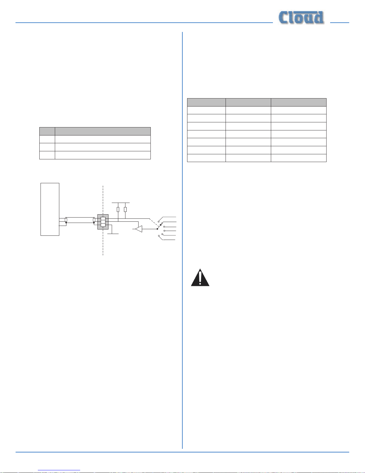
46-120 Installation and User Guide V1.1 27
Control of music source and level via
external DC
It may be necessary in some installations to adjust the music
level and select music source in one or more zones from
an external control system (e.g., Crestron, AMX, etc.) If the
MUSIC CONTROL ports are not required for RL-1/RSL-6
Series remote control plates, they may be used to receive DC
voltages from the external system to effect these adjustments.
Both music source selection and level can be controlled over
their full ranges with a DC voltage of 0 to +10 V. The pinout
of the MUSIC CONTROL port is as follows:
PIN USE
1 0 V ref.
2 Music level control (0 to +10 V)
3 Music source selection (0 to +10 V)
REMOTE
SOURCE+LEVEL
PORT
1
2
3
+15 V
0 V
MUSIC VCA
MUSIC SOURCE
SELECT
4k7
15k
CONTROL
SYSTEM
0V REF
LEVELCONTROL
SOURCECONTROL
42-120
NOTE: If the control voltage source is not isolated from
the power earth, there is a small risk of creating a ‘ground
loop’ by linking the mixing amplier technical ground (0 V)
to the ground (0 V) of the equipment supplying the control
voltages. To minimise this risk, we suggest that all pieces of
equipment be in close proximity, and supplied from the same
power outlet.
Music level
Music level in a zone may be varied over its full range by
applying a DC voltage of between 0 and +10 V to pin 2, the 0 V
reference being connected to Pin 1. 0 V on pin 2 corresponds
to maximum level and +10 V will produce 60 dB of attenuation.
The rate of attenuation is approximately 165 mV/dB.
Note that there is an internal 4k7 “pull-up” resistor between
pin 2 and the internal +15 V rail. If pin 2 is left “oating”, this
pull-up will result in full attenuation. The output impedance of
the control voltage source should be low enough to overcome
the effect of this resistor.
Music source
Music source for a zone may be controlled by applying various
DC voltages of between 0 and +10 V to pin 3, the 0 V reference
being connected to pin 1. 0 V at pin 3 will select Line input
6 and between +7.5 and +9 V will select Line input 1. The
other line inputs will be selected with intermediate voltages.
Taking pin 3 above +9 V will deselect all inputs, making the
zone effectively ‘off’ for music.
The table below lists the DC voltages required at pin 3 to
select each line input. The third column is the value of a
resistor which should be connected between pins 1 and 3 to
permanently ‘force’ a zone to a particular line input.
INPUT DC VOLTAGE RESISTOR VALUE
OFF >+9.0 V
Line 1/Media +7.5 V 16k
Line 2 +6.0 V 11k
Line 3 +4.5 V 6k8
Line 4 +3.0 V 3k9
Line 5 +1.5 V 1k8
Line 6 0 V short-circuit
Note that there is an internal 15k “pull-up” resistor between
pin 3 and the internal +15 V rail. If pin 3 is left “oating”, this
pull-up will cause ‘OFF’ to be selected. The output impedance
of the control voltage source should be low enough to
overcome the effect of this resistor.
Fitting the CDI-46 digital interface
Full tting and set-up instructions are provided in the
Installation Guide included with the optional CDI-46 Digital
Interface card.
Below is an abridged set of tting instructions:
Note that some main PCB jumpers will become
inaccessible once the CDI-46 card is tted.
Installers are advised to check that all jumpers are
in their required positions before tting this card.
1. Disconnect the 46-120 from the AC mains.
2. Remove the top cover (10 screws) and orient the unit
with the rear panel towards you.
3. Unplug the 20-pin ribbon cable from CON13 on the line
input sub-board.
4. Remove two M3 screws from the main PCB; these are
behind the line input sub-board, adjacent to CON21 and
CON23.
5. Replace the screws with the M3x15 hex pillars supplied
with the card.
6. Remove the two jumpers from the header CON21 and
four from header CON23 (both on the main PCB).
7. Locate the CDI-46 card below the line input sub-board
so that the three connectors and two tapped M3 holes
align with the empty holes on the rear panel. The two hex
pillars should be aligned with the two holes in the rear
of the card.
Page 28

46-120 Installation and User Guide V1.128
8. Fix the card in place: use the four M3 x 6 screws supplied
to secure the rear to the hex pillars and the connector
end to the 46-120 rear panel.
9. Plug the 20-way ribbon cable from CON4 on the card
into CON13 on the line input sub-board.
10. Plug the ribbon cable removed in Step 3 into CON6 on
the card.
11. Plug the 10-way ribbon cable from CON8 on the card
into header CON21 on the main PCB.
12. Plug the 20-way ribbon cable from CON7 on the card
into header CON22 on the main PCB.
13. Plug the 10-way ribbon cable from CON5 on the card
into header CON23 on the main PCB.
14. Replace the top cover using the same screws (Step 2).
Fitting loudspeaker EQ cards
The 46-120 is compatible with various popular installedsound loudspeakers; a single-channel loudspeaker equalisation
module may be tted to any or all of the four zone outputs as
required, to optimise the frequency response of the channel
to the loudspeaker type being used.
The cards may be obtained from Cloud Electronics as
optional accessories. Please check the Cloud website
(w w w . cl o u d . co . u k ) for makes and models of loudspeakers
for which compatible EQ cards are available.
To install equalisation modules, rst remove the top cover
from the 46-120 (10 screws). The modules plug into the
white 12-pin connectors labelled CON19 (Zone 1), CON9
(Zone 2), CON17 (Zone 3) and CON8 (Zone 4) on the
main PCB. Note the header connectors on the PCB have
two notches on one side only; these engage with lugs on the
equalisation module’s mating connector to ensure correct
orientation.
See the Appendix section “PCB jumper locations and settings”
page 30 for further details. Replace the top cover with the
original screws after tting.
Fitting CXL-46T transformers
CXL-46T transformers allow the 46-120 and 46-120MEDIA to
be used with 100/70 V-line loudspeaker systems. They may be
tted to any or all of the four zone outputs. (Models 46-120T
and 46-120TMEDIA will have four CXL-46Ts pre-tted at the
factory, connected for 70 V-line operation).
The transformer connections are as shown below:
RED
BLACK
PRIMARY
W INDING
CONNECTOR
( m a l e )
SECONDARY
W INDING
CONNECTOR
( f e m a l e )
W H ITE
BLUE
MAUV E
To t CXL-46T transformers, proceed as follows:
1. Disconnect the 46-120 from the mains.
2. Remove the top cover (10 screws) and orient the unit
with the rear panel towards you.
3. Mount the CXL-46T transformer(s) on the right-hand
side of the 46-120 chassis, using the holes in the side of
the chassis and the M5 x 40 screw, washer and locknut
supplied with each transformer. The bolt passes through
the centre of the toroid, and the screw head should be
on the outside of the chassis. If tting fewer than four
CXL-46Ts, any of the xing positions may be used. Orient
the transformers so that the ying leads face the rear of
the chassis.
4. For the rst zone being converted to 100/70 V-line
operation, unplug the 4-pin female connector from the
ZONE O/P sockets on the main PCB immediately behind
the rear panel SPEAKER OUTPUTS connector. These
are: CON38 (Zone 1), CON39 (Zone 2), CON40 (Zone
3) and CON41 (Zone 4) - see diagram below. Note that
CON38 is orientated at 180° relative to the other three.
The wires on these connectors are colour-coded to aid
zone identication:
ZONE OUTPUT WIRING
1 Red & Black
2 Orange & Black
3 Yellow & Black
4 Purple & Black
Page 29
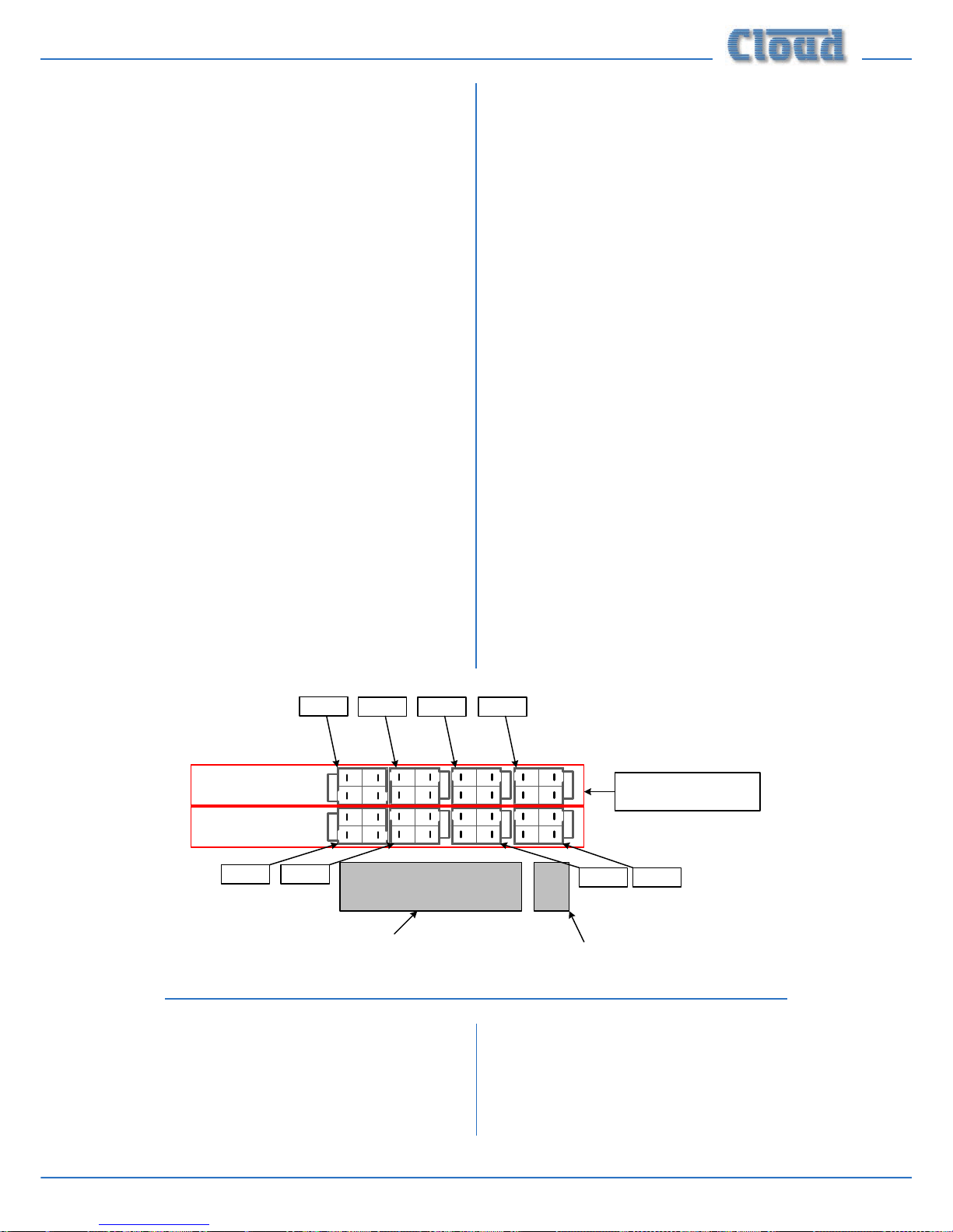
46-120 Installation and User Guide V1.1 29
5. Identify the rst transformer’s primary winding – this is
the red/black ying lead tted with a male connector. Plug
the female connector removed in Step 4 into this. Note
the pin and latch orientation – the connectors will only
mate one way.
6. If conguring the zone output for 100 V-line operation,
plug the transformer’s secondary winding – the other
ying lead (blue/mauve/white) - into the second ZONE
O/P socket; this will be the one paired with the socket
unplugged in Step 4, and closer to the SPEAKER
OUTPUTS connector. These are: CON43 (Zone
1), CON44 (Zone 2), CON45 (Zone 3) and CON46
(Zone 4). Note that CON43 is orientated at 180° relative
to the other three. See diagram below.
7. If conguring the zone output for 70 V-line operation,
plug the transformer’s other ying lead (blue/mauve/
white) into the ZONE O/P connector vacated in Step 4.
8. For each zone being converted to 100/70 V-line operation,
enable the channel’s 65 Hz hi-pass lter by moving
the appropriate jumper from OFF to ON: these are J3
(Zone 1), J4 (Zone 2), J8 (Zone 3) and J9 (Zone 4). See
page 30 for location of PCB jumpers.
9. Repeat Steps 3 to 8 for the other zones being converted.
10. Replace the cover.
Bypassing transformers in the 46-120T
and 46-120T
MEDIA
It may occasionally be necessary to revert one or more zone
outputs of a 46-120T or 46-120T
MEDIA to low-impedance
operation. In this case, follow the procedure below:
1. Disconnect the 46-120 from the mains.
2. Remove the top cover (10 screws) and orient the unit
with the rear panel towards you.
3. For the rst zone being converted to low impedance
operation, unplug the 4-pin female transformer secondary
connector from its ZONE O/P socket on the main
PCB immediately behind the rear panel SPEAKER
OUTPUTS connector. See diagram below.
4. Unplug the transformer’s 4-pin male primary winding
connector from the zone output ying lead. Check it is
for the correct zone - see table on page 28 for colour
coding.
5. Plug the zone output ying lead into the ZONE
O/P socket in the row further from the SPEAKER
OUTPUTS connector These are: CON38 (Zone
1), CON39 (Zone 2), CON40 (Zone 3) and CON41
(Zone 4). See diagram below.
6. For each zone being reverted to low impedance
operation, disable the channel’s 65 Hz hi-pass lter by
moving the appropriate jumper from ON to OFF: these
are J3 (Zone 1), J4 (Zone 2), J8 (Zone 3) and J9 (Zone 4).
See page 30 for location of PCB jumpers.
7. Repeat for the other zones being converted.
8. Replace the cover.
Z ONE1 O/ P Z ONE4 O/ PZ ONE 3 O/ PZ ONE 2 O/ P
SPEAK ER OUTPUTS
c o n n e c t o r
REMOTE POW ER DOW N
c o n n e c t o r
PLUG TRANSF ORMER
SECONDARY INH ERE F OR
100 V OPERATION
PLUG TRANSF ORMER
SECONDARY INH ERE F OR
70 V OPERATION
TH ESE CONNECTORS ARE
ALSO USED F OR LO-Z
OPERATION
CON38
CON46CON45
CON44CON43
CON41CON40CON39
Fitting the EQ security cover
A security cover is supplied with the 46-120 which can be
tted to the front panel to prevent access to the Zone EQ
preset controls. The MIC LEVEL, MUSIC LEVEL and
MUSIC SOURCE controls remain accessible and the CLIP
LED is still visible.
The panel is simply placed over the rotary control knobs
and secured in place with the four M3 x 6 hex-head screws
supplied.
Page 30
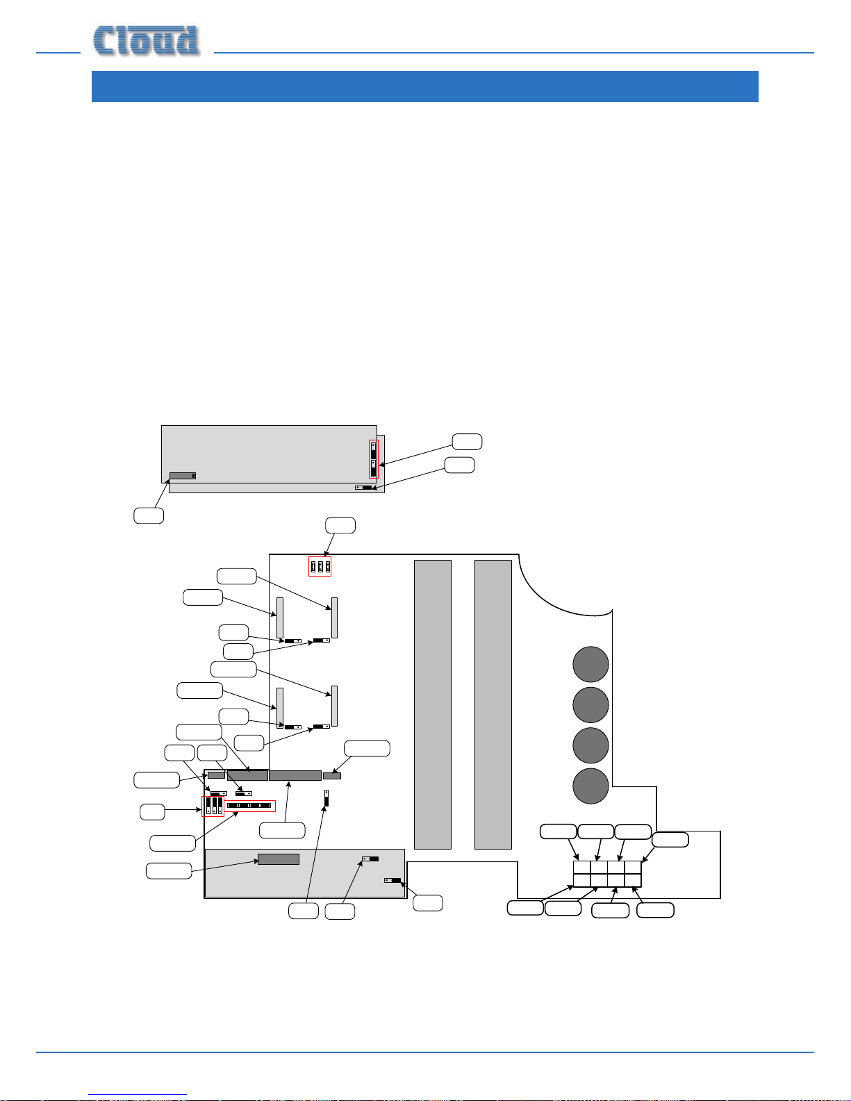
46-120 Installation and User Guide V1.130
APPENDIX
PCB jumper locations
The 46-50 has various internal jumpers, the setting of which may require alteration during installation. The diagram below shows
the locations of the internal jumpers (not to scale) on the internal PCBs, and the table below lists each jumper and its purpose,
together with the factory default setting.
Note that the 46-120 has three sub-boards in addition to the main PCB, which also carry one or more jumpers. The sub-boards
are i) the line input sub-board (immediately behind the rear panel line input connectors, ii) the mic control sub-board and iii) the
music control sub-board. Sub-boards ii) and iii) are mounted immediately behind the front panel rotary controls, and vertically
stacked with the music control sub-board uppermost.
Most jumpers have two possible positions; the black square in the symbol indicates the default setting. If any jumpers need to
be changed, turn the 46-120 off and disconnect it from the mains. Undo the 10 screws securing the top cover of the unit and
remove it. Use a pair of small pliers to gently remove the jumpers from the PCB headers and reposition them as required. Ret
the top cover using the original screws.
The main PCB diagram also shows the locations of the sockets for the optional loudspeaker EQ cards (CON2, CON3 &
CON4), the connectors relevant to the CDI-46 Digital Interface card and the Zone output connectors .
CON8
CON17
CON9
CON19
J1 J2
J3
J4
J8
J9
J5
(below sub-board)
LINE INPUT SUB-BOARD
MIC CONTROL SUB-BOARD
MUSIC CONTROL SUB-BOARD
J6
J7
J10-J13
J14
J15
J16
J17
J18
CON21
CON22
CON25
CON23
CON13
CON38
CON46
CON45
CON44
CON43
CON41
CON40
CON39
Page 31

46-120 Installation and User Guide V1.1 31
Table of internal jumpers and default settings
JUMPER LOCATION DESCRIPTION EFFECT DEFAULT
J1 Main board Mic 1 phantom power
OFF: MIC 1 phantom power OFF
ON: MIC 1 phantom power ON
OFF
J2 Main board Mic 2 phantom power
OFF: MIC 2 phantom power OFF
ON: MIC 2 phantom power ON
OFF
J3 Main board Zone 1 65 Hz High Pass Filter
OFF: full frequency response
ON: 65 Hz hi-pass lter enabled for Zone 1
OFF
1
J4 Main board Zone 2 65 Hz High Pass Filter
OFF: full frequency response
ON: 65 Hz hi-pass lter enabled for Zone 2
OFF
1
J5 Main board NO/NC Mute contacts
N/O: contact closure required for muting
N/C: contact opening required for muting
N/O
J6
Mic Control subboard
Mic over music priority
OFF: No priority – mics mix with music
ON: Music ducks when mics in use
ON
J7 Main board Mic over Facility input priority
OFF: No priority
ON: MIC 1 & 2 have VOX-triggered priority over
signals at facility port
OFF
J8 Main board Zone 3 65 Hz High Pass Filter
OFF: full frequency response
ON: 65 Hz hi-pass lter enabled for Zone 3
OFF
1
J9 Main board Zone 4 65 Hz High Pass Filter
OFF: full frequency response
ON: 65 Hz hi-pass lter enabled for Zone 4
OFF
1
J10 Main board Mic1, Zone 1 Access Bypass
PRESENT: Mic 1 has permanent access to Z1
ABSENT: Use access port to enable access to Z1
ON
J11 Main board Mic1, Zone 2 Access Bypass
PRESENT: Mic 1 has permanent access to Z1
ABSENT: Use access port to enable access to Z2
ON
J12 Main board Mic1, Zone 3 Access Bypass
PRESENT: Mic 1 has permanent access to Z1
ABSENT: Use access port to enable access to Z3
ON
J13 Main board Mic1, Zone 4 Access Bypass
PRESENT: Mic 1 has permanent access to Z1
ABSENT: Use access port to enable access to Z4
ON
J14A, B3
Music Control subboard
Zone 1 Line 6 priority
OFF: No priority
ON: Line 6 has VOX-triggered priority over other
sources in Zone 1
OFF
J15 Line input sub-board Zone 1 Line 6 priority release time
3S: 3 seconds. release time
6S: 6 seconds release time
ABSENT: 12 seconds release time
6S
J16
Music Control subboard
MOH/Utility source select
L1: MOH/Utility output always Line 1 input
L2: MOH/Utility output always Line 2 input
L3: MOH/Utility output always Line 3 input
L4: MOH/Utility output always Line 4 input
L5: MOH/Utility output always Line 5 input
L6: MOH/Utility output always Line 6 input
MP3: L1: MOH/Utility output always media player
2
Z1: MOH/Utility output follows Zone 1 selection
Z1
J17A, B, C
3
Main board MIC 1/TEL input transformer
OFF: MIC 1 input accepts standard mics
ON: MIC 1 input suitable for connection to
telephone system
OFF
J18A, B, C Main board Auto Power down time Binary weighting applies: see table at page 25.
OFF (APD
disabled)
1. On models 46-120T and 46-120T
MEDIA, default setting is ON.
2. Operative on Models 46-120
MEDIA and 46-120TMEDIA only.
3. All jumpers in the set must be moved together.
Page 32

46-120 Installation and User Guide V1.132
PSU capability and optional device
current consumption
In addition to supplying the Mixer Amplier’s circuitry, the
internal PSU has the capacity to power some additional items
which may form part of a complete system. These include
LM-2 active remote input modules (via the Facility Port),
loudspeaker EQ cards (tted internally), and possibly a PM
Series paging microphone (powered via an optional CDI-46
Digital Interface card).
The maximum current capacity of the PSU available for
powering additional items is 250 mA. Individual device
component limits are as follows:
• 150 mA for internal EQ cards
• 50 mA for LM-2s via the Facility Port
• 240 mA for PM Series paging mics via the CDPM/PM
port
Current consumption of the various items is listed in the
table below.
ITEM CURRENT PER UNIT
LM-2 mic/line input module 25 mA
PM4 paging microphone 72 mA
PM8 paging microphone 83 mA
Loudspeaker EQ cards (each) see note*
*Model-dependent. See separate datasheets at www.cloud.co.uk
The installer should ensure that the total current drawn by
all the additional items in a system does not exceed 250 mA
under any circumstances. If, for example 150 mA is needed by
EQ cards and 25 mA by an LM-2, only 75 mA is available for
a PM4 or PM8 paging microphone. If no EQ cards or tted
and there are no LM-2s in the system, then the full 250mA is
available
Note that PSU performance – and hence current
availability - will be degraded at ambient
temperatures in excess of 35°C.
EMC considerations
The Cloud 46-120 fully conforms to the relevant
electromagnetic compatibility (EMC) standards and
is technically well behaved; you should experience no
operational problems and under normal circumstances, no
special precautions need to be taken. If the unit is to be used
within close proximity to potential sources of HF disturbance
such as high power communications transmitters, radar
stations and the like, the performance of the mixing amplier
may be reduced; we suggest that the microphone cable screen
be connected to the shell of the XLR type connector and the
line input leads are kept as short as possible.
Ground loops
If, despite your best efforts, the completed sound system
‘hums’ you probably have a ‘ground loop’. The offending signal
source can often be identied by setting the volume control
to minimum, then disconnecting the input leads (both left &
right channels) on each line input until the ‘hum’ disappears.
This problem is often caused by terminating a screened input
cable into a signal source positioned a signicant distance
from the mixer. A good way of avoiding this potential problem
is to use signal sources (typically ‘consumer’ equipment) that
are double insulated with no connection to the mains supply
earth. If a signal feed were derived from a second mixer (a
club or microphone mixer for example) it would be perfectly
normal to expect this to be earthed; we suggest that a
transformer be used to isolate the signal and prevent a noisy
loop (see page 14).
Page 33

46-120 Installation and User Guide V1.1 33
Technical specications
Line Inputs
Frequency Response 20 Hz to 20 kHz: +0/-0.5 dB
THD + N 0.04% @ 1 kHz; 22 kHz bandwidth
Sensitivity 195 mV (-12 dBu) to 2.0 V (+8 dBu)
Input gain control range 20 dB
Input Impedance 47 kohms
Headroom 17 dB
Noise -90 dB rms; 22 kHz bandwidth
Equalisation HF: ±10 dB @10 kHz; LF: ±10dB @ 50 Hz
Microphone Inputs
Frequency Response 100 Hz -3 dB (xed lter) to 20 kHz ±1 dB
Distortion <0.03% @ 1 kHz, 80 kHz bandwidth
Gain Range 10 dB to 50 dB
Input Impedance 3.3 kohms (balanced)
Common mode rejection 70 dB typical
Headroom 17 dB
Noise -127 dB EIN, 20 Hz to 22 kHz (R
s
= 150 ohms)
Equalisation HF: ±10 dB @ 5 kHz; LF: ±10 dB @ 100 Hz
Outputs
Low Impedance Outputs
4 ohm load 120 W (170 W one channel driven) @ 1 kHz & 0.1% THD+N
8 ohm load 85 W (100 W one channel driven) @ 1 kHz & 0.1% THD+N
Frequency response -1 dB @ 20 kHz, -0.5 dB @ 20 kHz
Distortion <0.04% @ 1 kHz, 80 kHz bandwidth
100/70 V-line output*
Min. load
70 V balanced – 42 ohm min. load
100V balanced – 83 ohm min. load
Frequency response -3 dB @ 65 Hz (lter), -2.5 dB @ 20 kHz
Distortion <0.06% @ 1 kHz, 80 kHz bandwidth
*with optional CXL-46T transformer(s)
Page 34

46-120 Installation and User Guide V1.134
General specications
Amplier protection Dynamic Clip Protection, VI Limiting, DC Offset, thermal & switch-on delay
Cooling Variable speed DC fan (stationary in Idle Mode)
Power input 230 V ±5% (115 V ±5% by internal connection)
Fuse rating 230 V: T4A; 100/115 V: T8A
Fuse type 20 mm x 5 mm HBC
Power consumption (For
thermal dissipation subtract
power in the load)
External remote power-down 4.7 W 7.75 VA
Idle – 4 chs. APD 13.4 W 16.75 VA
Idle – 3 chs APD 16.3 W 20.5 VA
Idle – 2 chs APD 19.2 W 24.9 VA
Idle – 1 ch APD 22.2 W 29.4 VA
Idle, all chs active 25.2 W 33.6 VA
Noise input, 1/3 rated power, 4 ohms 440 W 560 VA
Noise input, 1/3 rated power, 8 ohms 275 W 362 VA
Noise input, 1/8 rated power, 4 ohms 280 W 370 VA
Noise input, 1/8 rated power, 8 ohms 175 W 240 VA
Dimensions
Net
482.6 mm x 88 mm (2U) x 406.9 mm
19 in x 3.46 in (2U) x 16.02 in
Shipping
59.8 cm x 15.7 cm x 54.2 cm
23.5 in x 6.2 in x 21.3 in
Weight
Net
46-120/46-120
MEDIA: 11.75 kg (26.32 lbs)
46-120T/46-120TMEDIA: 15.75 kg (35.28 lbs)
Shipping
46-120/46-120
MEDIA: 13.95 kg (31.25 lbs)
46-120T/46-120TMEDIA: 17.95 kg (40.21 lbs)
Page 35

46-120 Installation and User Guide V1.1 35
Page 36

Cloud Electronics Limited
140 Staniforth Road
Shefeld S9 3HF
England
Tel: +44 (0)114 244 7051
Fax: +44 (0)114 242 5462
email: info@cloud.co.uk
web: www.cloud.co.uk
Cloud Electronics USA
1200 Iron Horse Drive, Unit A
Park City
Utah 84060.
United States of America.
Toll Free: 0855 810 0161
email: sales@cloudusa.pro
web: www.cloudusa.pro
 Loading...