

Cloos GLC 353 MC3, GLC 503 MC3, GLC 553 MC3 Operating Instructions Manual

16
GLC 353/503/553 MC3Operating instructions
GLC 353 MC3
GLC 503 MC3
GLC 553 MC3
MIG/MAG Welding Machine OPERATING INSTRUCTIONS
and SPARE PARTS LISTS
PLEASE KEEP SAFELY FOR FUTURE REFERENCE
128/01.01
CARL CLOOS
Schweißtechnik GmbH
Industriestr. • 35708 Haiger
Tel. +49 2773/85-0
Fax. +49 2773/85-275
http://www.cloos.de
info@cloos.de


1
GLC 353/503/553 MC3Operating instructions
Operating Instructions
MIG/MAG Welding Machine
GLC 353 MC3
GLC 503 MC3
and
GLC 553 MC3
with
CK 98 A Wire Drive Unit
Print No.: 128
Issued: 01/01
Subject to technical alterations

2
GLC 353/503/553 MC3Operating instructions
W A R N I N G !
Prior to the first commissioning, all persons who are involved with
this machine should read this operating instruction manual
carefully and confirm that they have done so in writing.
Please keep the operating instruction manual easily accessible for
all welders and service staff!
The best place is the welding machine itself!

3
GLC 353/503/553 MC3
Operating instructions
EN50199:1995
Appendix A (information)
Installation and use
The user is responsible for the installation and operation of the welding machine according to the manufacturer's
instructions. If there is electromagnetic interference, the user is responible for finding a solution with the aid of
the manufacturer of the welding machine, e.g. grounding of the weld current circuit, electromagnetic screening
and/or inlet filter.
A.1 Evaluation of the area
Before installing the welding machine, the user has to evaluate any possible electromagnetic problems in the
surrounding area. The following must be taken into consideration:
a) Other mains supply lines, control lines, signal and telecommunication lines above, below and next
to the welding machine.
b) Radio and TV broadcasting station and receiver.
c) Computer and other control units.
d) Safety devices, e.g. protection for commercial equipment.
e) Health of persons in vicinity, e.g. if using pacemakers and hearing aids.
f) Units for calibration or measement.
g) Resistance to interference of other equipment in the surrounding area. The user must ensure that
other equipment used in the vicinity is electromagnetically compatible. This may require additional
safety measures.
h) The time of day when welding or other activities are being carried out.
The extent of the surrounding area to be considered depends on the construction of the building and other
activities which take place there and may exceed the boundaries of the property.
A.2 Procedure to reduce emissions
A.2.1 Mains supply
The manufacturer recommends that the welding equipment is connected to the mains supply. Where there is
some interference, additional safety precautions may be necessary, i.e. filter for the power supply.
A.2.2 Maintenance of the welding equipment
Regular maintenance intervals are recommended by the manufacturer.
A.2.3 Weld cables
Welding cables should be as short as possible and should be run close together on or near to the floor.
A.2.4 Potential equalization
The electric connection of all metal parts in and near a welding machine should be taken into account. The metal
parts connected to the workpiece may increase the risk of an electric shock if the welder touches these metal
parts and the electrode at the same time. The welder should be protected against all connected metal parts.
A.2.5 Earth connection of workpiece
It must be ensured that earthing of the workpiece does not increase the risk of accident to the user or causes
damage to other electrical equipment.
A.2.6 Screening
Selective screening of other cables and equipment in the vicinity may reduce electrical interference. Screening
of the complete welding equipment may be considered in special situations.
5/96

4
GLC 353/503/553 MC3Operating instructions

5
GLC 353/503/553 MC3
Operating instructions
Safety specifications..........................................................................................7-9
Particular information for welding ..............................................................................7
Technical data .............................................................................................9
General product description ................................................................................ 10
Operating instructions ................................................................................... 10-13
Transport ...........................................................................................10
Mounting area, floor requirement, environment ..................................................... 10
Storage ...........................................................................................11
Assembly ...........................................................................................11
Power supply ...........................................................................................11
Torch connection, earth cable ...............................................................................11
Shielding gas, reducing valve................................................................................11
Wire drive ...........................................................................................12
Coolant ........................................................................................... 12
Commissioning ...........................................................................................13
Special safety devices......................................................................................... 13
Temperature protection ......................................................................................... 13
Overload protection ...........................................................................................13
Operation / Service ...........................................................................................13
General instructions for shielded gas welding ............................................13-14
Instructions for welding...................................................................................... 15
Operation......................................................................................B-1-44
Mechanical description ............................................................................... L- 1-24
Illustrations welding machine GLC MC 3..............................................................2-5
Spare parts list GLC MC 3....................................................................................6-7
Illustrations wire drive unit CK 98 A......................................................................8-9
Spare parts list CK 98 A........................................................................................10
Sectional drawing: 2 + 2 roller system with central connection..............................11
Spare parts list 2+2 roller drive compl. with central connection
for steel and flux cored wire.............................................................................. 12-13
Sectional drawing: 2 + 2 roller system with central connection.............................. 14
Spare parts list aluminium equipment for 2+2 roller drive with central connection ..... 15
HD Drive ..........................................................................................................16
Spare parts list HD Drive ..................................................................................17-18
Sectional drawing cable assembly for CK 98 A ..................................................... 19
Spare parts list cable assembly CK 98 A............................................................... 20
Sectional drawing cable assembly for CK 98 A, cable assembly connectable ...... 21
Spare parts list cable assembly CK 98 A, cable assembly connectable................22
Sectional drawing wire coil holder compl...............................................................23
Spare parts list for wire coil holder compl. ............................................................. 24
Electrical description ................................................................................ L- 25-53
Circuit diagrams GLC 353 MC 3.......................................................................25-27
Electrical parts list GLC 353 MC 3.................................................................... 28-33
Circuit diagrams GLC 553 MC 3.......................................................................34-36
Electrical parts list GLC 553 MC 3.................................................................... 37-40
Circuit diagram CK 98 A ........................................................................................ 41
Electrical parts list CK 98 A .............................................................................. 42-43
Circuit diagram CK 98 A with installation kit remote controller socket ..............44-45
Electrical parts list CK 98 A .............................................................................46-47
Circuit diagram CK 98 A, cable assembly connectable ................................... 48-49
Electrical parts list CK 98 A, cable assembly connectable ..............................50-51
Circuit diagram remote controller .......................................................................... 52
Electrical parts list remote controller...................................................................... 53
APPENDIX
Supplement cooling water device .......................................................................... 51
List of addresses - CLOOS representatives in Germany/abroad ..................... A1-A4
INDEX

6
GLC 353/503/553 MC3Operating instructions

7
GLC 353/503/553 MC3Operating instructions
Safety specifications
General information
Warning!
This is a class A equipment which may cause radio
interferences in residential areas. In such a case the
operator may be asked to take adequate steps on his
account.
The GLC 353/503/553 MC3 machine with CK 98 A is
built according to EN 60 974-1. It corresponds to the
latest "state of the art" engineering and its reliability
is proven. It must be operated by trained personnel in
accordance with the following instructions to provide
safe and efficient operation.
The machine is not suitable for thawing
pipelines due to Fire risk !
Flammable gases or gases which induce a chemical
reaction, such as Acetylene, Propane, pure Hydrogen, pure Oxygen are prohibited.
Please note the following!
- Safety regulations VBG 15
- Safety regulations VBG 4
- Fire protection rules
- Welding and maintenance to be carried out by
qualified personnel only.
- The machine must be switched-off and
disconnected for all maintenance work.
- Repair of electronics to be carried out by service
personnel only. If repair work is carried out by
unauthorized persons and safety regulations are
not adhered to, the warranty becomes invalid.
This welding machine is intended for industrial use
and must not be used in residential buildings.
As >16 Amp are required per phase, this machine is
subject to the IEC 61000-3-4 standard or EN 61000-312, when it is available. In order to avoid
electromagnetic interference (EMI), certain conditions
must exist (size of mains impedance) for connection
to the public low voltage network. Please inform the
relevant electricity supplier about this machine’s
connection. Please do not hesitate to contact your
Electricity supplier or the manufacturer if you need
help or information.
Particular information for welding
Personal protection (rays, gases, vapours)
— When welding, dry protective clothing, apron,
helmet and gloves as well as solid work shoes
should be worn.
— Use a protective shield or helmet with glass, with
DIN marking, outside clear, inside tinted.
— Protect other persons in the vicinity of the
welding area from UV rays and spatter by
suitable, non-flammable partition walls.
— Always wear safety glasses if you are in an area
where welding takes place.
— Wear safety glasses with side protection when
you are welding or when removing slag.
— Caution! UV rays are released during welding.
Protect body and particularly the eyes. Keep
protective ointment and eye drops available.
— All metal vapours are toxic! Be careful with
alloys which contain lead, cadmium, copper,
zinc, nickle, chrome, berillium.
— Parts, cleaned with chlorinated agents, cause the
toxic gas phosgen to form in the arc.
Caution Risk of poisoning in narrow places !
If shielding gas hoses are not tight or the
shielding gas valve gets caught unintentionally,
shielding gas may escape to such an extent that
the oxygen content of the inhaled air decreases;
symptoms of poisoning appear which may lead to
unconsciousness and suffocation. Sufficient fresh
air must be provided! Please check the gas
supplying parts at regular
intervals.
Fire prevention (explosion)
— Remove all flammable materials around the
welding place or cover these with a nonflammable material.
— Hot slag or spatter might cause fires if in contact
with flammable materials.
— Only use shielding gases suitable for welding,
such as Argon, CO2 and Argon and CO2 or
Argon, CO2 and O2 mixtures.
Never use flammable gases like Acetylene,
Propane, Hydrogen or fire supporting gases such
as Oxygen.
— Never weld on drums, tanks or similar containers
unless they have been thoroughly cleaned and
you are sure that no toxic, flammable or explosive vapour can develop.
— Fire fighting agents such as water or sand or a
fire extinguisher should always be available.
— Confined spaces must have a free passage
allowing escape in case of danger.
— Please observe the weld area and its
surroundings when welding has finished. Fire
may break out later due to smoldering.
Electrical danger (current, voltage)
Pacemakers
Wearers of pacemakers may potentially by at risk
from arc welding. When MIG/MAG welding the risk is
from magnetic fields and when TIG welding from high
voltage pulses of the arc ignition units.

8
GLC 353/503/553 MC3Operating instructions
As there are several versions of pacemakers, the
situation must be clarified with the relevant
pacemaker manufacturers or their representatives
(hospital etc.).
— Switch off the welding machine when not in use
to prevent any electrical risk.
Warning! The terminal voltage of the welding
machine may be up to 113V= or 48V~!
— If you have to stand on metal or in a wet area
during welding, insulation with suitable dry
materials is required.
— Avoid contact with wet or conductive metal parts;
wear dry clothing.
— Always maintain correct insulation of cables,
plugs and welding torches. Do not overload
these parts.
— Keep everything dry, including clothing, welding
area, cables and welding machine. Repair
immediately any faulty water cooling lines.
— Welding machines may only be used if all covers
are present and correctly installed.
— Although the machine is marked “S” (approved
for welding in environments with increased
electrical hazard), the power source itself may
not be installed here, because of the mains
voltage of 400 V; only the welding torch and the
wire drive unit are permitted at such places.
— Before any work is carried out inside the power
source, the mains switch must be switched-off
and the mains plug disconnected.
After disconnecting the mains plug, wait at least
2 minutes until the capacitors have reached safe
values.
— Be careful when changing the wire coils. Switch
off the machine so that the switching command
cannot be initiated.
— Lock the wire coil holder, by turning the locking
button to prevent the wire coil becoming loose.

9
GLC 353/503/553 MC3
Operating instructions
Technical data:
GLC 353 MC3 GLC 503 MC3 GLC 553 MC3
Input:
Nominal input voltage 3x400V ac 3x400V ac 3x400V ac
Nominal frequency 50Hz 50Hz 50Hz
(Other voltage and 60 Hz frequency are available upon request)
Input - peak current 23A 37A 47A
Input - continuous current 19A 27A 40A
Slow blow fuse 25A 35A 50A
Power supply cable 4x4mm
2
4x6mm
2
4x10mm
2
Input constant power 13.1kVA 18,7kVA 27,7kVA
Power factor cos Phi 0.92 0,96 0,96
Output:
Max. open circuit voltage 56V 70V 70V
Welding range for MIG/MAG 40A/15V-350A/40V 40A/12V-500A/42V 40A/12V-550A/
44,5V
Duty cycle 100% 300A/29V 400A/34V 500A/39V
Duty cycle 60% (10min.) 350A/31.5V 500A/39V 550A/41,5V
Type of protection IP 23 IP 23 IP 23
Type of cooling F F F
Insulation class F (1550C) F (1550C) F(155°C)
Dimensions LxWxH power source 960x460x930mm 1190x530x930mm 1190x530x930mm
Weight of power source 153kg 220kg 220kg
Dimensions LxWxH wire drive unit 610x380x355mm
Weight wire drive unit 22kg
Torch water cooling 2.0 l/min. at 3.0 bar (30m Ws)
Continuous noise level 1 m a height of 1.6 m and a distance of 1 m from the machine:
Machine noise when switched on 58 dB (A) 60 dB (A) 68 dB (A)
Arc noise at max. output 80 dB (A) 82 dB (A) 85 dB (A)
according to DIN 45 635, part 1
Wire feed infinitely adjustable 0 ... 24m/min. 0 ... 30m/min. 0 ... 30m/min.
Permission EN 60 974-1
The machine is designed for manual MIG/MAG welding of all metals.
Manual DC-current TIG welding with lift-arc ignition is possible.
All coated stick electrodes can be welded.
- The machine corresponds to the machine rules (98/37/EG), the low voltage rules
(73/23/EWG) and the rules for electromagnetic compatibility(89/336/EWG).
- The machine is approved for welding in environments with increased electrical hazard and is marked with
the letter „S“.

10
GLC 353/503/553 MC3Operating instructions
Shielding gases
The following gases are used for MIG/MAG welding:
Pure Argon, CO2, mixtures of Argon and CO2 or
Argon, CO2 and O2.
Flammable gases or gases which induce a chemical
reaction such as Acetylene, Propane, pure Hydrogen, pure Oxygen are prohibited.
Operating instructions
Transport
The machine must always be transported without
gas cylinder.
All cables must be wound up and put on the machine
before transport.
The machine can be moved on its wheels. When
using a fork lift truck, the forks must be applied
between the wheels. The machine must lie
crosswise on the truck.
Transport by means of a crane is also possible. If
jack rings are available all of them must be used
because of the carrying capacity and load
distribution. If there are no jack rings, two belts must
be used, pulled crosswise under the machine inside
the wheels.
Mounting area, floor requirement,
environment
- The machine should be installed on a horizontal,
flat surface, dust-free and well ventilated.
- The distance between other machines or
buildings should at least be 0.50 m (24 inches on
all sides, to aid ease of servicing.
- The cooling air entrance and exit grills must not
be restricted in any way
- The ambient temperature may vary from -100C
to +400C .
- The machine is protected to IP 23 which does
not permit use in the rain. If necessary, it should
be covered. In this case ensure that the cooling
air flow is not affected!
- The machine is marked "S", which means
approved for welding in environments with
increased electrical hazard; however, the power
source itself must not be installed there due to
the mains voltage of 400 V; only the welding
torch is permitted in such places.
General product description
Application possibilities and
restrictions
The transistorized MIG/MAG pulsed arc welding
machine type GLC 353/503 MC3 with wire drive unit
type CK 98 A is a welding machine with micro computer
control and a new air cooled power part with extremely
quick regulation due to particularl switch controller
technology. Outstanding welding features and low power
losses result from this. Aimed drop deposition with a
highest possible spatter reduction when welding with
Argon and Argon rich mixed gases with max. 20% CO
2
part. It can be welded pulse free with all arc kinds under
Argon, Argon O2 mixed gases with multicomponent
mixed gases and under pure CO2.
Remarkable features of the wire drive units are the
precise rotation control (tacho control) and high motor
power (100 W) with four quadrant regulation (D).
2 + 2 roller system and 4 roller system guarantee safe,
slip-free and low abrasion wire transport. The adjustment
of the counter pressure is reproducible and comfortable
in handling.
The arc burns between wire and workpiece under
shielding gases (MAG = Metal active gas and MIG =
Metal inert gas procedure).
The wire electrode continuously unwound off the reel
until a reel is used up. The coil weight is 15 kgs with
steel and 4 ... 5 kgs with Aluminium.
The wire thickness and welding torches to be used
depend on material thickness and seam shape.
Power sources and wire feed are in separate housings
connected by a cable assembly. The complete system
is mounted on four rubber tyred wheels.
The machine is connected to a three phase current
supply. Direct current is available at the outlet.
The machine is set up for manual, mechanical and
robot MIG/MAG welding all metals. Manual d.c. TIG
welding with lift-arc ignition is possible.
The machine is suitable for welding all kind of flux cored
wire electrodes.
The machine is not suitable for thawing pipelines.
- Fire risk! -

11
GLC 353/503/553 MC3
Operating instructions
Storage
- The machine should be stored indoors at a
temperature between -100C and +400C and
should be covered.
- If the coolant is not emptied, please ensure that
an anti-freeze agent is added. The coolant must
be disposed of and must not enter the main
drainage system.
Assembly
A complete machine comprises:
1. Transistorized MIG/MAG pulsed arc
welding machine type
GLC 353/503MC3
2. Wire drive unit type Typ CK 98 A
3. Cable assembly, connectable
4. MIG/MAG welding torch
5. Standard accessories including:
Earth cable
Reducing valve with l/min.-scale
Tools
Set of fuses for power source
6. Options, if required
The individual components, MIG/MAG welding
machine, connectable cable assembly, wire drive
unit, gas cylinder and reducing valve have to be
assembled. The water hoses must not be
exchanged. The flow is marked blue!
Make sure cooling liquid is sufficiently filled.
All water-cooled machines are supplied with a 5 litre
container of ready-to-use mixture.
Power supply
The power supply must be installed by qualified
personnel only!
Please ensure that the mains voltage to be used is
identical to the operating voltage indicated on the
machine type plate.
According to the connection regulations the machine
has to be connected by means of a mains cable. The
power supply must be fused according to the
connection regulations. To ensure good welding
performance the cross section of the connection
cable must be adequate.
The phases L1, L2, L3 and PE are connected. The
neutral wire (N) remains free.
A correct conductor connection must be provided!
(VDE regulations).
Torch connection, earth cable
- The welding torch is connected to the central
connection, item 13, the water hoses to the
connections items 119 and 120 - they must not
be exchanged (insufficient cooling of the welding
torch). The flow is marked blue. The control line is
connected to the socket, item 109.
- The earth cable is connected to the current
connection, item 79, and locked by turning right.
- The gas cylinder is placed on the base plate, item
87, at the rear of the machine and is secured by a
chain, item 87/2, which is connected to the
holder, item 87/1.
Shielding gas, reducing valve
— The reducing valve is screwed onto the gas
cylinder and connected to the machine by means
of the gas hose, item 215. The gas quantity is
adjusted at the reducing valve. For this purpose
the machine must be switched on and the torch
button or key “gas manual”, item 103 must be
actuated at the wire drive unit.
— The normal gas quantity for Argon and mixed
gases is 8 - 15 l/min. and for CO2 10 - 20 l/min.
— In general, carbon dioxide with a percentage
purity of 99.9 % is used for welding with
unalloyed or low alloy steels with a strength of 37
- 60 kgs. In Germany the gas cylinders have the
additional marking “S” (= Schweißzwecke welding purposes).
These steels can be welded with the gas mixture
(AR + CO2 + O2), high alloy steels, e.g. chrome
nickel steel require protective gas K2 ( Ar + 2%
CO2). Aluminium and other nonferrous metals
require pure Argon 99.9 %.
— The flow quantities indicated on the extraction
manometer depend upon choke setting, item
113/2 in front of the gas valve, item 111. This
choke has a nominal diameter of 0.6 mm. The
nominal diameter size 0.6 is clearly marked on
the litre scale of the extraction manometer. For
example, in the case of 4 bar, the flow quantity is
11.5 l/min.
— In the case of ring mains which operate at less
pressure, it is not possible to set a flow quantity

12
GLC 353/503/553 MC3Operating instructions
of 11.5 l/min. In this case the choke diameter has
to be enlarged from 0.6 to 2.0 mm or the gas
retaining unit, item 113 exchanged for item 113 a,
so that a greater flow is created at a lower
pressure.
— If the original flow meter is not connected, the
flow quantity at the gas nozzle of the welding
torch must always be checked with a suitable
flow meter.
— A simple gas flow measuring tube is available
under ref. No. 097 03 04 00.
Wire drive
Wire drive rollers, item 18, wire guide unit, item 10 and
wire inlet nozzle, item 15 are marked according to the
wire size, to prevent wrong nozzle size being used by
mistake. This also applies to the contact tips and liners
of the welding torch, which are also marked with the
wire sizes.
When changing the wire drive rolls and gear wheels,
force must not be used to mount them on the gear
shafts, e.g. hammer or similar because this might
cause damage.
Prior to installation, all parts must be cleaned and except the drive rolls - be greased.
The welding wire itself is threaded inside the wire drive
unit throughout the wire guide spiral, item 12, the wire
drive rollers, item 18, the wire guide piece, item 10, and
the wire inlet nozzle, item 15. The wire is transported to
the torch by actuating the torch button wire manual,
item 104 on the wire drive unit. To do this the machine
must be switched on. The pressure arms, item 7 and
item 8 must only be sufficiently pressed against the
pressure units as is necessary for the relevant wire type
and size. The adjustment is reproducible. The pressure
arms swing out for threading the wire or exchanging the
wire drive rollers. The two pressure units, item 9, have
to be adjusted equally.
The pressure units of the pressure roller brackets
must not be set at more than -3-
The brake of the wire coil holder can be adjusted with
the tightening screw, item 8. The wire coil should not
move when the motor brakes, to prevent wire windings
falling off the coil and kinking or short circuits occurring.
If the brake no longer works, the brake disk, item 7 must
be replaced!
The wire coil must be secured on the wire coil holder
with the locking button, item 2, to prevent it falling off.
Coolant
As soon as the welding torch is connected, the coolant
can be filled into the cooling system. It is absolutely
essential that distilled water is used! Do not use
chlorinated water or water with a high mineral content
because of its electrical conductivity. The cooling system
cannot be completely emptied. Therefore, to avoid
damage from frost, an anti-freeze agent must always
be added, which also protects against corrosion. Only
use Glykorol EL. CLOOS ref. No. 000 01 01 22!
A five litre container of a ready-to-use mixture of: two
parts distilled water and one part Glykorol EL
(up to - 20° C) is supplied with each water-cooled
machine. CLOOS ref No. 000 01 01 31.
The water container is filled via filling connection,
item 86. A certain vacuum must remain so that the
cooling liquid can return during water blow through
without overflowing. The drain cock, item 93, at the
rear of the machine must then be opened until the
coolant flows out. The water pipes are thereby
vented and coolant is brought to the pump.
WARNING! Avoid dry-running of the pump, even
for a short period! Otherwise the shaft seal may
be damaged.
With regard to the construction of the pump it is
important that the cooling liquid is absolutely clean.
Impurities such as sand or swart as well as sticky
residues, lubricating grease etc. may damage the
pump.
Be careful after torch repairs !
Danger! Glykorol EL
is dangerous if swallowed and
harmful to skin! Carefully wash
your hands after filling!!
Safety precaution!
Keep out of reach of children.
The water hoses are filled when the machine runs.
When using very long cable assemblies, the resulting
loss of water in the cooling water container must be
replenished. Please note the max. coolant quantity!

13
GLC 353/503/553 MC3
Operating instructions
Special safety devices
Temperature protection
The main transformer, main rectifier and
transistor cascade are protected from
overheating by thermal switches which cut off
the welding command. This is indicated by a
yellow control lamp and as plain text on the
display. The machine should remain switched
on so that cooling air can continue cooling.
Overload protection
The cooling fan and water cooling pump are
protected from overheating by thermal
switches. Overheating can be caused by
overcharging the motor windings. The thermal
switches cut off the welding command and the
tension from the motor winding. This is
indicated by a yellow control lamp and as plain
text on the display.
Switch the machine off and eliminate the
cause for overheating.
Service
The machine can be commissioned when the
welding machine, cable assembly, wire drive unit,
welding torch, earth cable, shielding gas cylinder with
reducing valve and welding wire have correctly been
connected and installed.
- It should be ensured that the flow and return
water hoses of the wire drive unit and the torch
are not mixed up (insufficient torch cooling). The
flow is marked blue.
- The cable assembly must be protected from
tension on the power source with the enclosed
hose clip on the upper part of the cylinder holder.
- The cable assembly must be protected from
tension of the wire drive unit at the baseplate with
the second hose clip.
The tank cap must always be screwed down to
prevent contamination of the cooling liquid!
The welding machine must always be switched off
when the torch cooling circuit is interrupted, for
example when the welding torch is removed. 'The
water connections then shut automatically to prevent
the coolant running out. The pump produces a
dynamic pressure of 3,8 bar. If this pressure exists
for a long period, the pump and the coolant heat up
to such an extent that damage and leakages may
occur.
WARNING!
The machine is provided with a water filter in front of
the suction side of the cooling water pump.
When the message "lack of water" occurs, this filter
must be checked for impurities, be removed, washed
and reinstalled.
Do not change the mounting direction! Arrow head
away from pump ! Do not install a water filter without
a flow control switch.
Water cooling device
When welding at high ambient temperature (greater
than 40°C) with high capacity (greater than 500 A)
it is recommended that the cooling water for the
torch is cooled by a separate water cooling device,
i.e. ST 157/2. This device prevents the ambient air
being warmed up by the components which are
being cooled, as is the case with an integrated
water cooling system.
Commissioning
The machine is switched on with the mains switch,
item 42.
Pum and fan are switched on after approx. 10 s for 1
minute. The cooling air is suctioned at the front side
and blown out at the rear side (gas cylinder).
Interval switch off for pump and fan!
Pump and fan are only switched on when welding.
After welding they run for approx. 5 more min. in
order to recool accordingly. This avoids that in the
case of longer downtimes dirty cooling air is sucked
into the machine. Furthermore, noises and current
consumption are reduced.
The GLC 553 MC3 fan is provided with two power
steps. Normally, the low step I is switched on. If
cooling is not sufficient, the stronger step II can be
used.

14
GLC 353/503/553 MC3Operating instructions
General instructions for shielded gas
welding
With MIG/MAG shielded arc welding machines both
short arc and spray arc can be used.
Short arc is also called “dip-transfer arc”. When using
the short arc procedure, there is a relatively low welding
density on the welding wire so that the additional
material passes on to the workpiece in the shape of
individual drops (approx. 50 - 80 drops per second).
The heat input itself is relatively low so that with this
method thin sheet as well as root and vertical up seams
with thicker plate can be welded (also awkward position
welding).
With the spray arc technique a high current density is
used on the wire cross section. The welding material no
longer passes in drops onto the workpiece but as a
spray. Wherever an adequate welding performance as
regards the fusion quantity is required, the spray arc
process is the only one to consider.
At less than approx. 180 Amps/mm2 current density
with steel wire short arc welding is generally considered,
whereas with more than 200 Amps/mm2 the spray arc
technique starts to be used. The transition from short
arc to spray arc varies according to the different kind of
gases.
Using CO2 as shielding gas, deep penetration is a
feature with steel welding, whereas, Argon S 5 (Ar +
5 % O2) for example gives only slight penetration. Using
gas mixtures (normal ratio about 90 % Ar + 5 % CO2 +
5 % O2) penetration lies somewhere between the two
above gases.
Due to the deep penetration when using CO2, the
wedge angle must not exceed 30 - 40°. Less welding
material is therefore required on the one hand and on
the other, the welding efficiency is increased.
In the case of thin sheet, up to 3 mm maximum, the
vertical down seam position is advisible, as this results
in a higher welding speed and the surface appearance
of the seams is also improved.
High alloy steels are welded using protective gas K2 (Ar
+ 3% CO2).
Non-ferrous metals such as aluminium, copper, bronze,
etc. are welded with pure Argon 99.9% or gas mixtures
consisting of Argon and Helium (65 % Ar + 35 % He).
In the case of copper welding it is also necessary to
preheat the workpiece from 4 - 5 mm thickness upwards
to coat the welding edges with a deoxidizing paste.
During welding the welding torch must be held at an
angle of 5° towards the vertical of the workpiece. The
tip is approx. 15 mm away from the workpiece wire
diameter.
Special instructions for pulsed arc
welding
Spray arc
Using Argon or Argon mixtures with less than 20% CO
2
and sufficient high power and voltages the material
transition is carried out freely in the form of small drops
or drop chains without short circuit formation. Therefore
a spatter free welding is possible with the spray arc. A
precondition is, however, the use of the above shielding
gases. Due to the high energy input and the high
deposit efficiency this technique is only used - similar to
the semishort circuiting arc weldment - for the filler and
cover pass welding in the w- and h-position.
Pulsed arc
The short-circuit free material transition of the spray arc
is made use of by the pulsed arc technique. The energy
source switches periodically to a higher pulse current,
which makes an aimed and well controllable material
transition possible, while the base current serves for
the ionization of the arc distance and the preheating of
the wire electrodes end and the material surface. By
means of these current pulses a free material transition
in the rhythm of the pulse frequency is achieved.
This technique allows a good mastery of the molten
pool, which is very important for out-of position welding.
Due to the high pulse currents in the case of small base
currents relatively thick electrodes can be used.
The working range in the pulse technique is restricted
to the min. or max. current capacity of the wire electrode
used.
The disadvantage of the complicated adjustment of the
welding process (max. 5 parameters) is compensated
in case of an aimed variation of the welding parameters.
Therefore the degree of dilution in case of deposit
welding is for example kept small, or when selecting a
material transition with one drop per pulse with
corresponding drop size a virtually spatter-free welding
is achieved.
The correct pulse current adjustment is achieved when
the wire end can be seen as tip in the arc.

15
GLC 353/503/553 MC3
Operating instructions
Instructions for welding
Non-coppered welding wires, aluminium and special
steel wires tend extremely to stick to the current tip in
the welding torch. Especially in the case of thin wires,
it often becomes necessary to take peak current
limitation measures for the ignition from the power
source, measures which can be supplied optionally.
The software in the GLC ....MC3 machines automatically
sets this peak current limitation, if required.
In the case of special steel wires a plastic core must be
installed in the welding torch, as this is basically required
for aluminium. In metal spirals are being produced
scorching points which considerably affect the wire
feed.
When MSG (metal shielded gas) welding the welding
wire is charged with the potential positive welding
current whereas the power source minus pole is often
connected to the mains protective conductor via earth
connection.
For this reason it is important that the welding wire in the
wire drive unit, the wire drum and the wire dereeler or
in its transport section does not touch the mains earth
conductor or the counter potential negative welding
current (welding compound).
This kind of short circuit causes the weld result to
deteriorate and may destroy components. There is a
risk of fire due to the hot welding wire sections.


Index B-1
GLC 353/503 MC3
Operating Instructions
GLC 353/503 MC3
Index
E Introduction.................................................................................................. 3
B Operation................................................................................................. 3-10
B1 Operating and display elements ................................................................. 3
B1.1 Operating and display elements on the power source .......................... 4-7
B1.2 Operating elements on the wire drive unit ................................................. 8
B1.3 Working modes............................................................................................ 9
B2 Welding ................................................................................................. 11-22
B2.1 Procedure: MIG-MAG Normal 2 knob operation ................................. 12-13
B2.2 Procedure: MIG-MAG Normal Synergic .............................................. 14-15
B2.3 Procedure: MIG-MAG Pulse Synergic ................................................. 16-17
B2.4 Procedure: TIG Direct Current ............................................................. 18-19
B2.5 Procedure: Coated stick electrodes ................................................... 20-21
P Programming ........................................................................................ 23-34
P1 Operating elements for programming ...................................................... 23
P2 Program steps ........................................................................................... 24
P3 Operating modes when programming ................................................ 24-25
P4 Programming a weld procedure sequence ........................................ 26-31
P5 Calling up a weld procedure sequence ................................................... 32
P6 Correct a weld procedure sequence ........................................................ 32
K Configuration menu (Extension from software V1.56 up) ................. 32-34

IndexB-2
GLC 353/503 MC3
S Faults ..................................................................................................... 35-37
S1 Problems during operation .................................................................. 35-36
S2 System fault Overtemperature .................................................................. 37
W Maintenance .......................................................................................... 38-40
W1 Information, Intervals ............................................................................ 38-39
W2 Special instructions .............................................................................. 39-40
O Options .................................................................................................. 41-44
O1 Key-operated switch ................................................................................. 41
O2 Serial interface ........................................................................................... 41
O3 Remote controller ...................................................................................... 42
O4 Automation interface ........................................................................... 43-44
B-3
Operation
GLC 353/503 MC3
E Introduction
The GLC 353/503 MC3 MIG/MAG power source with CK 98 A wire drive unit is adjusted
with regard to the arc capacity. You select the material, the shielding gas and the arc
power to be used and the processor, which is integrated in the power source, provides an
optimized arc based on the selected values. Ajustment is possible via the wire feed speed
(or weld current) and arc length.
The power source enables programming of up to 50 welding processes (Jobs).
The first part of this operation manual informs you about the input elements and the
procedures required for welding.
The second part informs you how to program and call up the weld processes.
B Operation
B1 Operating and display elements
The operating and display elements are on the
front plate of the
wire drive unit
and the
power source
B1 Operating and display elements
B-4
Operation
GLC 353/503 MC3
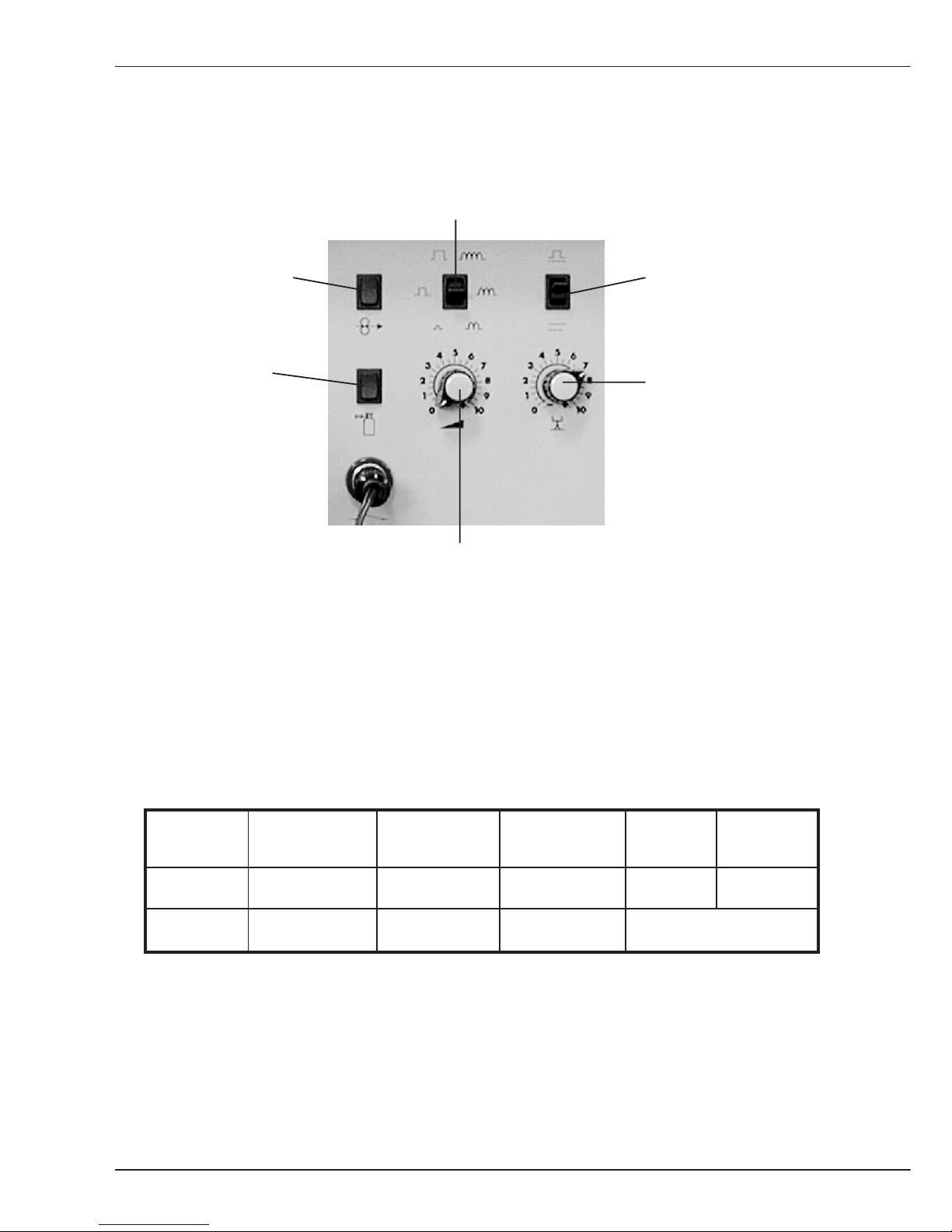
B1.1 Operating and display elements
on the power source
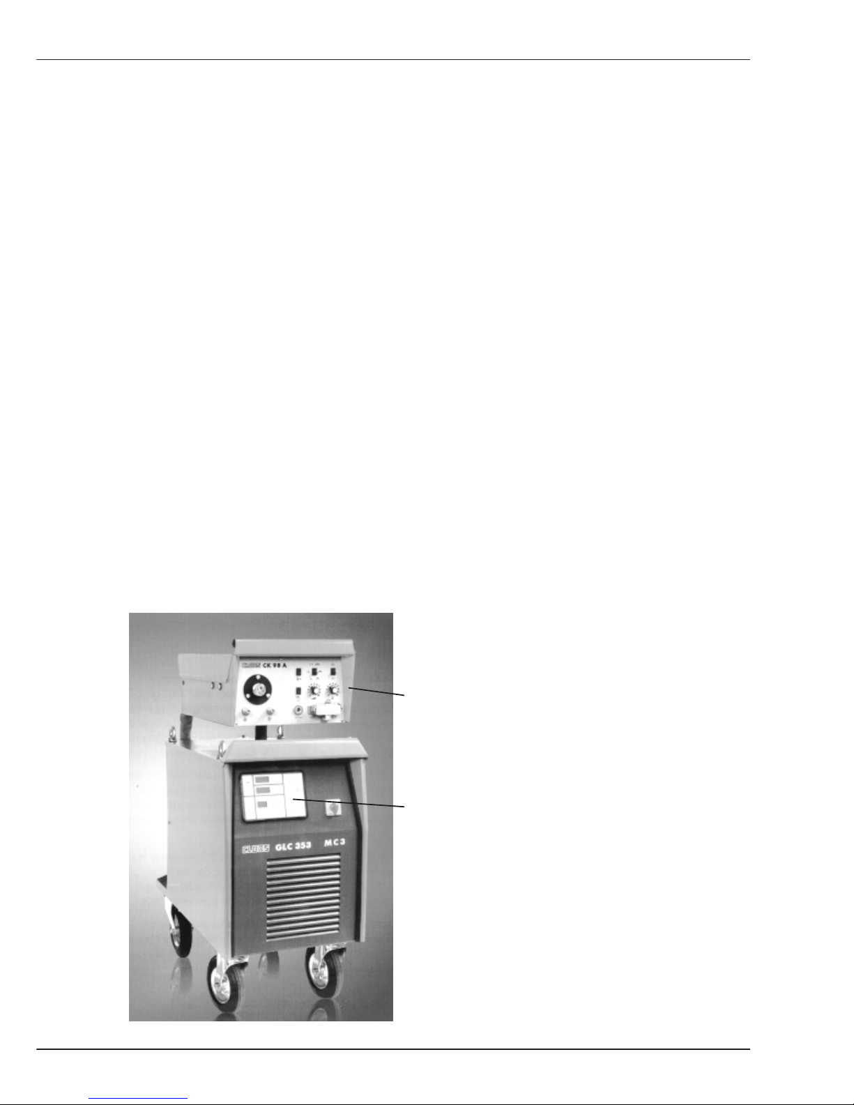
Front view power source
Operating and programming panel
Main switch
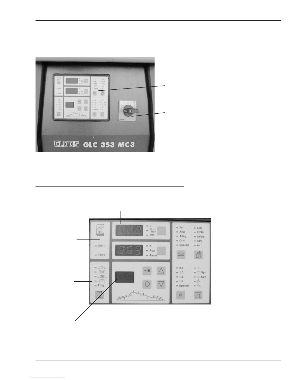
The operating and programming panel is subdivided into:
Display 1 Display 2
Operating modes
Signal lamps
Characteristic
curve selection
Programming
B1.1 Operating and display elements Power source
Display 3
B-5
Operation
GLC 353/503 MC3
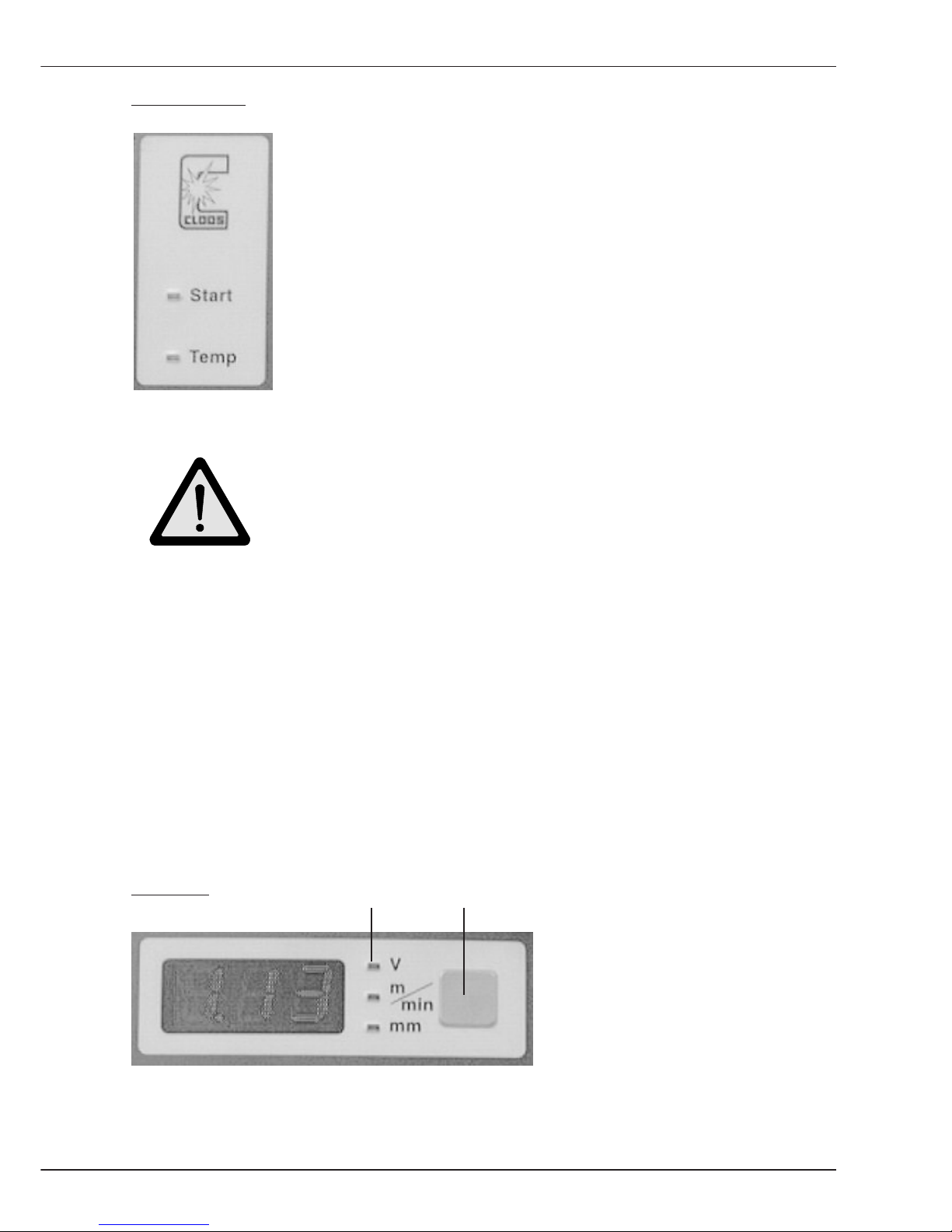
Signal lamps:
The operation panel has two signal lamps:
- Start
- Temp (overtemperature)
Signal lamp Start indicates that the Weld signal was given.
The signal can be given:
- via torch trigger
- externally
- in the operating mode E(lectrode) manual
Caution !
Open circuit voltages exists on connection lugs P and N or on
the welding wire or electrode !
Signal lamp Temperature indicates that the operation temperature of
the following components has been exceeded:
- Welding transformer
- Welding rectifier
- Transistor cascade
- Cooling water pump
- Fan
The welding process cannot be continued if the operating temperature of a component has
been exceeded. Restart is only possible when the overloaded component has cooled
down.
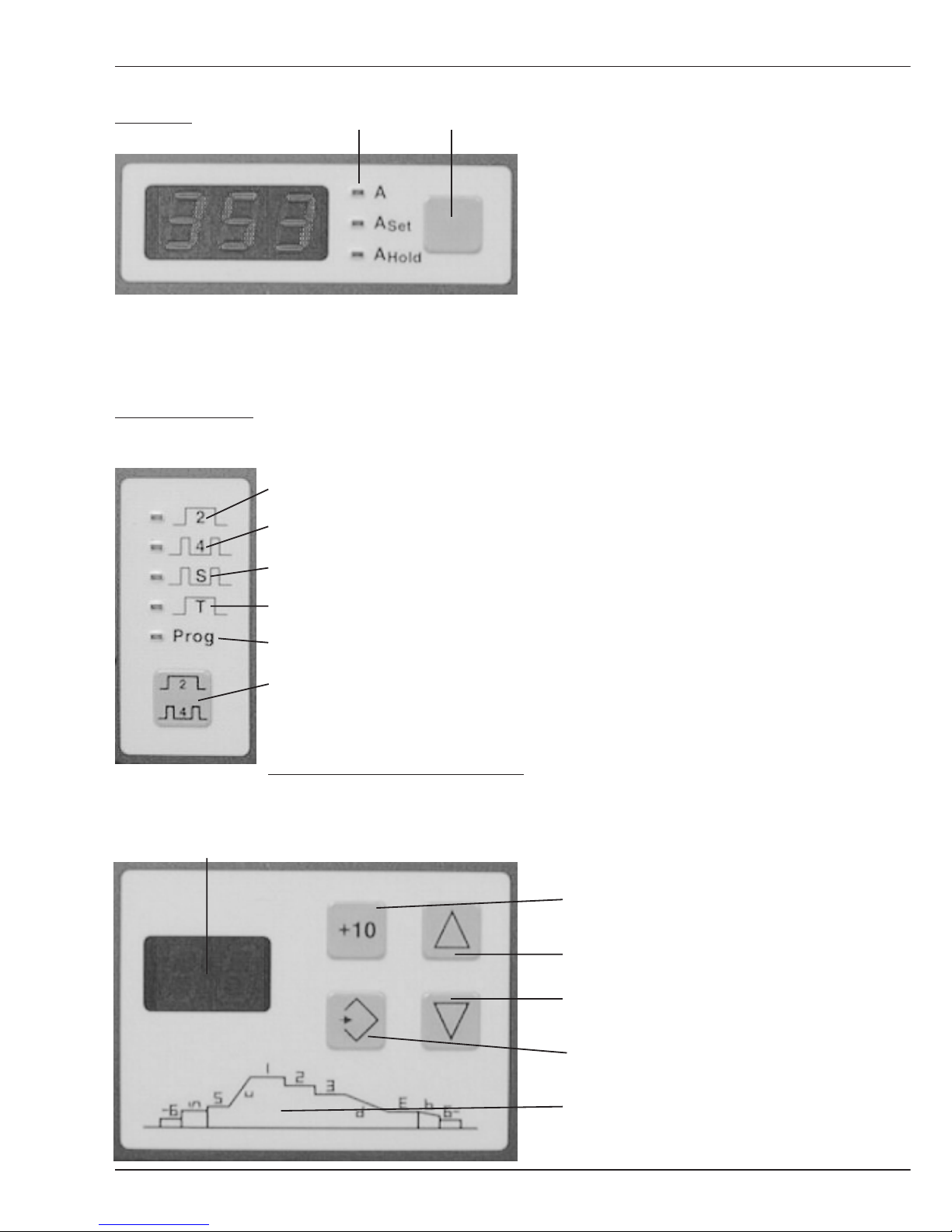
Display 1
The following values are indicated
on the display:
- Welding voltage
- Wire feed speed
- Plate thickness
The value can be selected with the selector key. LED's show the values selected.
LEDs Selector key
B1.1 Operating and display elements Power source
B-6
Operation
GLC 353/503 MC3
Display 2 The following values are shown
on the display:
- Weld current actual value
- Weld current set value
- stored weld current actual
value achieved during last weld
(highest current output)
The value can be selected with the selector key. LEDs show the values selected.
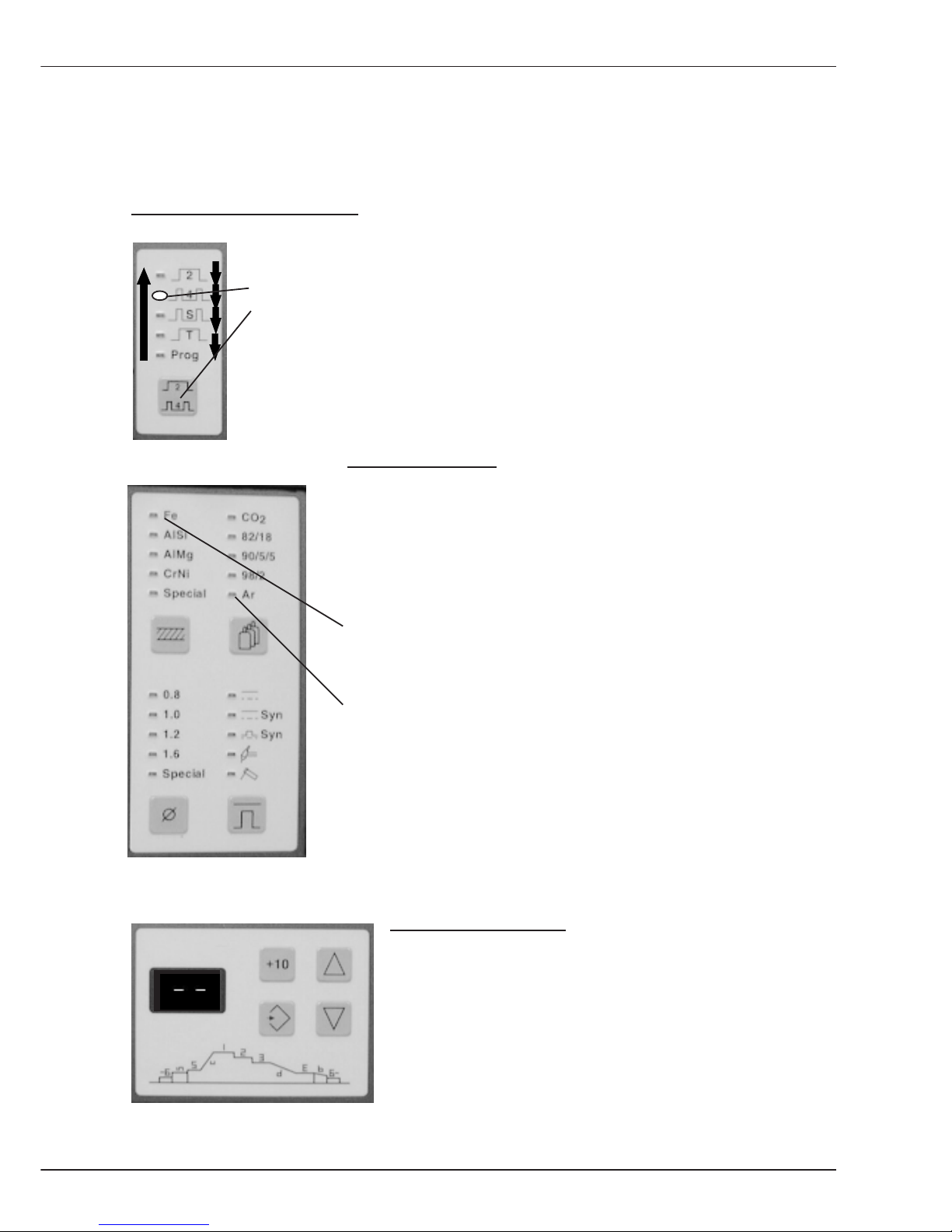
Operation panel:
Press the selector key to select
the required operation mode.
The active operation mode is
displayed by LED.
The operating modes are
described under Definitions.
Press and hold the selector key for
more than a second; the input mode
changes and you can start
programming (see chapter
Programming).
Operation panel programming:
More
information is in the
Display for operating sequence and weld process job No. chapter Programming
Key +10 (change value in
increments of 10)
Key Up
Key Down
Key Store
Diagram for programming
a job sequence
LED's Selector key
B1.1 Operating and display elements Power source
Operating mode 2 cycle
Operating mode 4 cycle
Oper.mode Super 4 cycle
Operating mode spot weld
Operating mode program
Selector key

B-7
Operation
GLC 353/503 MC3
Operation panel characteristic curve:
On this panel the values are set, from which the integrated processor selects a
characteristic curve.
Parameter Material Parameter Gas
Steel CO
2
Aluminium/Silicon 82% Ar, 18% CO
2
Aluminium/Magnesium 90% Ar, 5% CO2, 5%O
2
Chrome/Nickel 98% Ar, 2% O
2
Programming according Pure Argon
to customer requirements
Selector key Material Selector key Gas
Parameter Wire Operation mode
Wire diameter 0,8 (0.030) Normal 2 buttons
Wire diameter 1,0 (0.039) Normal synergic
Wire diameter 1,2 (0.045) Pulsed synergic
Wire diameter 1,6 (1/16) TIG (DC) "Scratch
Start"
Programming according Electrode
to customer requirements
Selector key Wire Selector key Mode
More details on the operation modes and procedures are in the sections Welding and
Definition.
B1.1 Operating and display elements Power source
B-8
Operation
GLC 353/503 MC3
B1.2 Operating elements on the wire drive unit
Switch Pulse adaptation
or choke
Push button Switch With/
Wire manual without pulse
Push button Potentiometer 2
Gas manual Arc length/
(Weld voltage)
Potentiometer 1
Output (wire feed)
During pulse operation the switch 'Pulse adaptation or choke' enables an adaptation of
pulse energy, sometimes required for different cable assembly lengths.
During normal operation this switch 'Pulse adaptation or choke' is used to set the choke
influence.
The table below shows the function of the two Potentiometers, depending on the selected
Procedure.
Procedure Normal Normal Pulse TIG Electrode
2 buttons Synergic Synergic
Poti. 1 Wire feed Output Output Current Current
Poti. 2 Weld voltage Arc length Arc length no function
The Switch without/with pulse is active if the procedure Normal-Synergic or PulseSynergic was selected. You can change over from characteristic curve Normal synergic to
Pulse synergic.
B1.2 Operating elements Wire drive unit
B-9
Operation
GLC 353/503 MC3
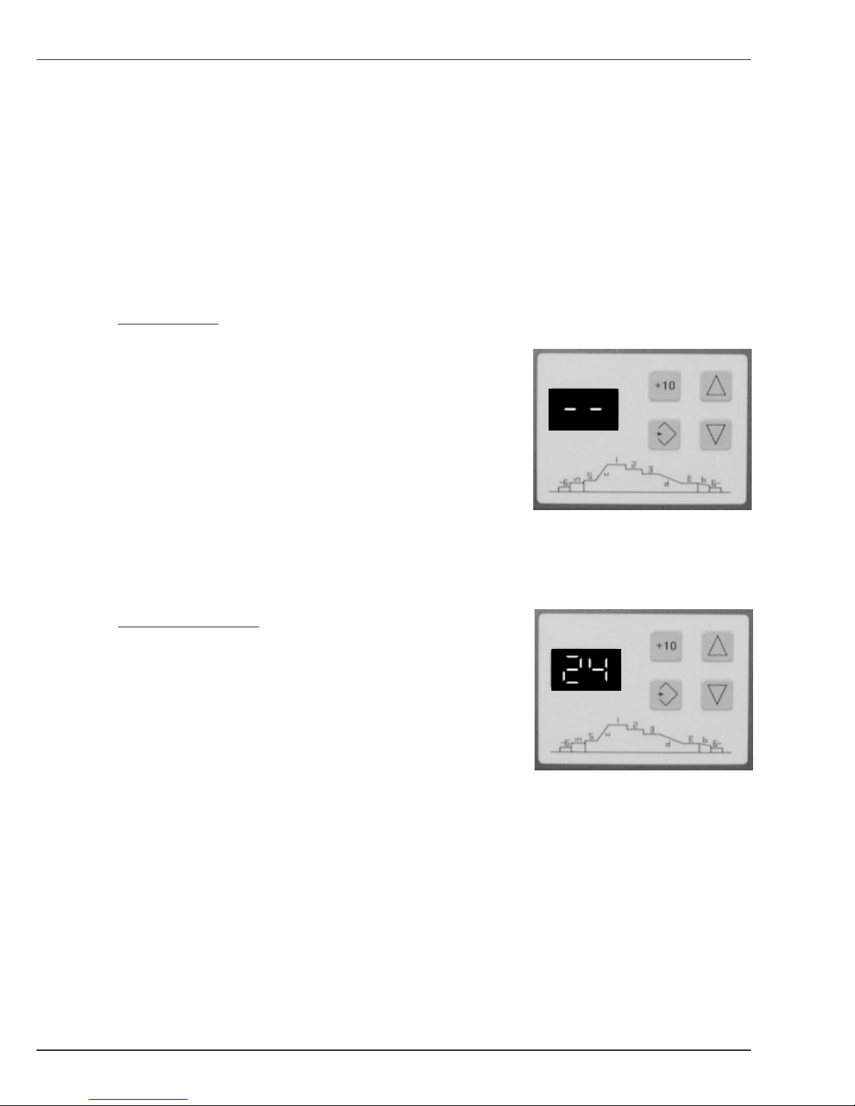
B1.3 Working modes
Display 3 indicates the active mode of the weld power source control.
There are two modes:
- Mode Manual
- Mode Programming
Mode Manual:
If two minus characters are shown on display 3, you can
select all values on the power source operation panel
and start welding. On the wire drive unit operation panel
the arc condition is set via potentiometers 1 and 2.
Welding in this mode is described in chapter B2 welding.
Programming Mode:
If a figure between 1 and 50 is shown on display 3, a stored
weld process job is called up.
In this case welding is carried out with programmed
values.
B1.3 Arbeitsmodis

B-10
Operation
GLC 353/503 MC3
B-11
Welding
GLC 353/503/553 MC3
B2 Welding
B2 Welding
Hereafter please find the operating instructions for the five welding processes.
Please note the following three important instructions:
Operation of selector keys:
Example: You want to select the operation mode. The basic setting is
"operation mode 4 cycle" which is indicated by the
LED. By momentarily pressing the
selector key operation mode the next operation mode is switched on etc.
If the last operation mode is indicated and the key is pressed again, the
display jumps back to the first operation mode.
Flashing of LEDs:
The LEDs flash up in accordance with the combination of
selected values on the operation panel characteristic curve
selection.
This flashing signals that there is no characteristic curve
available for this setting. In our example, the values
Steel
and
Argon
have been set. There is no characteristic curve for a
combination of these values because welding is not possible
with this setting.
Select mode manual:
For the following explanations it is required to set the power
source to mode manual.
Please proceed as follows:
When a number appears on display panel 3, press the key
Down until two Minus signs light up.
Mode manual is switched on now.
B-12
Welding
GLC 353/503/553 MC3
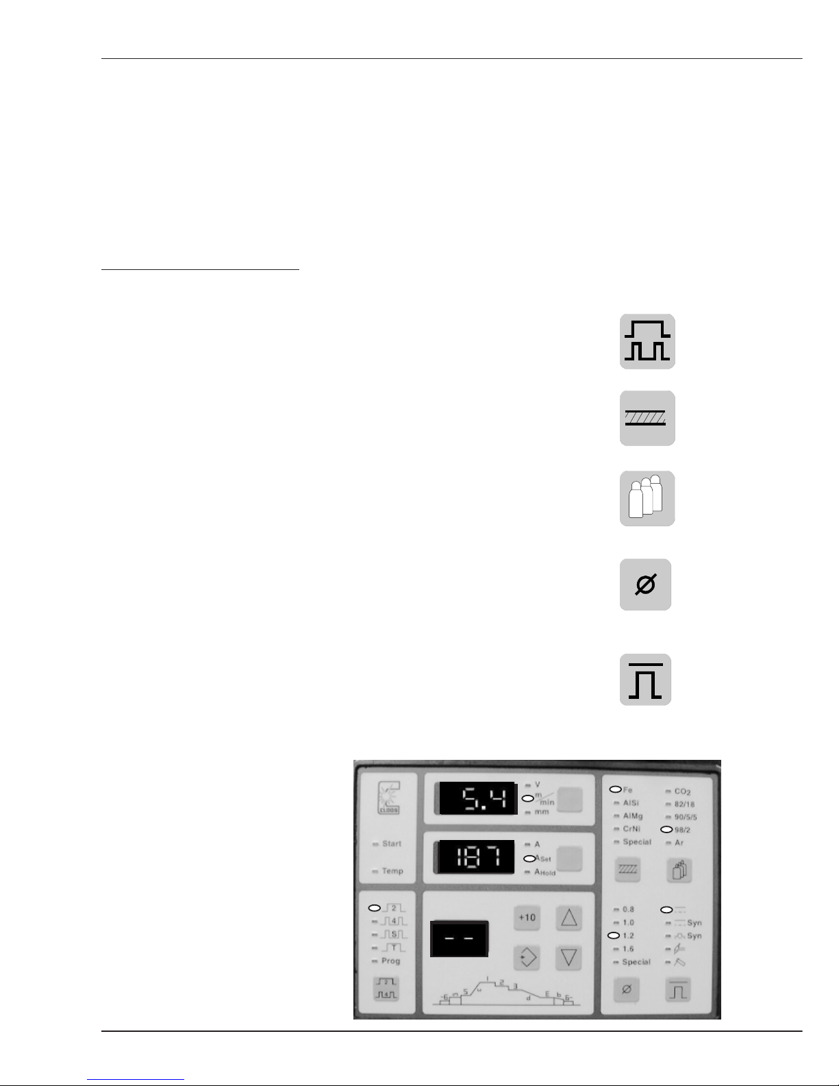
B2.1 MIG-MAG Normal 2 knob
B2.1 Procedure: MIG-MAG Normal 2 knob operation
The following instructions inform you how to use the power source with 2 knob operation,
without internal characteristic curve.
The welder determines the characteristic curve and the working point on the characteristic
curve with the values wire feed speed and weld voltage. After setting the processvalues at
the power source operation panel, the values wire feed and weld voltage are selected at
the wire drive unit operation panel.
Please proceed as follows:
- Switch machine on
- Select the Operating mode by pressing the key.
In our example the operation mode 2 cycle has been set.
- Set the Material to be welded:
In our example Steel is used.
- The Gas used has to be set with the following key:
Mixed gas is used, consisting of 98% Argon and
2% CO2 .
- Set the Wire diameter with the following key:
In the example 1,2 mm diameter welding wire
is used.
- Select the Procedure by pressing the following key:
When welding with 2 knob operation without pulse, the upper
LED flashes (see photo).
- Set the Display 1
by pressing the selector
key until m/min for the wire
feed speed is highlighted.
After setting, the LEDs light up as
shown on the photo.
 Loading...