

Page 1

16
GLC 353/503/553 MC3Operating instructions
GLC 353 MC3
GLC 503 MC3
GLC 553 MC3
MIG/MAG Welding Machine OPERATING INSTRUCTIONS
and SPARE PARTS LISTS
PLEASE KEEP SAFELY FOR FUTURE REFERENCE
128/01.01
CARL CLOOS
Schweißtechnik GmbH
Industriestr. • 35708 Haiger
Tel. +49 2773/85-0
Fax. +49 2773/85-275
http://www.cloos.de
[email protected]
Page 2

Page 3

1
GLC 353/503/553 MC3Operating instructions
Operating Instructions
MIG/MAG Welding Machine
GLC 353 MC3
GLC 503 MC3
and
GLC 553 MC3
with
CK 98 A Wire Drive Unit
Print No.: 128
Issued: 01/01
Subject to technical alterations
Page 4

2
GLC 353/503/553 MC3Operating instructions
W A R N I N G !
Prior to the first commissioning, all persons who are involved with
this machine should read this operating instruction manual
carefully and confirm that they have done so in writing.
Please keep the operating instruction manual easily accessible for
all welders and service staff!
The best place is the welding machine itself!
Page 5

3
GLC 353/503/553 MC3
Operating instructions
EN50199:1995
Appendix A (information)
Installation and use
The user is responsible for the installation and operation of the welding machine according to the manufacturer's
instructions. If there is electromagnetic interference, the user is responible for finding a solution with the aid of
the manufacturer of the welding machine, e.g. grounding of the weld current circuit, electromagnetic screening
and/or inlet filter.
A.1 Evaluation of the area
Before installing the welding machine, the user has to evaluate any possible electromagnetic problems in the
surrounding area. The following must be taken into consideration:
a) Other mains supply lines, control lines, signal and telecommunication lines above, below and next
to the welding machine.
b) Radio and TV broadcasting station and receiver.
c) Computer and other control units.
d) Safety devices, e.g. protection for commercial equipment.
e) Health of persons in vicinity, e.g. if using pacemakers and hearing aids.
f) Units for calibration or measement.
g) Resistance to interference of other equipment in the surrounding area. The user must ensure that
other equipment used in the vicinity is electromagnetically compatible. This may require additional
safety measures.
h) The time of day when welding or other activities are being carried out.
The extent of the surrounding area to be considered depends on the construction of the building and other
activities which take place there and may exceed the boundaries of the property.
A.2 Procedure to reduce emissions
A.2.1 Mains supply
The manufacturer recommends that the welding equipment is connected to the mains supply. Where there is
some interference, additional safety precautions may be necessary, i.e. filter for the power supply.
A.2.2 Maintenance of the welding equipment
Regular maintenance intervals are recommended by the manufacturer.
A.2.3 Weld cables
Welding cables should be as short as possible and should be run close together on or near to the floor.
A.2.4 Potential equalization
The electric connection of all metal parts in and near a welding machine should be taken into account. The metal
parts connected to the workpiece may increase the risk of an electric shock if the welder touches these metal
parts and the electrode at the same time. The welder should be protected against all connected metal parts.
A.2.5 Earth connection of workpiece
It must be ensured that earthing of the workpiece does not increase the risk of accident to the user or causes
damage to other electrical equipment.
A.2.6 Screening
Selective screening of other cables and equipment in the vicinity may reduce electrical interference. Screening
of the complete welding equipment may be considered in special situations.
5/96
Page 6

4
GLC 353/503/553 MC3Operating instructions
Page 7

5
GLC 353/503/553 MC3
Operating instructions
Safety specifications..........................................................................................7-9
Particular information for welding ..............................................................................7
Technical data .............................................................................................9
General product description ................................................................................ 10
Operating instructions ................................................................................... 10-13
Transport ...........................................................................................10
Mounting area, floor requirement, environment ..................................................... 10
Storage ...........................................................................................11
Assembly ...........................................................................................11
Power supply ...........................................................................................11
Torch connection, earth cable ...............................................................................11
Shielding gas, reducing valve................................................................................11
Wire drive ...........................................................................................12
Coolant ........................................................................................... 12
Commissioning ...........................................................................................13
Special safety devices......................................................................................... 13
Temperature protection ......................................................................................... 13
Overload protection ...........................................................................................13
Operation / Service ...........................................................................................13
General instructions for shielded gas welding ............................................13-14
Instructions for welding...................................................................................... 15
Operation......................................................................................B-1-44
Mechanical description ............................................................................... L- 1-24
Illustrations welding machine GLC MC 3..............................................................2-5
Spare parts list GLC MC 3....................................................................................6-7
Illustrations wire drive unit CK 98 A......................................................................8-9
Spare parts list CK 98 A........................................................................................10
Sectional drawing: 2 + 2 roller system with central connection..............................11
Spare parts list 2+2 roller drive compl. with central connection
for steel and flux cored wire.............................................................................. 12-13
Sectional drawing: 2 + 2 roller system with central connection.............................. 14
Spare parts list aluminium equipment for 2+2 roller drive with central connection ..... 15
HD Drive ..........................................................................................................16
Spare parts list HD Drive ..................................................................................17-18
Sectional drawing cable assembly for CK 98 A ..................................................... 19
Spare parts list cable assembly CK 98 A............................................................... 20
Sectional drawing cable assembly for CK 98 A, cable assembly connectable ...... 21
Spare parts list cable assembly CK 98 A, cable assembly connectable................22
Sectional drawing wire coil holder compl...............................................................23
Spare parts list for wire coil holder compl. ............................................................. 24
Electrical description ................................................................................ L- 25-53
Circuit diagrams GLC 353 MC 3.......................................................................25-27
Electrical parts list GLC 353 MC 3.................................................................... 28-33
Circuit diagrams GLC 553 MC 3.......................................................................34-36
Electrical parts list GLC 553 MC 3.................................................................... 37-40
Circuit diagram CK 98 A ........................................................................................ 41
Electrical parts list CK 98 A .............................................................................. 42-43
Circuit diagram CK 98 A with installation kit remote controller socket ..............44-45
Electrical parts list CK 98 A .............................................................................46-47
Circuit diagram CK 98 A, cable assembly connectable ................................... 48-49
Electrical parts list CK 98 A, cable assembly connectable ..............................50-51
Circuit diagram remote controller .......................................................................... 52
Electrical parts list remote controller...................................................................... 53
APPENDIX
Supplement cooling water device .......................................................................... 51
List of addresses - CLOOS representatives in Germany/abroad ..................... A1-A4
INDEX
Page 8

6
GLC 353/503/553 MC3Operating instructions
Page 9

7
GLC 353/503/553 MC3Operating instructions
Safety specifications
General information
Warning!
This is a class A equipment which may cause radio
interferences in residential areas. In such a case the
operator may be asked to take adequate steps on his
account.
The GLC 353/503/553 MC3 machine with CK 98 A is
built according to EN 60 974-1. It corresponds to the
latest "state of the art" engineering and its reliability
is proven. It must be operated by trained personnel in
accordance with the following instructions to provide
safe and efficient operation.
The machine is not suitable for thawing
pipelines due to Fire risk !
Flammable gases or gases which induce a chemical
reaction, such as Acetylene, Propane, pure Hydrogen, pure Oxygen are prohibited.
Please note the following!
- Safety regulations VBG 15
- Safety regulations VBG 4
- Fire protection rules
- Welding and maintenance to be carried out by
qualified personnel only.
- The machine must be switched-off and
disconnected for all maintenance work.
- Repair of electronics to be carried out by service
personnel only. If repair work is carried out by
unauthorized persons and safety regulations are
not adhered to, the warranty becomes invalid.
This welding machine is intended for industrial use
and must not be used in residential buildings.
As >16 Amp are required per phase, this machine is
subject to the IEC 61000-3-4 standard or EN 61000-312, when it is available. In order to avoid
electromagnetic interference (EMI), certain conditions
must exist (size of mains impedance) for connection
to the public low voltage network. Please inform the
relevant electricity supplier about this machine’s
connection. Please do not hesitate to contact your
Electricity supplier or the manufacturer if you need
help or information.
Particular information for welding
Personal protection (rays, gases, vapours)
— When welding, dry protective clothing, apron,
helmet and gloves as well as solid work shoes
should be worn.
— Use a protective shield or helmet with glass, with
DIN marking, outside clear, inside tinted.
— Protect other persons in the vicinity of the
welding area from UV rays and spatter by
suitable, non-flammable partition walls.
— Always wear safety glasses if you are in an area
where welding takes place.
— Wear safety glasses with side protection when
you are welding or when removing slag.
— Caution! UV rays are released during welding.
Protect body and particularly the eyes. Keep
protective ointment and eye drops available.
— All metal vapours are toxic! Be careful with
alloys which contain lead, cadmium, copper,
zinc, nickle, chrome, berillium.
— Parts, cleaned with chlorinated agents, cause the
toxic gas phosgen to form in the arc.
Caution Risk of poisoning in narrow places !
If shielding gas hoses are not tight or the
shielding gas valve gets caught unintentionally,
shielding gas may escape to such an extent that
the oxygen content of the inhaled air decreases;
symptoms of poisoning appear which may lead to
unconsciousness and suffocation. Sufficient fresh
air must be provided! Please check the gas
supplying parts at regular
intervals.
Fire prevention (explosion)
— Remove all flammable materials around the
welding place or cover these with a nonflammable material.
— Hot slag or spatter might cause fires if in contact
with flammable materials.
— Only use shielding gases suitable for welding,
such as Argon, CO2 and Argon and CO2 or
Argon, CO2 and O2 mixtures.
Never use flammable gases like Acetylene,
Propane, Hydrogen or fire supporting gases such
as Oxygen.
— Never weld on drums, tanks or similar containers
unless they have been thoroughly cleaned and
you are sure that no toxic, flammable or explosive vapour can develop.
— Fire fighting agents such as water or sand or a
fire extinguisher should always be available.
— Confined spaces must have a free passage
allowing escape in case of danger.
— Please observe the weld area and its
surroundings when welding has finished. Fire
may break out later due to smoldering.
Electrical danger (current, voltage)
Pacemakers
Wearers of pacemakers may potentially by at risk
from arc welding. When MIG/MAG welding the risk is
from magnetic fields and when TIG welding from high
voltage pulses of the arc ignition units.
Page 10
8
GLC 353/503/553 MC3Operating instructions
As there are several versions of pacemakers, the
situation must be clarified with the relevant
pacemaker manufacturers or their representatives
(hospital etc.).
— Switch off the welding machine when not in use
to prevent any electrical risk.
Warning! The terminal voltage of the welding
machine may be up to 113V= or 48V~!
— If you have to stand on metal or in a wet area
during welding, insulation with suitable dry
materials is required.
— Avoid contact with wet or conductive metal parts;
wear dry clothing.
— Always maintain correct insulation of cables,
plugs and welding torches. Do not overload
these parts.
— Keep everything dry, including clothing, welding
area, cables and welding machine. Repair
immediately any faulty water cooling lines.
— Welding machines may only be used if all covers
are present and correctly installed.
— Although the machine is marked “S” (approved
for welding in environments with increased
electrical hazard), the power source itself may
not be installed here, because of the mains
voltage of 400 V; only the welding torch and the
wire drive unit are permitted at such places.
— Before any work is carried out inside the power
source, the mains switch must be switched-off
and the mains plug disconnected.
After disconnecting the mains plug, wait at least
2 minutes until the capacitors have reached safe
values.
— Be careful when changing the wire coils. Switch
off the machine so that the switching command
cannot be initiated.
— Lock the wire coil holder, by turning the locking
button to prevent the wire coil becoming loose.
Page 11

9
GLC 353/503/553 MC3
Operating instructions
Technical data:
GLC 353 MC3 GLC 503 MC3 GLC 553 MC3
Input:
Nominal input voltage 3x400V ac 3x400V ac 3x400V ac
Nominal frequency 50Hz 50Hz 50Hz
(Other voltage and 60 Hz frequency are available upon request)
Input - peak current 23A 37A 47A
Input - continuous current 19A 27A 40A
Slow blow fuse 25A 35A 50A
Power supply cable 4x4mm
2
4x6mm
2
4x10mm
2
Input constant power 13.1kVA 18,7kVA 27,7kVA
Power factor cos Phi 0.92 0,96 0,96
Output:
Max. open circuit voltage 56V 70V 70V
Welding range for MIG/MAG 40A/15V-350A/40V 40A/12V-500A/42V 40A/12V-550A/
44,5V
Duty cycle 100% 300A/29V 400A/34V 500A/39V
Duty cycle 60% (10min.) 350A/31.5V 500A/39V 550A/41,5V
Type of protection IP 23 IP 23 IP 23
Type of cooling F F F
Insulation class F (1550C) F (1550C) F(155°C)
Dimensions LxWxH power source 960x460x930mm 1190x530x930mm 1190x530x930mm
Weight of power source 153kg 220kg 220kg
Dimensions LxWxH wire drive unit 610x380x355mm
Weight wire drive unit 22kg
Torch water cooling 2.0 l/min. at 3.0 bar (30m Ws)
Continuous noise level 1 m a height of 1.6 m and a distance of 1 m from the machine:
Machine noise when switched on 58 dB (A) 60 dB (A) 68 dB (A)
Arc noise at max. output 80 dB (A) 82 dB (A) 85 dB (A)
according to DIN 45 635, part 1
Wire feed infinitely adjustable 0 ... 24m/min. 0 ... 30m/min. 0 ... 30m/min.
Permission EN 60 974-1
The machine is designed for manual MIG/MAG welding of all metals.
Manual DC-current TIG welding with lift-arc ignition is possible.
All coated stick electrodes can be welded.
- The machine corresponds to the machine rules (98/37/EG), the low voltage rules
(73/23/EWG) and the rules for electromagnetic compatibility(89/336/EWG).
- The machine is approved for welding in environments with increased electrical hazard and is marked with
the letter „S“.
Page 12

10
GLC 353/503/553 MC3Operating instructions
Shielding gases
The following gases are used for MIG/MAG welding:
Pure Argon, CO2, mixtures of Argon and CO2 or
Argon, CO2 and O2.
Flammable gases or gases which induce a chemical
reaction such as Acetylene, Propane, pure Hydrogen, pure Oxygen are prohibited.
Operating instructions
Transport
The machine must always be transported without
gas cylinder.
All cables must be wound up and put on the machine
before transport.
The machine can be moved on its wheels. When
using a fork lift truck, the forks must be applied
between the wheels. The machine must lie
crosswise on the truck.
Transport by means of a crane is also possible. If
jack rings are available all of them must be used
because of the carrying capacity and load
distribution. If there are no jack rings, two belts must
be used, pulled crosswise under the machine inside
the wheels.
Mounting area, floor requirement,
environment
- The machine should be installed on a horizontal,
flat surface, dust-free and well ventilated.
- The distance between other machines or
buildings should at least be 0.50 m (24 inches on
all sides, to aid ease of servicing.
- The cooling air entrance and exit grills must not
be restricted in any way
- The ambient temperature may vary from -100C
to +400C .
- The machine is protected to IP 23 which does
not permit use in the rain. If necessary, it should
be covered. In this case ensure that the cooling
air flow is not affected!
- The machine is marked "S", which means
approved for welding in environments with
increased electrical hazard; however, the power
source itself must not be installed there due to
the mains voltage of 400 V; only the welding
torch is permitted in such places.
General product description
Application possibilities and
restrictions
The transistorized MIG/MAG pulsed arc welding
machine type GLC 353/503 MC3 with wire drive unit
type CK 98 A is a welding machine with micro computer
control and a new air cooled power part with extremely
quick regulation due to particularl switch controller
technology. Outstanding welding features and low power
losses result from this. Aimed drop deposition with a
highest possible spatter reduction when welding with
Argon and Argon rich mixed gases with max. 20% CO
2
part. It can be welded pulse free with all arc kinds under
Argon, Argon O2 mixed gases with multicomponent
mixed gases and under pure CO2.
Remarkable features of the wire drive units are the
precise rotation control (tacho control) and high motor
power (100 W) with four quadrant regulation (D).
2 + 2 roller system and 4 roller system guarantee safe,
slip-free and low abrasion wire transport. The adjustment
of the counter pressure is reproducible and comfortable
in handling.
The arc burns between wire and workpiece under
shielding gases (MAG = Metal active gas and MIG =
Metal inert gas procedure).
The wire electrode continuously unwound off the reel
until a reel is used up. The coil weight is 15 kgs with
steel and 4 ... 5 kgs with Aluminium.
The wire thickness and welding torches to be used
depend on material thickness and seam shape.
Power sources and wire feed are in separate housings
connected by a cable assembly. The complete system
is mounted on four rubber tyred wheels.
The machine is connected to a three phase current
supply. Direct current is available at the outlet.
The machine is set up for manual, mechanical and
robot MIG/MAG welding all metals. Manual d.c. TIG
welding with lift-arc ignition is possible.
The machine is suitable for welding all kind of flux cored
wire electrodes.
The machine is not suitable for thawing pipelines.
- Fire risk! -
Page 13

11
GLC 353/503/553 MC3
Operating instructions
Storage
- The machine should be stored indoors at a
temperature between -100C and +400C and
should be covered.
- If the coolant is not emptied, please ensure that
an anti-freeze agent is added. The coolant must
be disposed of and must not enter the main
drainage system.
Assembly
A complete machine comprises:
1. Transistorized MIG/MAG pulsed arc
welding machine type
GLC 353/503MC3
2. Wire drive unit type Typ CK 98 A
3. Cable assembly, connectable
4. MIG/MAG welding torch
5. Standard accessories including:
Earth cable
Reducing valve with l/min.-scale
Tools
Set of fuses for power source
6. Options, if required
The individual components, MIG/MAG welding
machine, connectable cable assembly, wire drive
unit, gas cylinder and reducing valve have to be
assembled. The water hoses must not be
exchanged. The flow is marked blue!
Make sure cooling liquid is sufficiently filled.
All water-cooled machines are supplied with a 5 litre
container of ready-to-use mixture.
Power supply
The power supply must be installed by qualified
personnel only!
Please ensure that the mains voltage to be used is
identical to the operating voltage indicated on the
machine type plate.
According to the connection regulations the machine
has to be connected by means of a mains cable. The
power supply must be fused according to the
connection regulations. To ensure good welding
performance the cross section of the connection
cable must be adequate.
The phases L1, L2, L3 and PE are connected. The
neutral wire (N) remains free.
A correct conductor connection must be provided!
(VDE regulations).
Torch connection, earth cable
- The welding torch is connected to the central
connection, item 13, the water hoses to the
connections items 119 and 120 - they must not
be exchanged (insufficient cooling of the welding
torch). The flow is marked blue. The control line is
connected to the socket, item 109.
- The earth cable is connected to the current
connection, item 79, and locked by turning right.
- The gas cylinder is placed on the base plate, item
87, at the rear of the machine and is secured by a
chain, item 87/2, which is connected to the
holder, item 87/1.
Shielding gas, reducing valve
— The reducing valve is screwed onto the gas
cylinder and connected to the machine by means
of the gas hose, item 215. The gas quantity is
adjusted at the reducing valve. For this purpose
the machine must be switched on and the torch
button or key “gas manual”, item 103 must be
actuated at the wire drive unit.
— The normal gas quantity for Argon and mixed
gases is 8 - 15 l/min. and for CO2 10 - 20 l/min.
— In general, carbon dioxide with a percentage
purity of 99.9 % is used for welding with
unalloyed or low alloy steels with a strength of 37
- 60 kgs. In Germany the gas cylinders have the
additional marking “S” (= Schweißzwecke welding purposes).
These steels can be welded with the gas mixture
(AR + CO2 + O2), high alloy steels, e.g. chrome
nickel steel require protective gas K2 ( Ar + 2%
CO2). Aluminium and other nonferrous metals
require pure Argon 99.9 %.
— The flow quantities indicated on the extraction
manometer depend upon choke setting, item
113/2 in front of the gas valve, item 111. This
choke has a nominal diameter of 0.6 mm. The
nominal diameter size 0.6 is clearly marked on
the litre scale of the extraction manometer. For
example, in the case of 4 bar, the flow quantity is
11.5 l/min.
— In the case of ring mains which operate at less
pressure, it is not possible to set a flow quantity
Page 14

12
GLC 353/503/553 MC3Operating instructions
of 11.5 l/min. In this case the choke diameter has
to be enlarged from 0.6 to 2.0 mm or the gas
retaining unit, item 113 exchanged for item 113 a,
so that a greater flow is created at a lower
pressure.
— If the original flow meter is not connected, the
flow quantity at the gas nozzle of the welding
torch must always be checked with a suitable
flow meter.
— A simple gas flow measuring tube is available
under ref. No. 097 03 04 00.
Wire drive
Wire drive rollers, item 18, wire guide unit, item 10 and
wire inlet nozzle, item 15 are marked according to the
wire size, to prevent wrong nozzle size being used by
mistake. This also applies to the contact tips and liners
of the welding torch, which are also marked with the
wire sizes.
When changing the wire drive rolls and gear wheels,
force must not be used to mount them on the gear
shafts, e.g. hammer or similar because this might
cause damage.
Prior to installation, all parts must be cleaned and except the drive rolls - be greased.
The welding wire itself is threaded inside the wire drive
unit throughout the wire guide spiral, item 12, the wire
drive rollers, item 18, the wire guide piece, item 10, and
the wire inlet nozzle, item 15. The wire is transported to
the torch by actuating the torch button wire manual,
item 104 on the wire drive unit. To do this the machine
must be switched on. The pressure arms, item 7 and
item 8 must only be sufficiently pressed against the
pressure units as is necessary for the relevant wire type
and size. The adjustment is reproducible. The pressure
arms swing out for threading the wire or exchanging the
wire drive rollers. The two pressure units, item 9, have
to be adjusted equally.
The pressure units of the pressure roller brackets
must not be set at more than -3-
The brake of the wire coil holder can be adjusted with
the tightening screw, item 8. The wire coil should not
move when the motor brakes, to prevent wire windings
falling off the coil and kinking or short circuits occurring.
If the brake no longer works, the brake disk, item 7 must
be replaced!
The wire coil must be secured on the wire coil holder
with the locking button, item 2, to prevent it falling off.
Coolant
As soon as the welding torch is connected, the coolant
can be filled into the cooling system. It is absolutely
essential that distilled water is used! Do not use
chlorinated water or water with a high mineral content
because of its electrical conductivity. The cooling system
cannot be completely emptied. Therefore, to avoid
damage from frost, an anti-freeze agent must always
be added, which also protects against corrosion. Only
use Glykorol EL. CLOOS ref. No. 000 01 01 22!
A five litre container of a ready-to-use mixture of: two
parts distilled water and one part Glykorol EL
(up to - 20° C) is supplied with each water-cooled
machine. CLOOS ref No. 000 01 01 31.
The water container is filled via filling connection,
item 86. A certain vacuum must remain so that the
cooling liquid can return during water blow through
without overflowing. The drain cock, item 93, at the
rear of the machine must then be opened until the
coolant flows out. The water pipes are thereby
vented and coolant is brought to the pump.
WARNING! Avoid dry-running of the pump, even
for a short period! Otherwise the shaft seal may
be damaged.
With regard to the construction of the pump it is
important that the cooling liquid is absolutely clean.
Impurities such as sand or swart as well as sticky
residues, lubricating grease etc. may damage the
pump.
Be careful after torch repairs !
Danger! Glykorol EL
is dangerous if swallowed and
harmful to skin! Carefully wash
your hands after filling!!
Safety precaution!
Keep out of reach of children.
The water hoses are filled when the machine runs.
When using very long cable assemblies, the resulting
loss of water in the cooling water container must be
replenished. Please note the max. coolant quantity!
Page 15

13
GLC 353/503/553 MC3
Operating instructions
Special safety devices
Temperature protection
The main transformer, main rectifier and
transistor cascade are protected from
overheating by thermal switches which cut off
the welding command. This is indicated by a
yellow control lamp and as plain text on the
display. The machine should remain switched
on so that cooling air can continue cooling.
Overload protection
The cooling fan and water cooling pump are
protected from overheating by thermal
switches. Overheating can be caused by
overcharging the motor windings. The thermal
switches cut off the welding command and the
tension from the motor winding. This is
indicated by a yellow control lamp and as plain
text on the display.
Switch the machine off and eliminate the
cause for overheating.
Service
The machine can be commissioned when the
welding machine, cable assembly, wire drive unit,
welding torch, earth cable, shielding gas cylinder with
reducing valve and welding wire have correctly been
connected and installed.
- It should be ensured that the flow and return
water hoses of the wire drive unit and the torch
are not mixed up (insufficient torch cooling). The
flow is marked blue.
- The cable assembly must be protected from
tension on the power source with the enclosed
hose clip on the upper part of the cylinder holder.
- The cable assembly must be protected from
tension of the wire drive unit at the baseplate with
the second hose clip.
The tank cap must always be screwed down to
prevent contamination of the cooling liquid!
The welding machine must always be switched off
when the torch cooling circuit is interrupted, for
example when the welding torch is removed. 'The
water connections then shut automatically to prevent
the coolant running out. The pump produces a
dynamic pressure of 3,8 bar. If this pressure exists
for a long period, the pump and the coolant heat up
to such an extent that damage and leakages may
occur.
WARNING!
The machine is provided with a water filter in front of
the suction side of the cooling water pump.
When the message "lack of water" occurs, this filter
must be checked for impurities, be removed, washed
and reinstalled.
Do not change the mounting direction! Arrow head
away from pump ! Do not install a water filter without
a flow control switch.
Water cooling device
When welding at high ambient temperature (greater
than 40°C) with high capacity (greater than 500 A)
it is recommended that the cooling water for the
torch is cooled by a separate water cooling device,
i.e. ST 157/2. This device prevents the ambient air
being warmed up by the components which are
being cooled, as is the case with an integrated
water cooling system.
Commissioning
The machine is switched on with the mains switch,
item 42.
Pum and fan are switched on after approx. 10 s for 1
minute. The cooling air is suctioned at the front side
and blown out at the rear side (gas cylinder).
Interval switch off for pump and fan!
Pump and fan are only switched on when welding.
After welding they run for approx. 5 more min. in
order to recool accordingly. This avoids that in the
case of longer downtimes dirty cooling air is sucked
into the machine. Furthermore, noises and current
consumption are reduced.
The GLC 553 MC3 fan is provided with two power
steps. Normally, the low step I is switched on. If
cooling is not sufficient, the stronger step II can be
used.
Page 16

14
GLC 353/503/553 MC3Operating instructions
General instructions for shielded gas
welding
With MIG/MAG shielded arc welding machines both
short arc and spray arc can be used.
Short arc is also called “dip-transfer arc”. When using
the short arc procedure, there is a relatively low welding
density on the welding wire so that the additional
material passes on to the workpiece in the shape of
individual drops (approx. 50 - 80 drops per second).
The heat input itself is relatively low so that with this
method thin sheet as well as root and vertical up seams
with thicker plate can be welded (also awkward position
welding).
With the spray arc technique a high current density is
used on the wire cross section. The welding material no
longer passes in drops onto the workpiece but as a
spray. Wherever an adequate welding performance as
regards the fusion quantity is required, the spray arc
process is the only one to consider.
At less than approx. 180 Amps/mm2 current density
with steel wire short arc welding is generally considered,
whereas with more than 200 Amps/mm2 the spray arc
technique starts to be used. The transition from short
arc to spray arc varies according to the different kind of
gases.
Using CO2 as shielding gas, deep penetration is a
feature with steel welding, whereas, Argon S 5 (Ar +
5 % O2) for example gives only slight penetration. Using
gas mixtures (normal ratio about 90 % Ar + 5 % CO2 +
5 % O2) penetration lies somewhere between the two
above gases.
Due to the deep penetration when using CO2, the
wedge angle must not exceed 30 - 40°. Less welding
material is therefore required on the one hand and on
the other, the welding efficiency is increased.
In the case of thin sheet, up to 3 mm maximum, the
vertical down seam position is advisible, as this results
in a higher welding speed and the surface appearance
of the seams is also improved.
High alloy steels are welded using protective gas K2 (Ar
+ 3% CO2).
Non-ferrous metals such as aluminium, copper, bronze,
etc. are welded with pure Argon 99.9% or gas mixtures
consisting of Argon and Helium (65 % Ar + 35 % He).
In the case of copper welding it is also necessary to
preheat the workpiece from 4 - 5 mm thickness upwards
to coat the welding edges with a deoxidizing paste.
During welding the welding torch must be held at an
angle of 5° towards the vertical of the workpiece. The
tip is approx. 15 mm away from the workpiece wire
diameter.
Special instructions for pulsed arc
welding
Spray arc
Using Argon or Argon mixtures with less than 20% CO
2
and sufficient high power and voltages the material
transition is carried out freely in the form of small drops
or drop chains without short circuit formation. Therefore
a spatter free welding is possible with the spray arc. A
precondition is, however, the use of the above shielding
gases. Due to the high energy input and the high
deposit efficiency this technique is only used - similar to
the semishort circuiting arc weldment - for the filler and
cover pass welding in the w- and h-position.
Pulsed arc
The short-circuit free material transition of the spray arc
is made use of by the pulsed arc technique. The energy
source switches periodically to a higher pulse current,
which makes an aimed and well controllable material
transition possible, while the base current serves for
the ionization of the arc distance and the preheating of
the wire electrodes end and the material surface. By
means of these current pulses a free material transition
in the rhythm of the pulse frequency is achieved.
This technique allows a good mastery of the molten
pool, which is very important for out-of position welding.
Due to the high pulse currents in the case of small base
currents relatively thick electrodes can be used.
The working range in the pulse technique is restricted
to the min. or max. current capacity of the wire electrode
used.
The disadvantage of the complicated adjustment of the
welding process (max. 5 parameters) is compensated
in case of an aimed variation of the welding parameters.
Therefore the degree of dilution in case of deposit
welding is for example kept small, or when selecting a
material transition with one drop per pulse with
corresponding drop size a virtually spatter-free welding
is achieved.
The correct pulse current adjustment is achieved when
the wire end can be seen as tip in the arc.
Page 17

15
GLC 353/503/553 MC3
Operating instructions
Instructions for welding
Non-coppered welding wires, aluminium and special
steel wires tend extremely to stick to the current tip in
the welding torch. Especially in the case of thin wires,
it often becomes necessary to take peak current
limitation measures for the ignition from the power
source, measures which can be supplied optionally.
The software in the GLC ....MC3 machines automatically
sets this peak current limitation, if required.
In the case of special steel wires a plastic core must be
installed in the welding torch, as this is basically required
for aluminium. In metal spirals are being produced
scorching points which considerably affect the wire
feed.
When MSG (metal shielded gas) welding the welding
wire is charged with the potential positive welding
current whereas the power source minus pole is often
connected to the mains protective conductor via earth
connection.
For this reason it is important that the welding wire in the
wire drive unit, the wire drum and the wire dereeler or
in its transport section does not touch the mains earth
conductor or the counter potential negative welding
current (welding compound).
This kind of short circuit causes the weld result to
deteriorate and may destroy components. There is a
risk of fire due to the hot welding wire sections.
Page 18

Page 19

Index B-1
GLC 353/503 MC3
Operating Instructions
GLC 353/503 MC3
Index
E Introduction.................................................................................................. 3
B Operation................................................................................................. 3-10
B1 Operating and display elements ................................................................. 3
B1.1 Operating and display elements on the power source .......................... 4-7
B1.2 Operating elements on the wire drive unit ................................................. 8
B1.3 Working modes............................................................................................ 9
B2 Welding ................................................................................................. 11-22
B2.1 Procedure: MIG-MAG Normal 2 knob operation ................................. 12-13
B2.2 Procedure: MIG-MAG Normal Synergic .............................................. 14-15
B2.3 Procedure: MIG-MAG Pulse Synergic ................................................. 16-17
B2.4 Procedure: TIG Direct Current ............................................................. 18-19
B2.5 Procedure: Coated stick electrodes ................................................... 20-21
P Programming ........................................................................................ 23-34
P1 Operating elements for programming ...................................................... 23
P2 Program steps ........................................................................................... 24
P3 Operating modes when programming ................................................ 24-25
P4 Programming a weld procedure sequence ........................................ 26-31
P5 Calling up a weld procedure sequence ................................................... 32
P6 Correct a weld procedure sequence ........................................................ 32
K Configuration menu (Extension from software V1.56 up) ................. 32-34
Page 20

IndexB-2
GLC 353/503 MC3
S Faults ..................................................................................................... 35-37
S1 Problems during operation .................................................................. 35-36
S2 System fault Overtemperature .................................................................. 37
W Maintenance .......................................................................................... 38-40
W1 Information, Intervals ............................................................................ 38-39
W2 Special instructions .............................................................................. 39-40
O Options .................................................................................................. 41-44
O1 Key-operated switch ................................................................................. 41
O2 Serial interface ........................................................................................... 41
O3 Remote controller ...................................................................................... 42
O4 Automation interface ........................................................................... 43-44
Page 21
B-3
Operation
GLC 353/503 MC3
E Introduction
The GLC 353/503 MC3 MIG/MAG power source with CK 98 A wire drive unit is adjusted
with regard to the arc capacity. You select the material, the shielding gas and the arc
power to be used and the processor, which is integrated in the power source, provides an
optimized arc based on the selected values. Ajustment is possible via the wire feed speed
(or weld current) and arc length.
The power source enables programming of up to 50 welding processes (Jobs).
The first part of this operation manual informs you about the input elements and the
procedures required for welding.
The second part informs you how to program and call up the weld processes.
B Operation
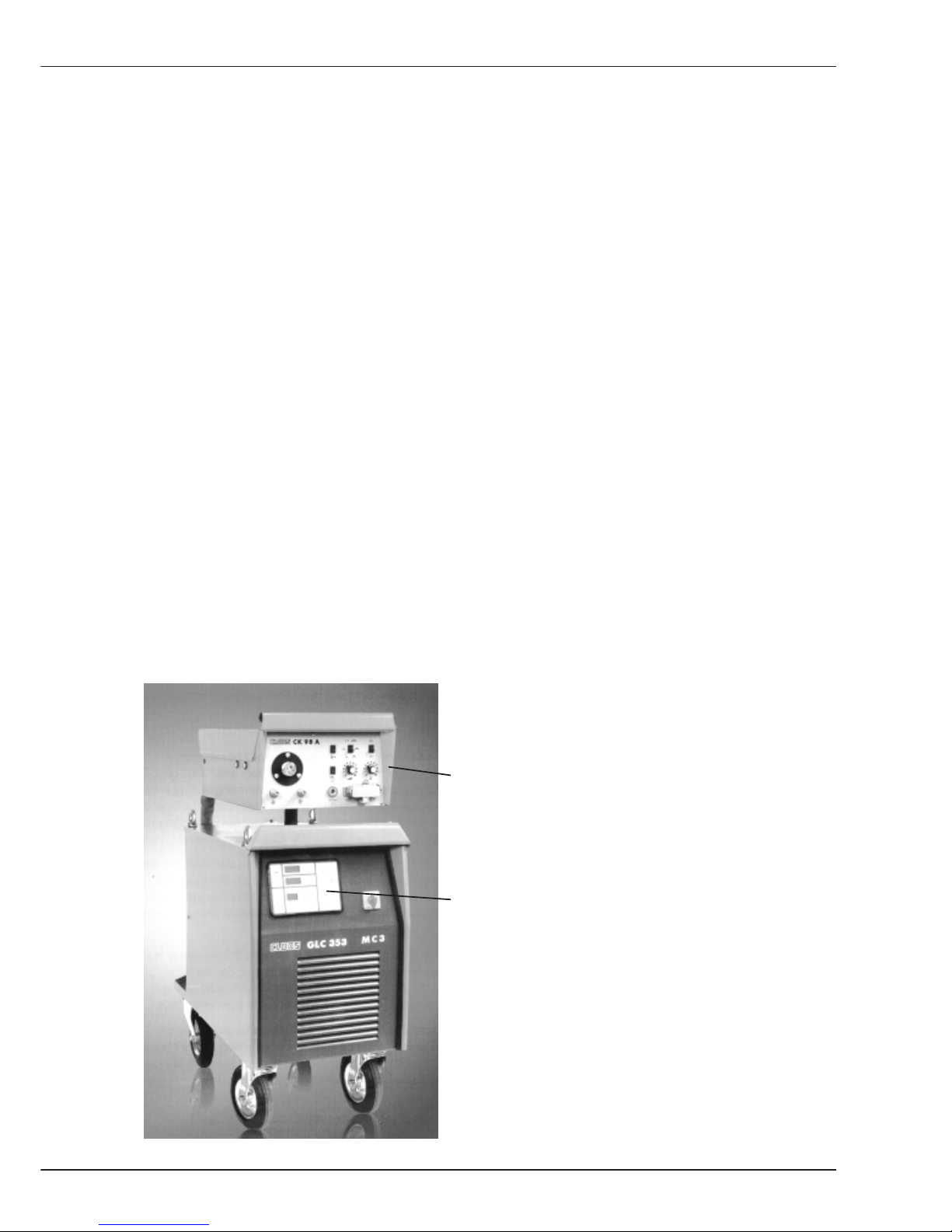
B1 Operating and display elements
The operating and display elements are on the
front plate of the
wire drive unit
and the
power source
B1 Operating and display elements
Page 22
B-4
Operation
GLC 353/503 MC3
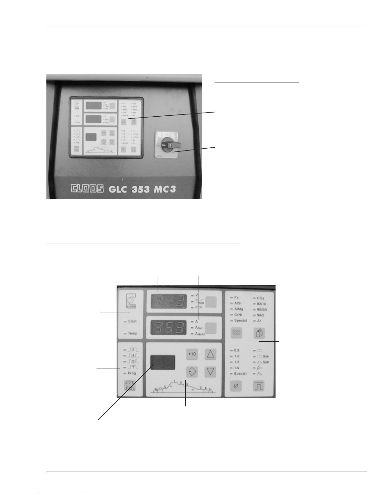
B1.1 Operating and display elements
on the power source
Front view power source
Operating and programming panel
Main switch
The operating and programming panel is subdivided into:
Display 1 Display 2
Operating modes
Signal lamps
Characteristic
curve selection
Programming
B1.1 Operating and display elements Power source
Display 3
Page 23
B-5
Operation
GLC 353/503 MC3
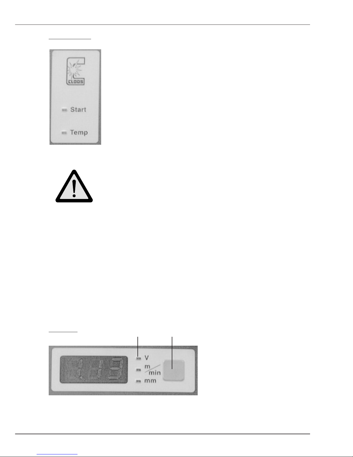
Signal lamps:
The operation panel has two signal lamps:
- Start
- Temp (overtemperature)
Signal lamp Start indicates that the Weld signal was given.
The signal can be given:
- via torch trigger
- externally
- in the operating mode E(lectrode) manual
Caution !
Open circuit voltages exists on connection lugs P and N or on
the welding wire or electrode !
Signal lamp Temperature indicates that the operation temperature of
the following components has been exceeded:
- Welding transformer
- Welding rectifier
- Transistor cascade
- Cooling water pump
- Fan
The welding process cannot be continued if the operating temperature of a component has
been exceeded. Restart is only possible when the overloaded component has cooled
down.
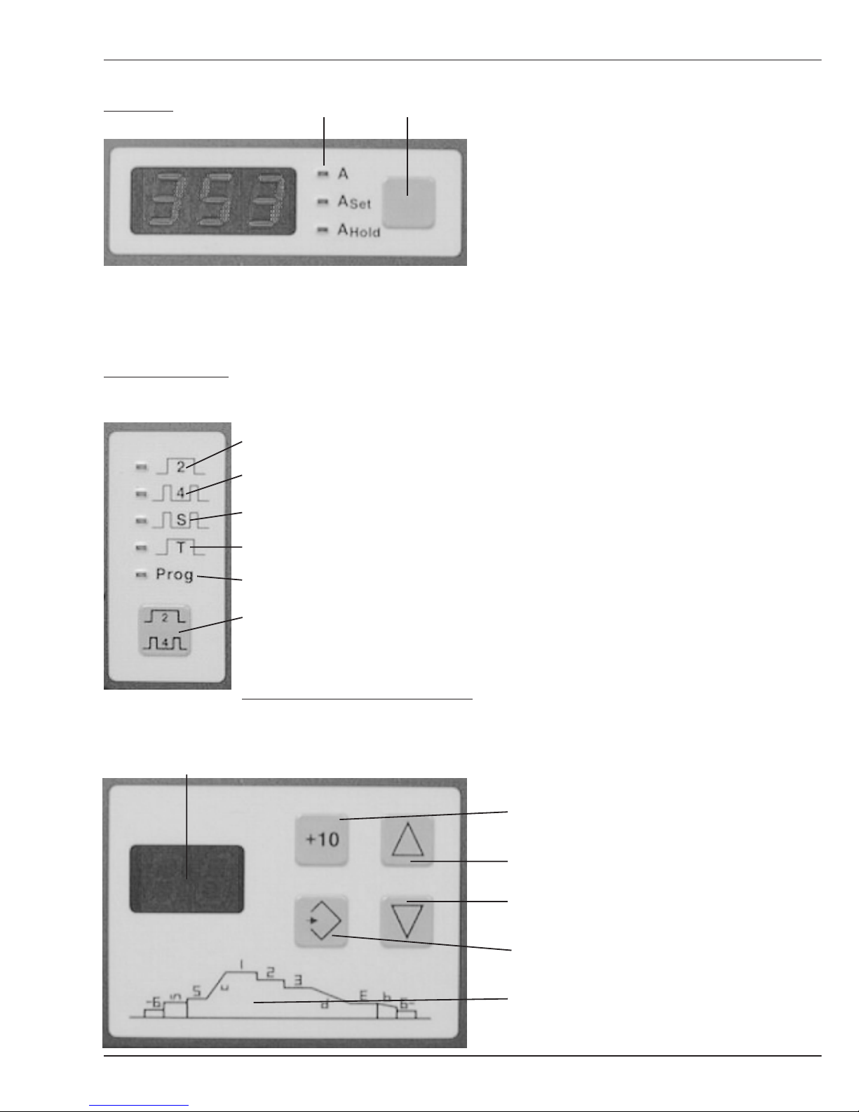
Display 1
The following values are indicated
on the display:
- Welding voltage
- Wire feed speed
- Plate thickness
The value can be selected with the selector key. LED's show the values selected.
LEDs Selector key
B1.1 Operating and display elements Power source
Page 24
B-6
Operation
GLC 353/503 MC3
Display 2 The following values are shown
on the display:
- Weld current actual value
- Weld current set value
- stored weld current actual
value achieved during last weld
(highest current output)
The value can be selected with the selector key. LEDs show the values selected.
Operation panel:
Press the selector key to select
the required operation mode.
The active operation mode is
displayed by LED.
The operating modes are
described under Definitions.
Press and hold the selector key for
more than a second; the input mode
changes and you can start
programming (see chapter
Programming).
Operation panel programming:
More
information is in the
Display for operating sequence and weld process job No. chapter Programming
Key +10 (change value in
increments of 10)
Key Up
Key Down
Key Store
Diagram for programming
a job sequence
LED's Selector key
B1.1 Operating and display elements Power source
Operating mode 2 cycle
Operating mode 4 cycle
Oper.mode Super 4 cycle
Operating mode spot weld
Operating mode program
Selector key
Page 25

B-7
Operation
GLC 353/503 MC3
Operation panel characteristic curve:
On this panel the values are set, from which the integrated processor selects a
characteristic curve.
Parameter Material Parameter Gas
Steel CO
2
Aluminium/Silicon 82% Ar, 18% CO
2
Aluminium/Magnesium 90% Ar, 5% CO2, 5%O
2
Chrome/Nickel 98% Ar, 2% O
2
Programming according Pure Argon
to customer requirements
Selector key Material Selector key Gas
Parameter Wire Operation mode
Wire diameter 0,8 (0.030) Normal 2 buttons
Wire diameter 1,0 (0.039) Normal synergic
Wire diameter 1,2 (0.045) Pulsed synergic
Wire diameter 1,6 (1/16) TIG (DC) "Scratch
Start"
Programming according Electrode
to customer requirements
Selector key Wire Selector key Mode
More details on the operation modes and procedures are in the sections Welding and
Definition.
B1.1 Operating and display elements Power source
Page 26
B-8
Operation
GLC 353/503 MC3
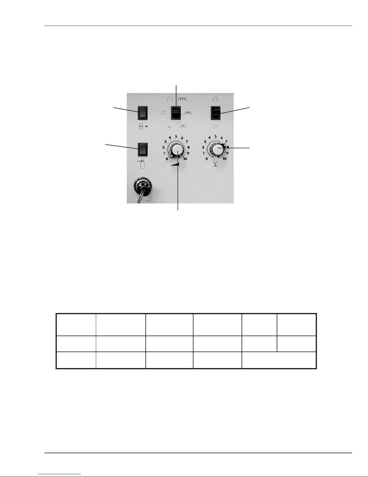
B1.2 Operating elements on the wire drive unit
Switch Pulse adaptation
or choke
Push button Switch With/
Wire manual without pulse
Push button Potentiometer 2
Gas manual Arc length/
(Weld voltage)
Potentiometer 1
Output (wire feed)
During pulse operation the switch 'Pulse adaptation or choke' enables an adaptation of
pulse energy, sometimes required for different cable assembly lengths.
During normal operation this switch 'Pulse adaptation or choke' is used to set the choke
influence.
The table below shows the function of the two Potentiometers, depending on the selected
Procedure.
Procedure Normal Normal Pulse TIG Electrode
2 buttons Synergic Synergic
Poti. 1 Wire feed Output Output Current Current
Poti. 2 Weld voltage Arc length Arc length no function
The Switch without/with pulse is active if the procedure Normal-Synergic or PulseSynergic was selected. You can change over from characteristic curve Normal synergic to
Pulse synergic.
B1.2 Operating elements Wire drive unit
Page 27
B-9
Operation
GLC 353/503 MC3
B1.3 Working modes
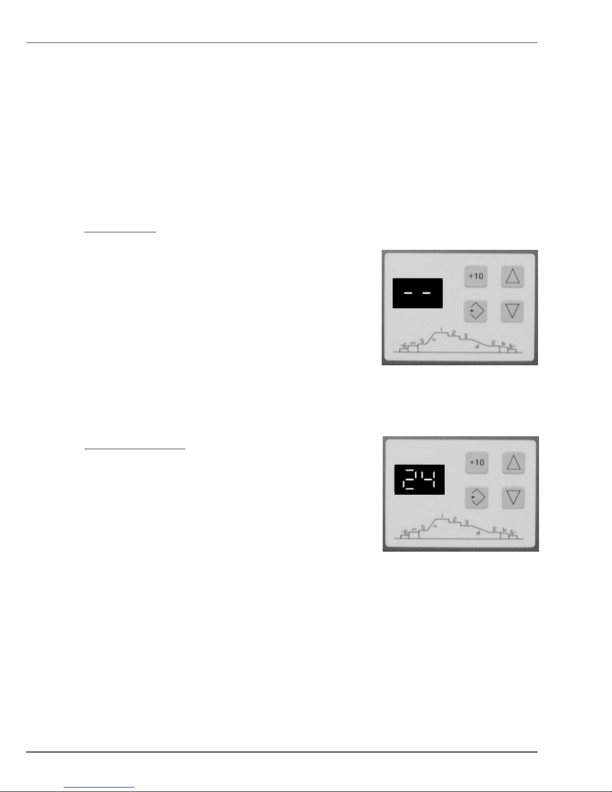
Display 3 indicates the active mode of the weld power source control.
There are two modes:
- Mode Manual
- Mode Programming
Mode Manual:
If two minus characters are shown on display 3, you can
select all values on the power source operation panel
and start welding. On the wire drive unit operation panel
the arc condition is set via potentiometers 1 and 2.
Welding in this mode is described in chapter B2 welding.
Programming Mode:
If a figure between 1 and 50 is shown on display 3, a stored
weld process job is called up.
In this case welding is carried out with programmed
values.
B1.3 Arbeitsmodis
Page 28

B-10
Operation
GLC 353/503 MC3
Page 29
B-11
Welding
GLC 353/503/553 MC3
B2 Welding
B2 Welding
Hereafter please find the operating instructions for the five welding processes.
Please note the following three important instructions:
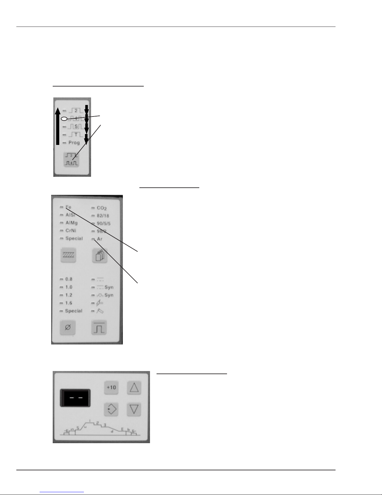
Operation of selector keys:
Example: You want to select the operation mode. The basic setting is
"operation mode 4 cycle" which is indicated by the
LED. By momentarily pressing the
selector key operation mode the next operation mode is switched on etc.
If the last operation mode is indicated and the key is pressed again, the
display jumps back to the first operation mode.
Flashing of LEDs:
The LEDs flash up in accordance with the combination of
selected values on the operation panel characteristic curve
selection.
This flashing signals that there is no characteristic curve
available for this setting. In our example, the values
Steel
and
Argon
have been set. There is no characteristic curve for a
combination of these values because welding is not possible
with this setting.
Select mode manual:
For the following explanations it is required to set the power
source to mode manual.
Please proceed as follows:
When a number appears on display panel 3, press the key
Down until two Minus signs light up.
Mode manual is switched on now.
Page 30
B-12
Welding
GLC 353/503/553 MC3
B2.1 MIG-MAG Normal 2 knob
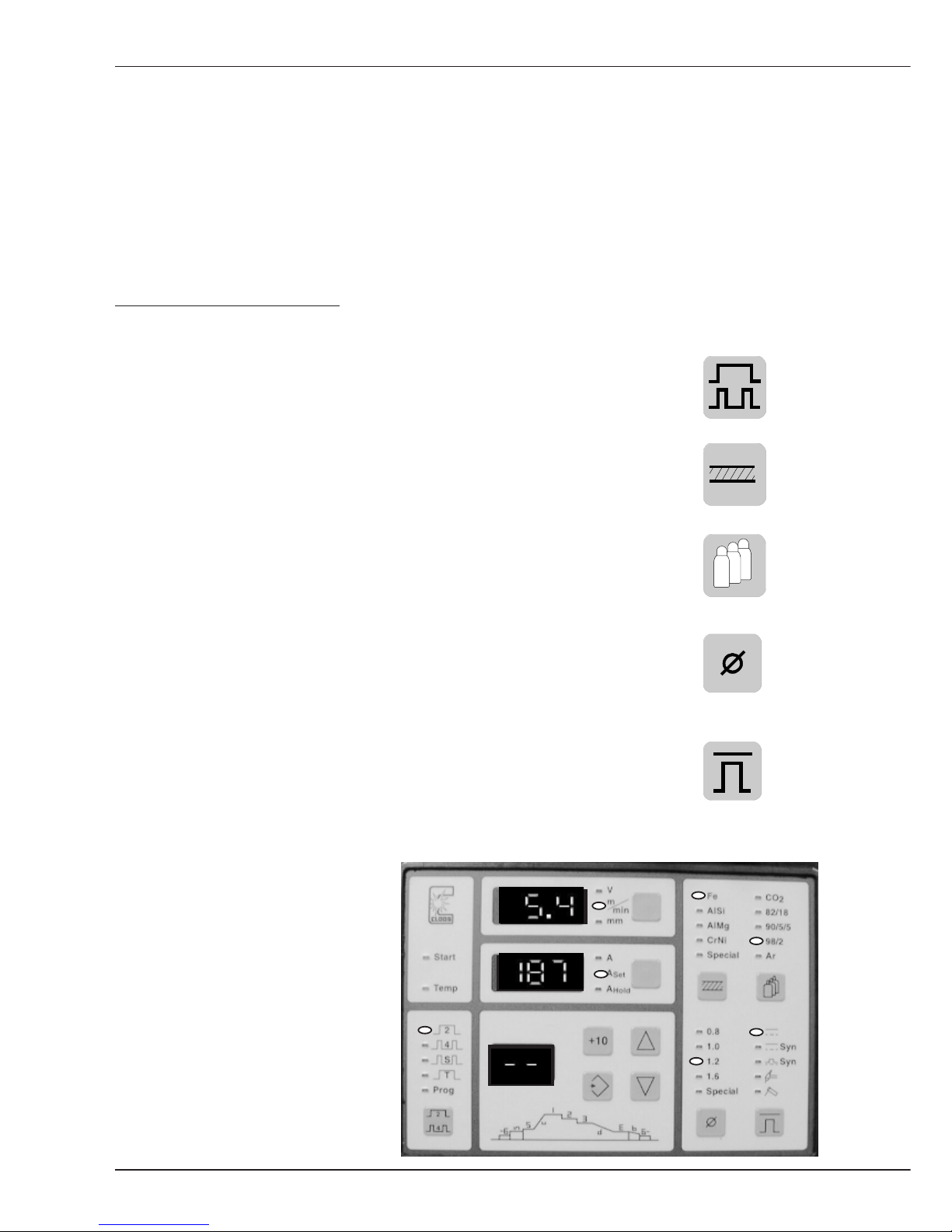
B2.1 Procedure: MIG-MAG Normal 2 knob operation
The following instructions inform you how to use the power source with 2 knob operation,
without internal characteristic curve.
The welder determines the characteristic curve and the working point on the characteristic
curve with the values wire feed speed and weld voltage. After setting the processvalues at
the power source operation panel, the values wire feed and weld voltage are selected at
the wire drive unit operation panel.
Please proceed as follows:
- Switch machine on
- Select the Operating mode by pressing the key.
In our example the operation mode 2 cycle has been set.
- Set the Material to be welded:
In our example Steel is used.
- The Gas used has to be set with the following key:
Mixed gas is used, consisting of 98% Argon and
2% CO2 .
- Set the Wire diameter with the following key:
In the example 1,2 mm diameter welding wire
is used.
- Select the Procedure by pressing the following key:
When welding with 2 knob operation without pulse, the upper
LED flashes (see photo).
- Set the Display 1
by pressing the selector
key until m/min for the wire
feed speed is highlighted.
After setting, the LEDs light up as
shown on the photo.
Page 31
B-13
Welding
GLC 353/503/553 MC3
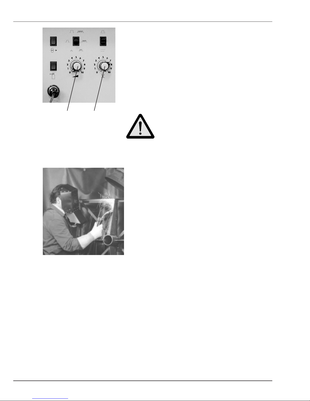
- Select the required Wire feed speed by turning
Potentiometer 1 on the wire drive unit operation panel.
The set value is shown on Display 1 of the power
source.
- Begin welding.
Poti 1 Poti 2 Caution!
Protect eyes and skin against arc
radiation ! Wear protective clothing !
- Turn Potentiometer 2 to adapt the Weld Voltage
to the set wire feed speed.
- Carry out test welds and optimize the settings
on Potentiometer 1 and 2.
- The actual weld parameters voltage and current
are shown on Display 1 - position Volt and on
Display 2 - position Ampere.
Note: If you select A
Hold
on Display 2, the maximum welding current used during
welding can be read at the end of the welding process.
B2.1 MIG-MAG Normal 2 knob
Page 32
B-14
Welding
GLC 353/503/553 MC3
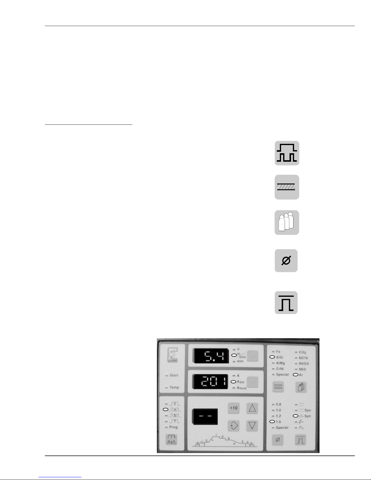
B2.2 MIG-MAG Normal Synergic
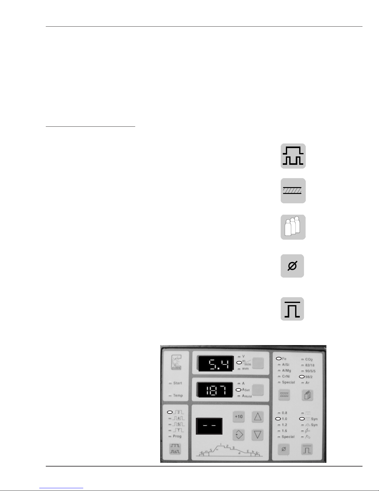
B2.2 Procedure: MIG-MAG Normal Synergic operation
The procedure Normal Synergic can also be designated as single knob operation with
precise setting. The power source processor provides a characteristic curve for any
combination of the values Material, Gas and Wire diameter. Set these values on the power
source operation panel. The characteristic curve working point is selected with the
potentiometer arc output. You are then able to carry out a precise setting with Arc length
potentiometer. The potentiometers are arranged on the operation panel of the wire drive
unit.
Please proceed as follows:
- Switch machine on.
- Select Operating mode by pressing the key:
In our example the operation mode 2 cycle has been selected.
- Set the Material to be welded:
In our example Steel is used.
- The Gas used has to be set with the following key:
Mixed gas is used, consisting of 98% Argon and
2% CO2 .
- Set the Wire diameter with the following key:
In the example wire with a diameter of 1,0 mm is used.
- Select the Procedure by pressing the following key:
When welding with Normal Synergic, the second LED
from the top must light up (see photo).
- Set Display 1 by pressing
the selector key until m/min
for the wire drive speed
appears and Display 2 until
A
Set
for the current set
value appears.
After setting, the LEDs light up as
shown on the photo.
Page 33
B-15
Welding
GLC 353/503/553 MC3
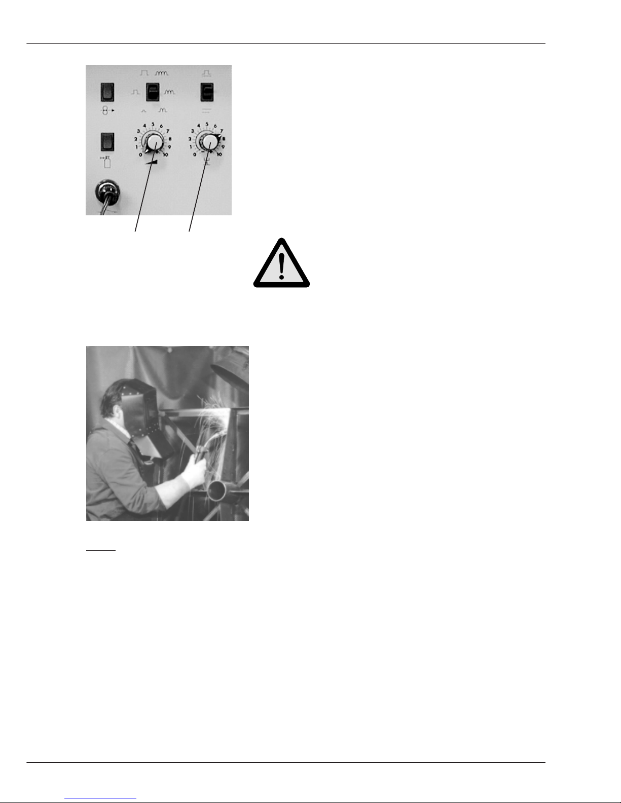
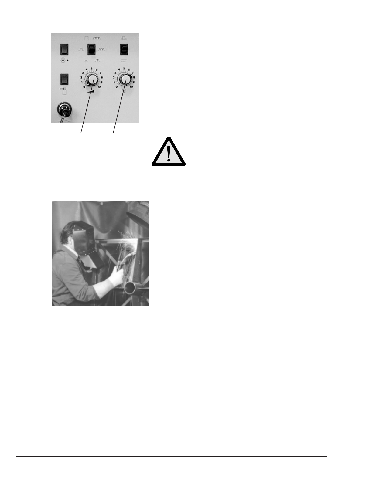
- Select the required Arc output by turning
Potentiometer 1 on the wire drive operation panel.
The resulting values for Wire feed speed and
Welding current set value can be read on
Display 1 and 2 on the power source.
- Begin welding.
Poti 1 Poti 2 Caution!
Protect eyes and skin against arc
radiation! Wear protective clothing !
- Turn Potentiometer 2 to adapt the Arc length to
the set arc output.
- Carry out test welds and optimize the settings on
Potentiometer 1 and 2.
- The actual weld parameters voltage and current are
shown on Display 1 - position Volt and on Display 2
- position Ampere.
Note: Set Display 1 on position mm. The display shows a plate thickness which can
be welded with the set arc capacity. This is only an approximate value which
has to be adapted during production !
If you select A
Hold
on Display 2 the maximum welding current used during
welding can be read at the end of the welding process.
B2.2 MIG-MAG Normal Synergic
Page 34
B-16
Welding
GLC 353/503/553 MC3
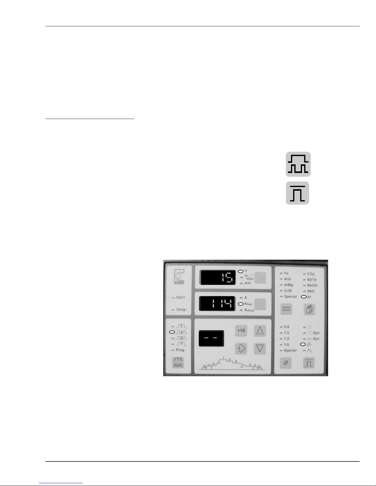
B2.3 Procedure: MIG-MAG Pulse Synergic
The procedure Pulse Synergic can also be designated as single knob operation with
precise setting. The power source processor provides a characteristic curve for any
combination of the vaues Material, Gas and Wire diameter. Set these values on the power
source operation panel. The characteristic curve working point is selected with the
potentiometer arc output. You are then able to carry out a precise setting with the Arc
length potentiometer. The potentiometers are arranged on the operation panel of the wire
drive unit.
Please proceed as follows:
- Switch machine on.
- Select Operating mode by pressig the key:
In our example the operation mode 4 cycle has been selected.
- Set the Material to be welded:
In our example Aluminium/Silicon is used.
- The Gas used has to be set with the following key:
Argon is used here.
- Set the Wire diameter with the following key.
In the example the wire diameter used is 1,6 mm.
- Select the Procedure by pressing the following key:
When weldig with Pulse Synergic, the third LED
from the top must light up (see photo).
- Set Display 1 by pressing
the selector key until m/min
for the wire drive speed
appears and Display 2 until
A
Set
for the current set value
appears.
After setting, the LEDs light up as
shown on the photo.
B2.3 MIG-MAG Pulse Synergic
Page 35
B-17
Welding
GLC 353/503/553 MC3
- Select the required Arc output by turning
Potentiometer 1 on the wire drive operation panel.
The resulting values for Wire feed speed and
Welding current set value can be read on
Display 1 and 2 on the power source.
- Begin welding.
Poti 1 Poti 2 Caution!
Protect eyes and skin against arc
radiation ! Wear protective clothing !
- Turn Potentiometer 2 to adapt the Arc length to
the set wire feed speed.
- Carry out test welds and optimize the settings
by turning Potentiometer 1 and 2.
- The actual weld parameters voltage and current are
shown on Display 1 - position Volt and on Display 2
- position Ampere.
Note: Set Display 1 on position mm. The display shows a plate thickness which
can be welded with the set arc capacity. This is only an approximate value
which has to be adapted during production!
If you select A
Hold
on Display 2 the maximum welding current used during
welding can
be read at the end of the welding process.
B2.3 MIG-MAG Pulse Synergic
Page 36
B-18
Welding
GLC 353/503/553 MC3
B2.4 Procedure: TIG Direct-Current
For TIG Direct-Current Welding you only have to select the operating mode and the
welding current. The arc is ignited by touching the workpiece with the Tungsten electrode.
The Soft-Start function provides lower ignition current and prevents electrode damage
during this procedure. After arc ignition, the welder pulls the welding torch away from the
workpiece and the power source increases the welding current to the set value.
Please proceed as follows:
- Switch machine on.
- Select the Operating mode by pressig the key:
In our example the operation mode 4 cycle has been selected.
- Select the Procedure by pressing the following key:
When welding with TIG Direct-Current, the forth LED from
the top must light up (see photo).
For this welding procedure, it is not required to set the values
Material and Wire diameter.
The value Gas is automatically adopted to the gas type Argon.
- Set Display 2 by pressing
the selector key until A
Set
for the current set value
appears.
After setting, the LEDs light up as
shown on the photo.
B2.4 TIG Direct-Current
Page 37
B-19
Welding
GLC 353/503/553 MC3
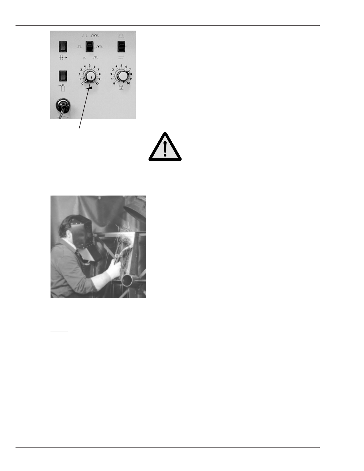
- Select the required Welding current by turning
Potentiometer 1 on the wire drive operation panel.
The set welding current can be read on Display 2
on the power source.
- Begin welding.
Poti 1 Caution!
Protect eyes and skin against arc
radiation! Wear protective clothing !
- Carry out test welds and optimize the setting by
turning Potentiometer 1.
- The actual weld parameters voltage and current are
shown on Display 1 - position Volt and on Display 2 - position Ampere.
Note: If you select A
Hold
on Display 2 the maximum welding current used during
welding can be read at the end of the welding process.
B2.4 TIG Direct-Current
Page 38
B-20
Welding
GLC 353/503/553 MC3
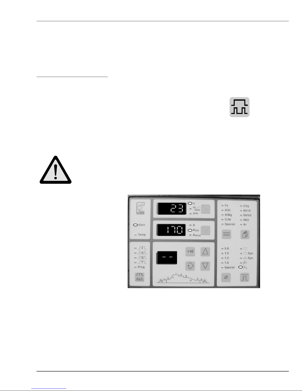
B2.5 Procedure: Coated stick electrodes
The power source provides the operating mode Electrode for welding coated stick
electrodes.
Please proceed as follows:
- Switch machine on
- Select the Operating mode by pressing the following key:
When welding with Electrode the lower LED flashes
(see photo).
During this welding process it is not required to set the values Operating Mode,
Material , Gas and Wire Diameter.
Caution!
Open circuit voltage is available at the connection lugs P and N and
at the stick electrode!
- Set Display 2 by pressing
the selector key until A
Set
appears for the current set
value.
After setting, the LEDs light up as
shown on the photo.
B2.5 Coated Stick Electrodes
Page 39
B-21
Welding
GLC 353/503/553 MC3
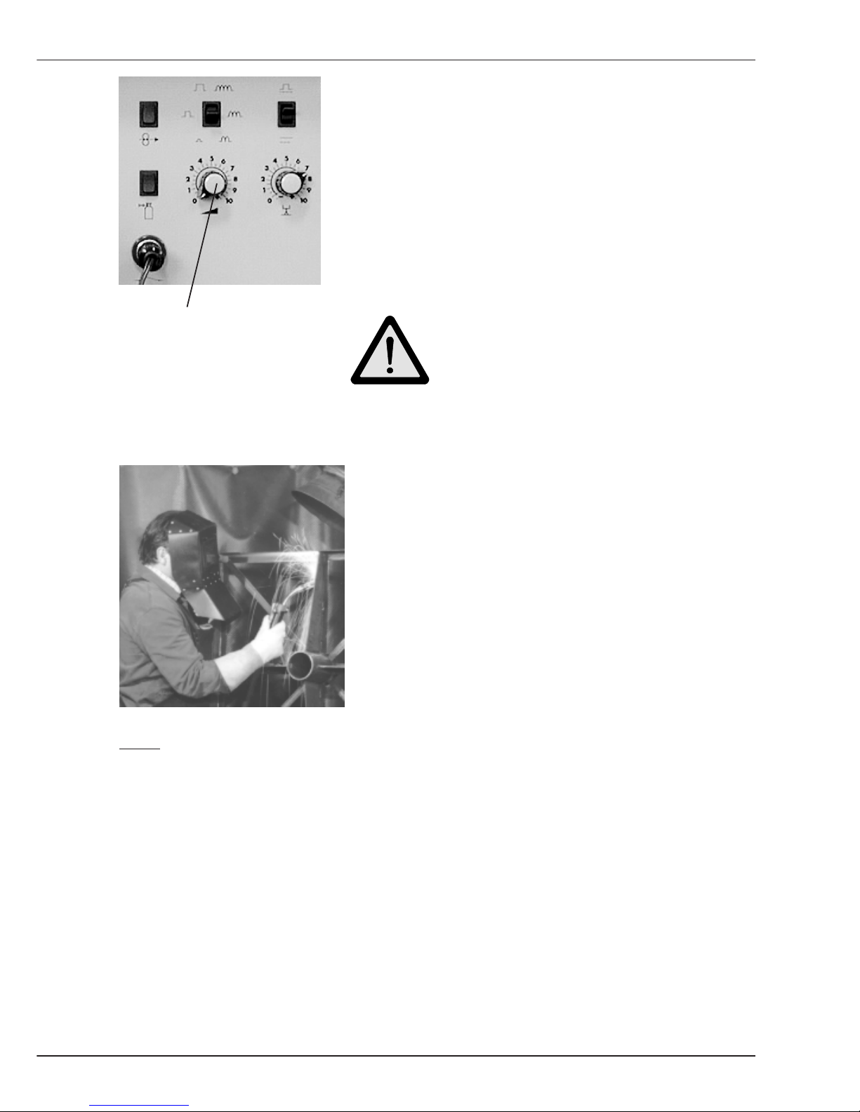
- Select the required Welding current by turning
Potentiometer 1 on the wire drive operation panel.
The set welding current can be read on Display 2
on the power source.
- Begin welding.
Poti 1 Caution!
Protect eyes and skin against arc
radiation! Wear protective clothing !
- Carry out test welds and optimize the setting by
turning Potentiometer 1.
- The actual weld parameters voltage and current are
shown on Display 1 - position Volt and on Display 2 - position Ampere.
Note: If you select A
Hold
on Display 2 the maximum welding current used during
welding can be read at the end of the welding process.
B2.5 Coated Stick Electrodes
Page 40

B-22
Welding
GLC 353/503/553 MC3
Page 41
B-23
Programming
GLC 353/503/553 MC3
P Programming
The welding power source MC3 enables to program and save 50 jobs (weld programs). The
values to be programmed depend on the operating mode used.
Once the welding programs are saved, they can be called up using the job number.
The following values are saved
- Material
- Wire diameter
- Gas
- Procedure
- Wire feed speed or output
- Weld voltage or arc length
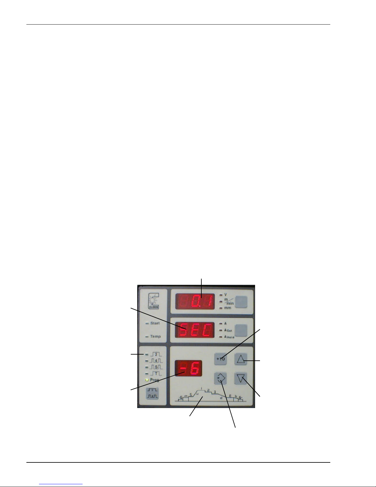
P1 Operating elements for programming
Display 1 shows the actual
vaue
Display 3 shows the
working step and the
weld procedure
sequence numbe
Display 2 shows the actual
value
Operating modes can
be selected
Key Up increases the
actual value
Key Increments of 10
changes the keys Up
and Down in
increments of 10
Key Down reduces the
actual value
Key Save loads the set value
into the memory
Graphic aid for
programming
P1 Bedienelemente für die Programmierung
Page 42
B-24
Programming
GLC 353/503/553 MC3
P2 Program steps
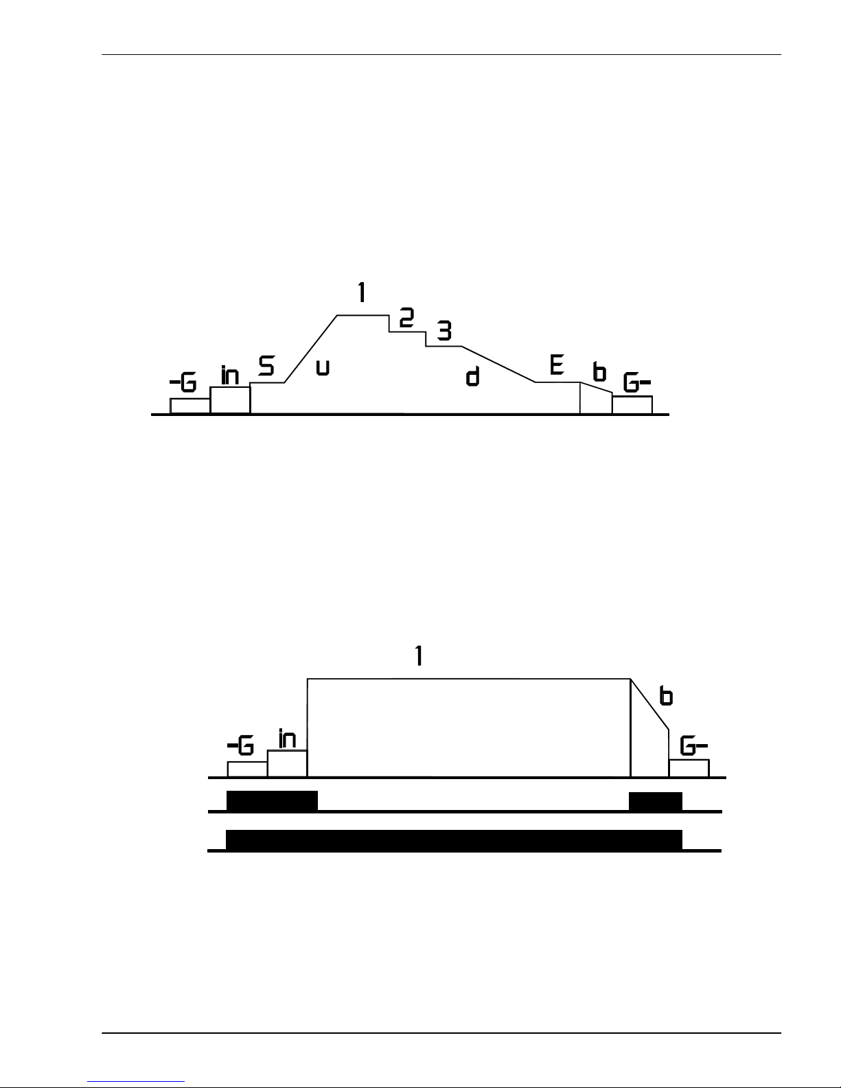
By means of the graphic aid all possible program steps are shown. The abbreviations for the
program steps are shown on display 3. The abbreviations are explained below:
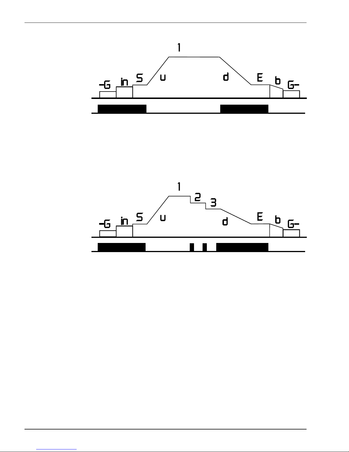
-G Gas preflow 1 Main parameter 1 E End crater program
in Wire "inching-in" speed 2 Main parameter 2 b Burnback
S Start parameter 3 Main parameter 3 G- Gas postflow
u Start ramp (Upslope) d End crater ramp
P3 Operating modes during programming
The number of program steps depends on the operating mode. Actuate the torch trigger to
change to the next program step. The following drawings explain the connection (association)
between operating modes, possible program steps and welding torch trigger.
Operating mode: 2 and 4 cycle:
Program steps
4 cycle
2 cycle
Welding torch trigger
The diagram shows the connection between the program steps and the actuation of the torch
trigger as well as the difference between the operating modes 2 cycle and 4 cycle.
P2 Programmschritte
Page 43
B-25
Programming
GLC 353/503/553 MC3
Operating mode Super 4 cycle:
Program steps
Welding arc active
Squeeze trigger Release trigger Squeeze trigger Release
trigger
Welding torch trigger engagement(s)
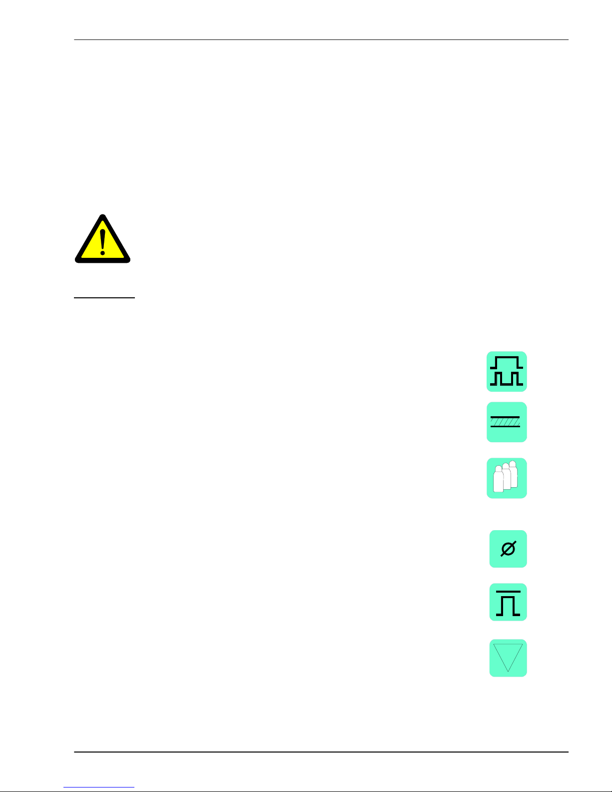
The program steps Start program with start ramp and End crater program with end crater
ramp distinguish the operating modes 2 cycle/4cycle and the operating mode
Super 4 cycle.
Operating mode Prog
Program steps
Welding arc active
Welding torch trigger
In operating mode Prog the program steps Main parameter 2 and Main parameter 3 are
possible. When touching the welding torch trigger you can select between 3 settings. When
pressing the welding torch trigger for < 0,3 seconds only, you remain within the program
steps 1,2,3.
This means if you are in program step 3 and press and release the torch trigger within 0.3
secs, the power sources changes to program step 1. The program step End crater ramp is
started only when pressing the trigger for a longer period.
P3 Betreibsarten beim Programmieren
Page 44
B-26
Programming
GLC 353/503/553 MC3
P4 Programming a weld procedure sequence
The example shows how to program the power source. The number of program steps
depends on the operating mode used (see P3 operating modes during programming).
In our example the operating mode Prog has been selected where all program steps are
possible. If you decide for one of the other operating modes the relevant program steps
cannot be carried out.
In some program steps welding is required to test and adapt the values !
Caution!
Protect eyes and skin against arc radiation!
Wear protective clothing !
Procedure:
- Switch machine on.
- Select the required Operating mode. Actuate the key:
In the example the operating mode Prog has been selected.
- The first setting to be made is the Material:
In the example Steel has been selected.
- The Gas to be used is selected on the following key:
Mixed gas with the components 90 % Argon,
5 % CO2 and 5 % O2 has been selected.
- For setting the Wire diameter use the key:
In the example 1,2 mm wire has been selected.
- Select the Procedure by pressing the key:
Set Pulsed Synergic.
- Press the key Down until the display shows two
minus signs " - - ".
4
2
P4 Programmieren eines Schweißprozessablaufs
Page 45
B-27
Programming
GLC 353/503/553 MC3
When all values have been
set, the operation panel
shows the following:
- Turn Potentiometer 1 and 2 at the
Wire drive unit to mid-position.
- Press the key Operating mode for
more than 1 second.
- The first program step to be made is
setting of Gas preflow.
Actuate the keys Up
or Down until the required
value has been set.
- Press and release the key Operating mode.
The next program step
Wire Inching can be entered.
Actuate the keys Up
or Down until the required
value has been set.
For robotic operation:
The inching-in value is used as
set value, if the command "Wire
by hand" (currentless wire
advance) is given and an external
control voltage is not available.
4
2
4
2
P4 Programmieren eines Schweißprozessablaufs
5
Page 46
B-28
Programming
GLC 353/503/553 MC3
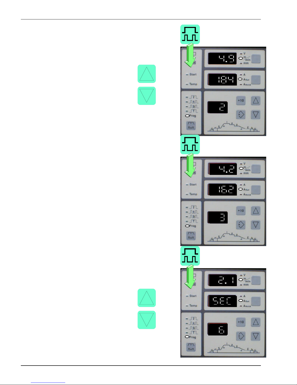
- Press and release the key Operating mode
to enter the value Start capacity.
You can now weld the sizes.
Use the keys Up or
Down until the required arc
has been set. The potentiometers
on the wire drive unit operation
panel can be used for a
precise setting.
- Press and release the key Operating mode.
The Start ramp can be entered.
Actuate the keys Up
or Down until the required
value has been set.
- Press and release the key Operating mode and
enter the Main parameter 1 value.
You can start welding to test and adapt the values.
Use the key Up or
Down until the required arc has
been set. The potentiometers
on the wire drive unit operation
panel can be used for a
precise setting.
4
2
4
2
4
2
P4 Programmieren eines Schweißprozessablaufs
Page 47
B-29
Programming
GLC 353/503/553 MC3
4
2
4
2
4
2
P4 Programmieren eines Schweißprozessablaufs
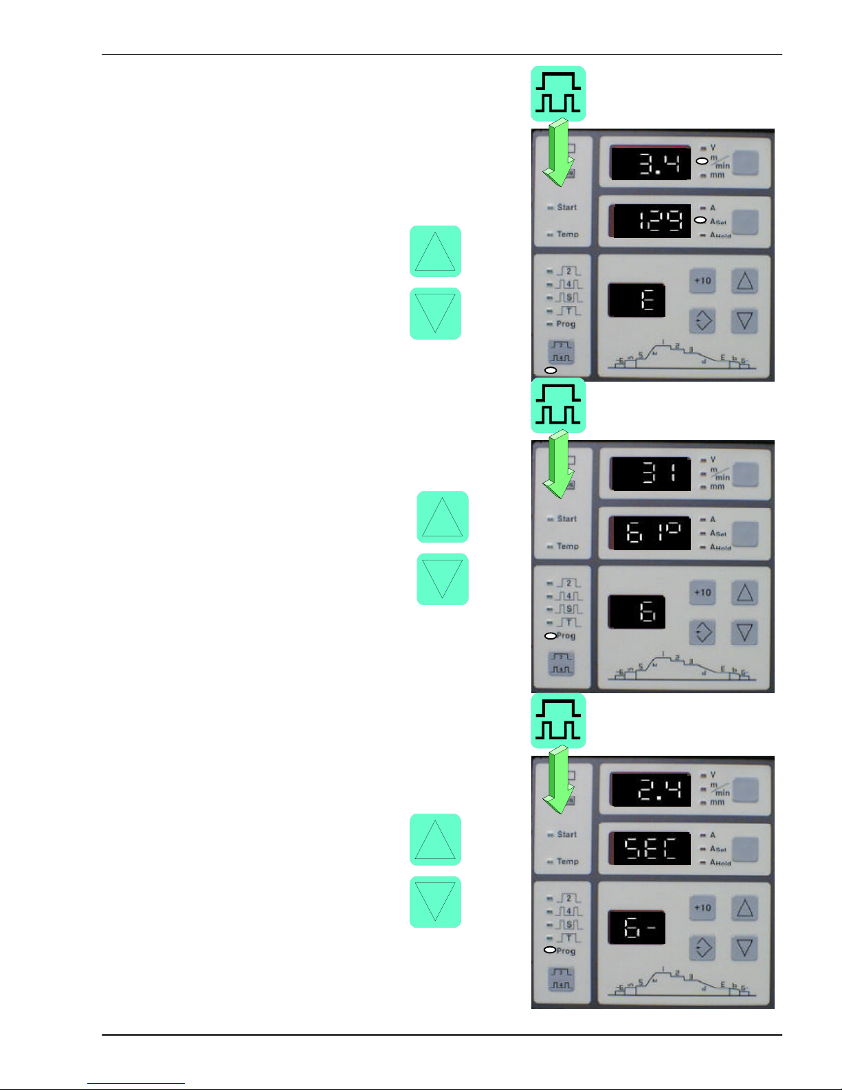
- Press and release the key Operating mode again.
Main parameter 2 can be set.
Proceed in the same way as described for
setting the Capacity 1.
- After setting the Main parameter 2, press the key
Operating mode.
You can now set Main parameter 3.
Please proceed in the same way as described
for setting Main parameter 1 and 2.
If you want to weld with Main parameter 1 and 2 only
you just have to turn the wire feed of
Main parameter 3 to 0.
- Press and release the key Operating mode.
Set the time for End crater ramp.
Actuate the keys Up
or Down until the required
value has been set.
Page 48
B-30
Programming
GLC 353/503/553 MC3
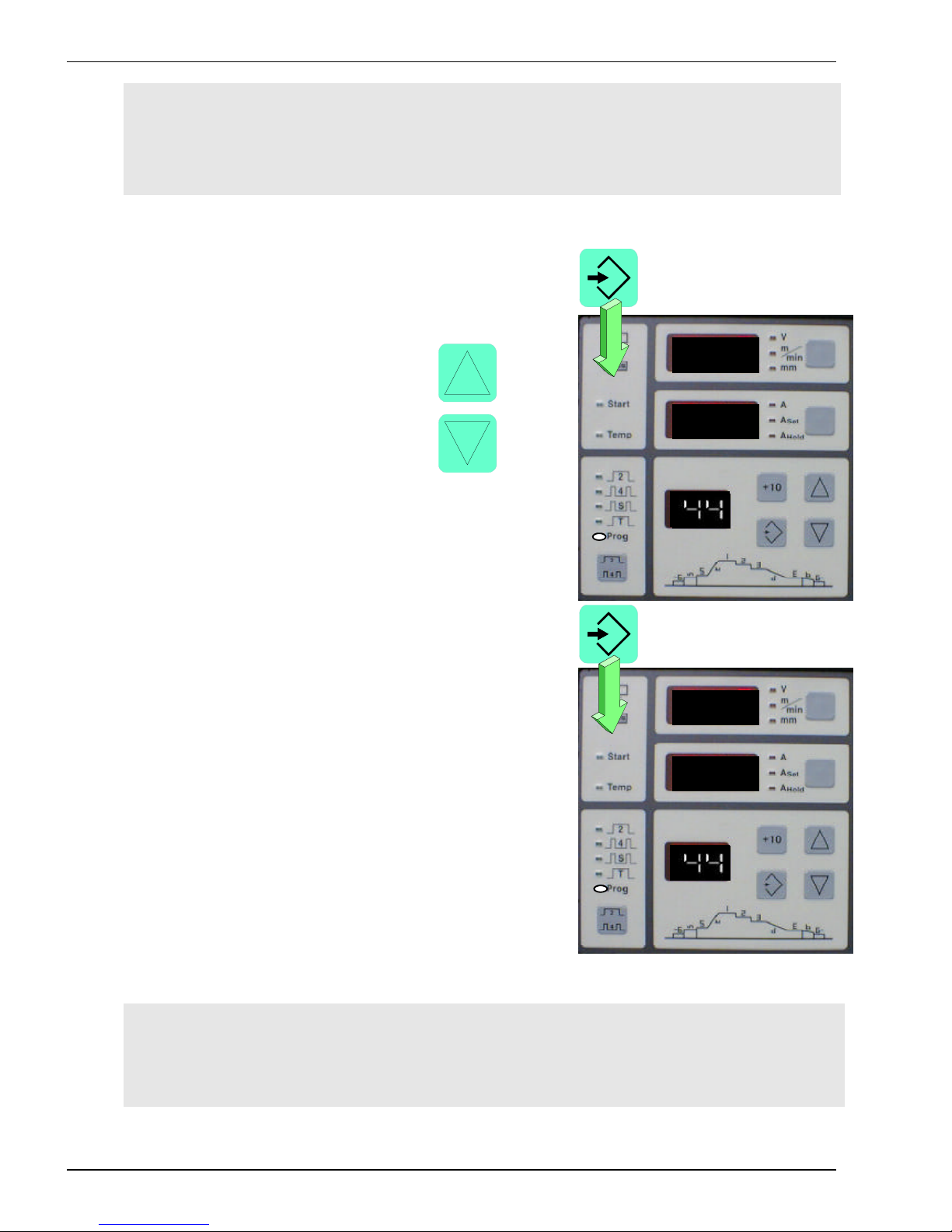
- The next value to be entered is the
End crater parameter. Press the key
Operating mode and set the required
capacity.
Start welding to determine the required
value.
Use the key Up or
Down until the required arc
has been set. The potentiometers
on the wire drive unit operation
panel can be used for precise
setting.
- Press and release the key Operating mode. Enter
the percentage for Wire burn back.
Use the key Up or
Down until the required value
has been set.
- The last value to be programmed is the
Gas postflow. Press and release the key
Operating mode.
Use the key Up or
Down until the required value
has been set.
4
2
4
2
4
2
P4 Programmieren eines Schweißprozessablaufs
Page 49
B-31
Programming
GLC 353/503/553 MC3
P4 Programmieren eines Schweißprozessablaufs
Note: If you press and release the key Operating mode now, the display jumps back
to the value Gas preflow and shows the programmed value. You can modify the
values (using the keys Up and Down ) or jump to the next value by pressing the
Operating mode.
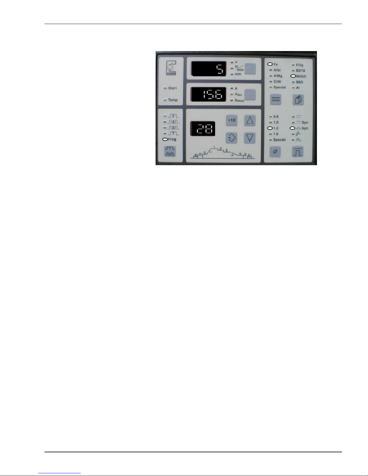
- Press and release the key Save.
The display on Display panel 3 flashes.
Use the keys Up or Down to
select a number between 1 and
50 (in the example 44) to save
the values which have been
programmed.
- Press and hold the key
Save until the display stops
flashing.
You have programmed a weld procedure
sequence under the number 44.
Note: If the values have been saved in mode Manual (two minus signs on display 3),
the programmed values are called up when working without Weld procedure
sequence .
Page 50
B-32
Programming
GLC 353/503/553 MC3
P5 Calling up a weld procedure sequence
Actuate the key Up or
Down until the number of
the required weld procedure
sequence appears on the display.
P6 Correct a weld procedure sequence
Call up a weld procedure sequence. For modifications press the key Operating mode
for approx. 1 second. You may now modify the values as described in chapter P4
Programming a weld procedure sequence.
P5/6 Aufruf & Korrigieren eines Schweißprozessablaufes
Configuration menu
From software V1.56 up it is possible to configure the MC3.
The configuration menu is called up by pressing the key "Wire diameter" for a long time. The
other parameters in the configuration manu are called up by briefly pressing this key.
Use the "Save" key to quit the menu.
The following configuration parameters are available.
From version V1.56 up
· LOC: ( Key switch function )
· GAS: ( Gas flow sensor yes / no )
· ADJ: ( Adjustment range )
Extension from version V1.58 up
· ROL: ( Diameter of rollers )
Extension from version V1.59 up
· DOC: ( Weld data documentation )
Extension from version V1.60 up
· F1: ( Torch function )
Page 51

B-33
Programming
GLC 353/503/553 MC3
Extension from version V1.62 up
· NR: ( Machine number )
Extension from version V1.63 up ( special customers' requirement ) /
series from version V1.64 up
· F2: ( Control voltage control )
· F3: ( Remote controller - configuration )
LOC:
The first parameter to be configured is the function of the key operated switch. The abbreviation
LOC is shown on the current display. The locking position can be set between 0 and 4 using the
arrow keys.
LOC 0 : The storage of jobs is blocked, but all other functions are possible. This
corresponds to the former key switch function and is also used as defaut value.
LOC 1 : In addition to LOC 0 the programming function via operating mode selection key is
also blocked. Consequently, the other parameters such as gas preflow, inching-in
etc. cannot be changed.
LOC 2 : In addition to LOC 1, the characteristic curves cannot be changed via the keys
material, gas, wire diameter and procedure. It is not possible to change over to
other characteristic curves. It is still possible to change the jobs and to set the
operating mode.
The following LOC3 and LOC4 functions are available from software V1.61 up.
LOC 3: This setting allows a change-over from 2 cycle to 4 cycle function; all other
functions of the operation field are blocked.
LOC 4: The complete operation field is blocked with this adjustment.
The restrictions in the operating functions are correspondingly transferred to the remote controller
functions.
DOC:
With this parameter it is possible to document all the relevant process data (seam number,
job number, average current, etc.). However, an additional weld data documentation set is
required for these records.
This documentation must be switched off during PC operation !
ROL:
Three wire drive units are available, which can be selected with this parameter using the
arrow keys.
1. „30“ : (Standard drive, 2+2 rollers, 30mmÆ)
2. „H40“ : (HD drive, 2+2 rollers, 40mmÆ)
3. „E40“ : (HD drive, 2+2 rollers, 40mmÆ, ELVI motor - special!)
GAS:
With the parameter gas sensor, you can change over between "ON" and "OFF", using the
arrow keys. When a gas sensor is available, "ON" must be set.
ADJ:
This parameter enables an adjustment range to be set for each job. The range of values is
between 0 and 100%. The arrow keys are used for setting, for increments of 10 also use the key
„+10“.
Page 52

B-34
Programming
GLC 353/503/553 MC3
In the case of locking via key-operated switch, the capacity (the wire feed speed) can be altered
within the set window.
This window is calculated from the standard value of the job and the set percentage value. The
standard value is defined by saving a job (on the power source or remote controller FB1 or FBB1).
Caling up a job on the power source always activates the standard values. If a job is called up via
FB1 or FBB1, the job with the latest setting is always activated.
If the power source has not been locked via key-operated switch, each parameter can be altered
without restriction (not valid for key-operated torches!).
NR:
With this parameter the machine numbers of the power sources can be configured.
This is required if several power sources are connected to one network.
It is important that all power sources connected have different machine numbers because
otherwise the communication with a PC is not possible. The machine number is set with the
arrow keys.
F1:
When you select F1 (key-operated torch), the arrow keys are used to change over between
"ON and "OFF". When a key-operated torch is connected, "ON" must be active.
During normal operation ( — ), the plus/minus keys on the torch are used to alter the energy in the
complete program range. The last welding value set is saved.
The mid-position of the precise adjustment potentiometer has the value "0". The minimum
value of this potentiometer is „-128“, the maximum value „+128“. When the precise
adjustment is altered, the set value (e.g. +50) is shown in the display panel 2 for approx. 3s.
During job operation - e.g. job 01 - the plus/minus keys on the torch can be used to select another
job in the weld pause.
During welding the same plus/minus keys on the torch can be used to alter the energy. The
adjustment range can be determined with the parameter
ADJ. This requires the installation of a
key-operated switch.
The potentiometer "Power" is inactive in this operating mode.
F2:
This paramter can be configured „ON“ or „OFF“.
The control voltages of both potentiometers P1 and P2 can be checked in the case of an "ON"
configuration.
The set control voltage for the capacity is shown on the display panel 1 of the power source.
The set control voltae for the precise adjustment is shown on the display panel 2 of the power
source.
The parameter automatically returns to "OFF" after each new start of the power source ( machine
off/on switch).
F3:
This parameter can also be configured „ON“ or „OFF“.
„OFF“ When the job is changed via remote controller FB1 or FBB1,
the modified values are maintened.
„ON“ When the job is changed via remote controller FB1 or FBB1,
the originally programmed value is used as setting.
Page 53

B-35
Service and Maintenance
GLC 353/503/553 MC3
S Faults
Faults are divided into three categories:
- Problems during operation
- System fault Overtemperature
- Error messages
Attention
Before any work is carried out inside the power source, the machine
must be switched off and the mains plug disconnected.
After disconnecting the mains plug, wait at least two minutes until the
capacitors in the intermediate circuit have reached safe values!
After maintenance and repair work the side panels and top cover have to be reinstalled.
S1 Problems during operation
Faults which occur when welding can be rectified by qualified personnel or the welder.
Location of electrical faults of repairs must only be carried out by trained service personnel.
If a fault cannot be rectified by your own service staff, please contact your nearest official
CLOOS reresentative.
A list of addresses of Cloos representatives is enclosed (see appendix).
Faults:
- Welding machine cannot be switched on:
1. Check the power lines.
2. Check the T2 transformer. Make sure that it is connected according to the
correct mains voltage.
3. Check the fuses in the welding machine.
S1 Problems during operation
Page 54

Service and Maintenance
B-36
GLC 353/503/553 MC3
- No welding current or very little supplied by machine:
1. Loose contact or arcing at:
- welding current connection lug (P)
- welding current connection lug (N)
- torch connection
- central connection (wire drive unit)
- earth connection
- workpiece clamp (welding ground)
2. Fault in the welding machine
Wire drive unit does not work properly:
1. The wire feed parts (wire drive roller etc.) fitted are for the wrong diameter wire.
2. The wire is bent.
3. The surface is not clean.
4. Counter pressure roller is loose.
5. Wire coil brake is too tight.
6. Tolerance within wire drive is not correct.
Weld seams are porous:
1. Component severely rusted or contaminated by paint/oil or double plate.
2. Distance between welding torch and workpiece is too large.
3. Leaking gas supply.
4. Porosity caused by magnetic blowing action of the welding material. As
preventive measure always keep welding movement away from the workpiece
clamp.
5. Welding torch is held too flat.
6. Gas flow is set too high or too low.
7. Polluted or incorrect gas.
8. Cross wind blows away the shielding gas, i.e. due to open doors or fans.
S1 Problems during operation
Page 55
B-37
Service and Maintenance
GLC 353/503/553 MC3
S2 System fault Overtemperature
The following components are provided with a temperature switch:
- Water cooling pump (motor winding)
- Fan (motor winding)
- Main transformer T1
- Rectifier
- Heat sink in cascade 1 1
- Heat sink in cascade 2 (GLC 503/553 MC3 only)
In the case of overload, the corresponding temperature switch opens.
The arc is switched off and the light diode Temp on the operation panel
of the power source signals the fault.
Cause:
- Pump is overloaded by contaminated cooling agent or blocked
hoses.
- Motor is faulty.
- Permissible duty cycle has been exceeded.
- The cooling air inlet and outlet are covered or contaminated.
- The welding machine interior is severely contaminated.
- The ambient temperature is more than 40° Celsius.
When a flow switch for water cooling (optional) is installed, the LED Temp flashes in the case
of no or unsufficient cooling water flow.
S3 Error messages
CS Test number error
When the message 'CS' appears on display panel 3, this indicates an error in the data memory
of the machine. The PC Software MC3 is required for correction of same. You will find more
details in the PC Software Manual under Diagnosis/Memory administration and Backup.
S2 System fault Overtemperature
Page 56

Service and Maintenance
B-38
GLC 353/503/553 MC3
W Maintenance
W1 Information, intervals
Regular maintenance of the machine is essential for safe and troublefree operation. The
necessary maintenance work and repair work must therefore be carried out at regular
intervals.
This is in any case required by the safety regulations !
The maintenance of the machine mainly concerns the welding torch. The life of the gas
nozzles and current tips, which are subject to wear, can be extended considerably if they
are sprayed from time to time with torch spray, which allows easier removal of weld spatter
or prevents their adhesion altogether.
The liners must be cleaned after welding 50 - 100 kgs wire, depending on wire size. To do
this they are pulled out of the outer hose. The outer hose and the liners are blown out with
dry and clean compressed air.
Attention!
Before any work is carried out inside the power source, the machine must
be switched off and the mains plug disconnected.
After disconnecting the mains plug, wait at least two minutes until the
capacitors have reached safe values!
Daily checks
1. Please check the machine for abnormal vibration, humming noise and smell.
2. Please check the connection lugs, cables, hoses and torch for abnormal heating,
insulation faults, leaks and cleanliness!
3. Please check the coolant level in the container.
4. Please check the wire drive unit. Welding wire abrasion must be removed by using
dry compressed air, which also prevents premature wear.
The mechanical drive parts must be cleaned and greased at regular intervals.
Do not lubricate the drive rolls; this would cause the wire to slip !
5. Attention! If a filter is mounted at the front of the air entry, it must be cleaned when
dirt collects on its surface. Otherwise the duty cycle of the machine is reduced and
the temperature of the torch coolant is increased to an inadmissible range.
Please use caution!
W1 Maintenance: Information, Intervals
Page 57

B-39
Service and Maintenance
GLC 353/503/553 MC3
Monthly checks
1. Please check the cooling fluid for cleanliness.
2. Please check the cooling radiator at the rear of the machine for cleanliness.
Quarterly checks
The water cooling pump is provided with a filter which must be checked and, if necessary, cleaned
after 250 working hours. To do this, the welding machine must be switched off and opened and
the filteron the pump removed. The filter is located at the bottom of the pump body below a cap
nut. It should be cleaned using running water, otherwise the welding torch may be damaged due
to overheating !
Bi-annual checks
1. Please check the interior of the machine and the components for dust and dirt.
2. Please check the mains cable and welding cable for a firm seat and good contact.
3. Please ensure that the machine is always correctly connected to earth (grounded).
4. Please check that the machine cover is correctly assembled and fits tightly.
5. Please check the cooling radiator for bent laminas and re-aligh, if necessary.
W2 Special instructions
W2.1 Dust and dirt
W2.1.1 The cooling efficiency of the radiator, item 88 at the rear, largely depends on
the cleanliness of the laminas. These have to be cleaned at regular intervals.
It is recommended that cleaning is carried out by blowing dry, oil-free
compressed air through the radiator. This will remove any dust and the radiator
will regain its original cooling efficiency.
W2.1.2 Dust and dirt on the main transformer, rectifier, etc. affect the cooling efficiency
of the fan. Metal dust on the main transformer may also lead to insulation
problems and cause earth or winding short circuits. Depending on the degree of
contamination these parts must be vacuum cleaned, .
We advise you not to use compressed air because this would increase the dust
penetration into the components!
A vacuum cleaner can also be used to clean the upper wiring area. As this area
is sealed, this work is only required at relatively long intervals.
W2.2 Cooling agent, anti-freeze agent, disposal
The coolant must be drained off if it is contaminated (it usually becomes a brownish color).
When it must be disposed of, in accordance to State or local codes.
- It must not enter the main drainage system. -
W2 Special instructions
Page 58

Service and Maintenance
B-40
GLC 353/503/553 MC3
The complete cooling system must then be rinsed with fresh distilled water, re- filling,
circulation with the aid of a pump, draining off as far as possible; if necessary use
compressed air. The new cooling agent can be refilled as described under III. in the
operating instruction manual, paragraph 8: Cooling agent.
Only use
CLOOS cooling agent - Part No. 000 01 01 31
which contains
anti-freeze up to -200C
and also protects against corrosion.
Clean cooling agent prevents erosion of the torch body and other parts of
the cooling water system due to electrolytic effect !
W2 Special instructions
Page 59

B-41
Options
GLC 353/503/553 MC3
O Options
The power source GLC 353/503/553 MC3 can be equipped with the following options:
- Key-operated switch
- Serial interface
- Remote controller - connected at CK 98 A -
- Automation interface
These options are described below.
O1 Key-operated switch
The installation of a key-operated switch enables to protect the memory contents of
welding procedures against modifications.
This means : It is impossible to save modifications.
O2 Serial interface
The serial interface enables to connect the power source to a PC or laptop, where the
PC-Software MC3 program developed by Cloos is installed. This option enables the
following functions:
- Save characteristic curves and welding processes in the PC
- Transmit characteristic curves and welding processes to the power source
- Generate characteristic curves
- Print characteristic curve data
O1 Key-operated switch O2 serial interface
Page 60
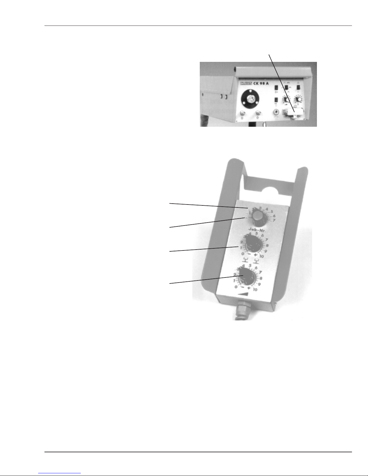
B-42
Options
GLC 353/503/553 MC3
O3 Remote controller
Remote controller connection
The remote controller enables you to change
values when welding takes place far away from
the wire drive unit. The remote controller is
connected at the wire drive operation panel. The
potentiometers 1 and 2 on the wire drive
operation panel are switched off as soon as the
remote controller has been plugged in.
Remote controller operation panel:
Call up the welding processes 1 to 7.
Change over from mode manual to
mode programming.
Potentiometer 2.1: Welding voltage
Arc length
Potentiometer 1.1: Wire feed speed
output
O3 Remote controller
Page 61

B-43
Options
GLC 353/503/553 MC3
O4 Automation interface
An automation interface is used if a coupling between the power source and external controls
(i.e. PLC control) is required. The following external signals can be received via automation
interface:
- Selection of a welding process
- analogue inputs for control of wire feed speed/capacity and voltage/arc length
- digital input for continuation of capacity 1, 2, 3 in operation mode Prog
- digital input for external Start and external Gas
The signals
- arc present
- collective fault
will be sent to external controls.
Accessories coding according to the following list is required!
Resistance values for coding of accessories (remote controller etc) to GLC 353/503/553 MC3.
For coding accessories to the power source a resistor must be instelled between +10V and the
inputs X7/C4 (remote controller socket on wire drive unit) or X15/B7 (peripheral socket).
In the case of the MC3/R a bridge is required beween X15/28 and X15/31.
It is recommended that the resistor is installed in the plug of the remote controller or the
connection cable of a higher voltage control so that the coding is only applicable if the relevant
unit is connected to the power source.
CAUTION ! If a remote controller and a higher voltage control (e.g. a robot) are simultaneously
connected, coding is only allowed on one of the two plugs.
Coding is carried out in steps of 1 Volt, the resistor to be installed represents the upper arm of
a voltage divider. The lower voltage divider is already provided in the control.
The following resistance values are used to set the corresponding voltage level:
8,2 k Ohm 1V Remote controller 038 05 01 00 connected to CK
3,6 k Ohm 2V
2,2 k Ohm 3V
1,3 k Ohm 4V
910 Ohm 5V 1.) Change-over to external set values (control voltage 5+6
above X15)
2. ) ST 104 MC3:
The 2nd torch trigger is only used for change-over to CK 2;
welding on with external start.
620 Ohm 6V ST 104 MC3:
The 2nd torch trigger is only used for change-over to CK2;
welding on with external start.
390 Ohm *7V 1.) Change-over to external set values (control voltage 5+6
above X15)
2. ) Wire currentless with torch trigger
220 Ohm 8V
100 Ohm *9V Wire currentless with torch trigger
0 Ohm 10V Robot version
* Version 1.50 and higher
O4 Automation interface
Page 62
B-44
Options
GLC 353/503/553 MC3
Accessories coding forGLC 353/553 MC3, MC3/R
Set values Set values External Wire current- Robot CK change-over
of CK external start less from torch version external
8,2 k 1V x - x - - 3,6 k 2V
2,2 k 3V
1,3 k 4V
910 5V - x x - - x
620 6V x - x - - x
390 *7V - x x x - 220 8V
100 *9V x - x x - 0 10V - x x x x x
* Version 1.50 and higher
Resistor or bridge in
GLC...MC3
Automation socket X15
between A1 (+10V) and B7 (accessories coding)
GLC...MC3/R
Peripheral socket X15
between 31 (+10V) and 28 (accessories coding)
Page 63

L-1
Elektr. und mech. Beschreibung / electr. and mech.
description / description méc. et électr. GLC 353/503/553 MC3
Ersatzteillisten
Spare parts lists
Listes des pièces de rechange
Page 64
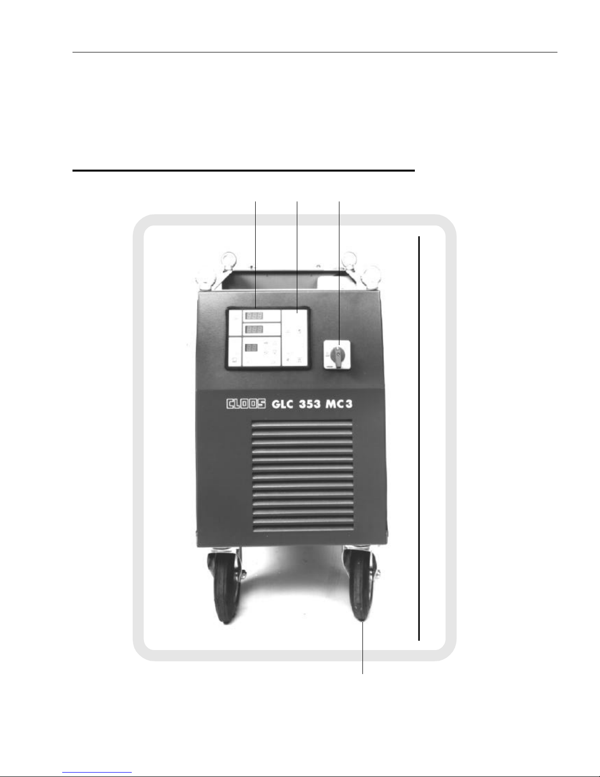
L-2
Elektr. und mech. Beschreibung / electr. and mech.
description / description méc. et électr. GLC 353/503/553 MC3
7. Abbildungen Schweißgerät GLC MC3 /
Illustrations: Welding machine GLC MC3 /
Illustrations: Poste de soudage GLC MC3
57/2
423332
V
Page 65
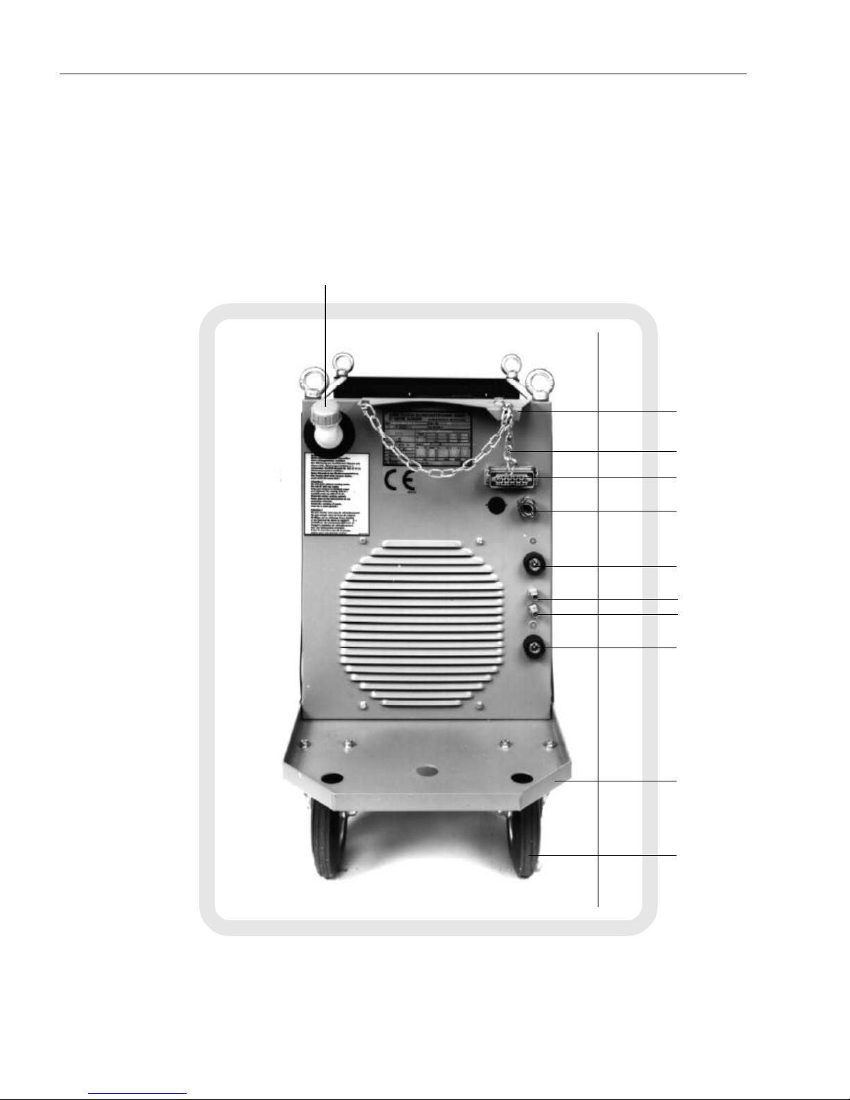
L-3
Elektr. und mech. Beschreibung / electr. and mech.
description / description méc. et électr. GLC 353/503/553 MC3
54
55/1
55/2
51
58
49
50
55
57/1
59/2
59/1
Page 66
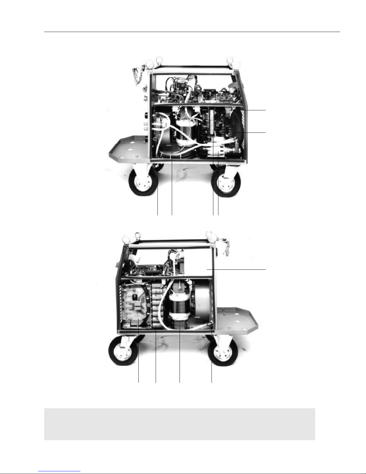
L-4
Elektr. und mech. Beschreibung / electr. and mech.
description / description méc. et électr. GLC 353/503/553 MC3
Abbildung Schweißgerät GLC MC3 /
Illustrations: Welding machine GLC MC3 /
Illustrations: Poste de soudage GLC MC3
45
46
39384060
54
56433447
Page 67
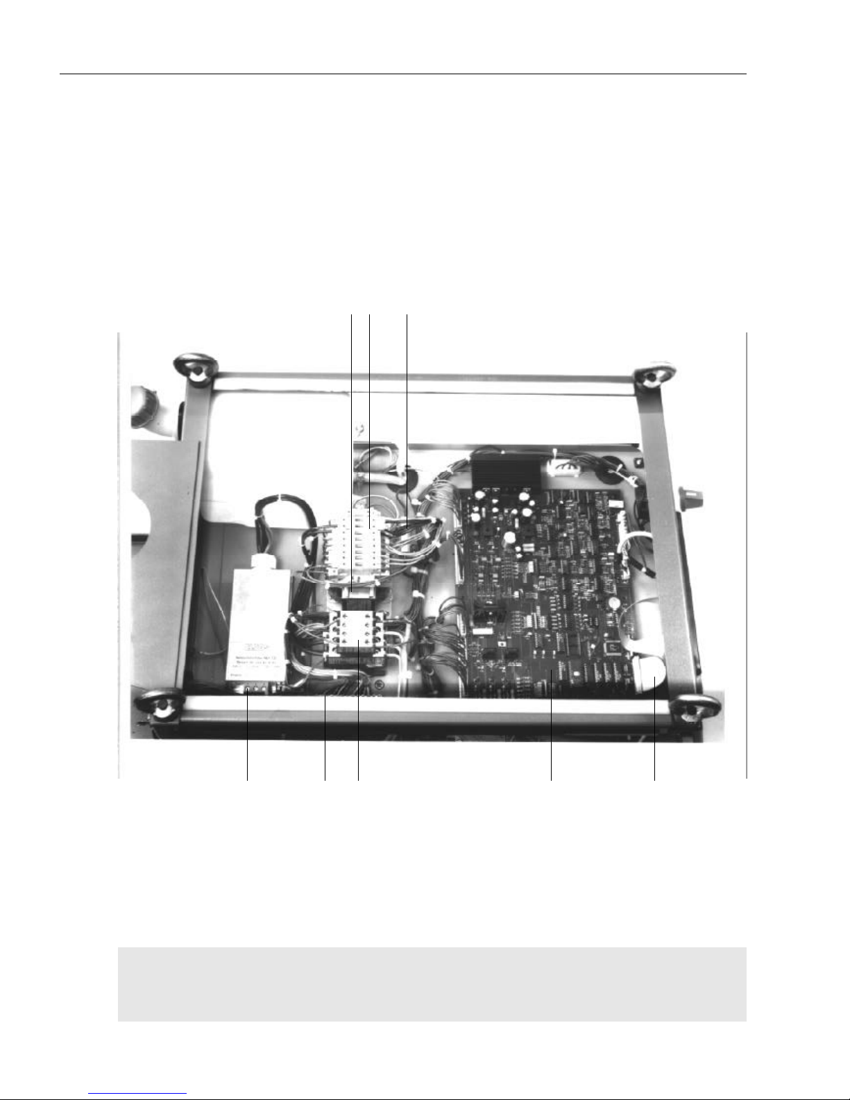
L-5
Elektr. und mech. Beschreibung / electr. and mech.
description / description méc. et électr. GLC 353/503/553 MC3
Abbildung Schweißgerät GLC MC3 /
Illustrations: Welding machine GLC MC3 /
Illustrations: Poste de soudage GLC MC3
53 52 37
31
48
Netzanschluß
35 4144
Page 68
L-6
Elektr. und mech. Beschreibung / electr. and mech.
description / description méc. et électr. GLC 353/503/553 MC3
Ersatzteilliste für GLC 353 MC3, GLC 503 MC3 und GLC 553 MC3 / Spare parts list for GLC 353 MC3,
503 MC3 and 553 MC3 / Liste des pièces de rechange pour GLC 353 MC3, GLC 503 MC3 et GLC 553 MC3
Pos. Bestell-Nr./Ref.-No./ Bezeichnung / Description / Désignation
Référence
A 814 70 00 00 GLC 353 MC3, kpl. Gerät / complete machine / poste complet
B 814 80 00 00 GLC 503 MC3, kpl. Gerät / complete machine / poste complet
C 818 10 00 00 GLC 553 MC3, kpl. Gerät / complete machine / poste complet
31 033 05 55 00 Steuerplatine GLC 353 / control board GLC 353 / platine de commande GLC 353
31 033 05 55 10 SteuerplatineGLC 503 / control board GLC 503 / platine de commande GLC 503
31 033 05 55 20 SteuerplatineGLC 553 / control board GLC 553 / platine de commande GLC 553
32 033 05 57 00 Anzeigeplatine / indicating PCB / platinde d'indication
33 090 01 17 63 Frontplatte kpl. / frot plate compl. / plaque avant cpl.
34 021 01 12 98 Elko für Zwischenkreis 10.000µF/63V - GLC 353 /
Elko for intermediate circuit 10.000µF/63V - GLC 353 /
Elko pour circuit intermédiaire 10.000µF/63V - GLC 353
34 021 01 12 69 Elko für Zwischenkreis 10.000µF/100V - GLC 503/553 /
Elko for intermediate circuit 10.000µF/100V - GLC 503/553 /
Elko pour circuit intermédiaire 10.000µF/100V - GLC 503/553
35 016 02 04 01 Sicherung 4A tr. / slow fuse 4 A / fusible à action retardée 4 A
35 016 02 01 26 Sicherung 0,5A tr. / slow fuse 0,5 A / fusible à action retardée 0,5 A
35 016 02 01 18 Sicherung 1A mT fuse 1A mT / fusible 1A mT
35 016 02 01 29 Sicherung 10A tr. / slow fuse 10 A / fusible à action retardée 10 A
36 016 09 09 00 Option: Durchflußwächter / Option: flow switch / Option: contrôleur de débit
37 012 02 13 50 Schütz Haupttrafo ein, 42V/50...60Hz - GLC 353 /
contactor main transformer on 42V/50...60Hz - GLC 353 /
contacteur transformateur principal marche 42V/50...60Hz - GLC 353
37 012 02 16 00 Schütz Haupttrafo ein, 42V/50...60Hz - GLC 503/553
contactor main transformer on 42V/50...60Hz - GLC 503/553 /
contacteur transformateur principal marche 42V/50...60Hz - GLC 503/553
37 012 02 13 55 Hilfsschalterblock 2S/2Ö / auxiliary switch 2S/2Ö / interrupteur auxiliaire 2S/2Ö
38 802 88 35 00 Schweißstromdrossel / welding current choke / self de courant de soudage
39 023 03 36 00 Pumpe kpl. 230V/50Hz / pump compl. 230V/50Hz / pompe cpl. 230V/50Hz
40 022 04 16 00 Lüfter kpl. 230V/50...60Hz - GLC 353 / fan compl. 230V/50...60Hz - GLC 353 /
ventilateur cpl. 230V/50...60Hz - GLC 353
40 022 04 33 00 Lüfter kpl. 230V/50...60Hz - GLC 503 / fan compl. 230V/50...60Hz - GLC 503 /
ventilateur cpl. 230V/50...60Hz - GLC 503
40 022 04 35 00 Lüfter kpl. 230V/50...60Hz - GLC 553 / fan compl. 230V/50...60Hz - GLC 553 /
ventilateur cpl. 230V/50...60Hz - GLC 553
41 030 04 01 96 Widerstand 1Ohm/50W / resistance 1Ohm/50W / résistance 1Ohm/50W
42 003 22 35 00 Schalter Maschine ein-aus / machine on-off switch /
interrupteur machine marche - arrêt
43 814 23 00 00 Haupttrafo 230/400V - GLC 353 / main transformer 230/400 V - GLC 353 /
transformateur principal 230/400 V - GLC 353
43 813 23 00 00 Haupttrafo 230/400V - GLC 503/553 / main transformer 230/400 V - GLC 503/
553 / transformateur principal 230/400 V - GLC 503/553
44 027 05 25 00 Steuertrafo 230/400V - 218VA / control transformer 230/400V - 218VA /
transformateur de commande 230/400V - 218VA
45 028 09 03 04 Stromsensor / current sensor / détecteur de courant
46 055 08 17 00 Hauptgleichrichter - GLC 353 / main rectifier - GLC 353 /
redresseur principal - GLC 353
46 055 13 02 10 Hauptgleichrichter - GLC 503/553 / main rectifier - GLC 503/553 /
redresseur principal - GLC 503/553
47 055 51 00 00 Transistorkaskade kpl. mit Kondensatorbatterie, Treiberkarte,
Hauptgleichrichter - GLC 353 /
transistor cascade compl. with capacitor battery, driver card,
main rectifier - GLC 353 /
cascade transistor cpl. avec batterie condensateur, carte d'attaque,
redresseur principal - GLC 353
Page 69

L-7
Elektr. und mech. Beschreibung / electr. and mech.
description / description méc. et électr. GLC 353/503/553 MC3
Ersatzteilliste für GLC 353 MC3, GLC 503 MC3 und GLC 553 MC3 / Spare parts list for GLC 353 MC3,
503 MC3 and 553 MC3 / Liste des pièces de rechange pour GLC 353 MC3, GLC 503 MC3 et GLC 553 MC3
Pos. Bestell-Nr./Ref.-No./ Bezeichnung / Description / Désignation
Référence
47 055 45 10 00 Transistorkaskade kpl. mit Kondensatorbatterie, Treiberkarten - GLC 503/553
transistor cascade compl. with capacitor battery, driver card - GLC 503/553
cascade transistor cpl. avec batterie condensateur, carte d'attaque - GLC 503/553
48 038 13 11 00 34 adr. Flachbandkabel / flat cable, 34 leads / câble plat à 34 conducteurs
49 073 03 12 00 Schweißstrombuchse Plus kpl. / welding current bush positive compl. /
. douille du courant de soudage positive, cpl.
50 073 03 12 00 Schweißstrombuchse Minus kpl. / welding current bush negative compl. /
douille du courant de soudage négative cpl.
51 010 09 10 01 25pol. Steuersteckdose f. Koffer, Anbaugehäuse / 25 pole control socket for CK,
housing / prise de commande à 25 pôles pour dévidoir, embase
51 010 09 18 12 25pol. Buchsenteil / 25 pole bush part / pièce à douille à 25 pôles
52 033 04 84 00 PE-Schiene / PE rail / rail PE
53 033 35 19 00 Netzentstörfilter 500V/3x32A /mains interference suppression filter 500V/3x32A/
filtre antiparasite 500V/3x32A
54 054 10 03 00 Kühlwasserbehälter / cooling water tank / réservoir d'eau de refroidissement
54 054 10 03 02 Deckel für dto./ cover for dito / couvercle pour dito
55 Flaschenhalter, Unterteil - GLC 353 / cylinder support, lower part - GLC 353 /
support bouteille, partie inférieure - GLC 353
55/1 Flaschenhalter, Oberteil - GLC 353 / cylinder support, upper part - GLC 353 /
support bouteille, partie supérieure - GLC 353
55 802 89 08 00 Flaschenhalter, Unterteil - GLC 503/553 / cylinder support, lower part - GLC
503/553 / support bouteille, partie inférieure - GLC 503/553
55/1 844 31 08 00 Flaschenhalter, Oberteil - GLC 503/553 / cylinder support, upper part - GLC
503/553 / support bouteille, partie supérieure - GLC 503/553
55/2 049 08 14 06 Kette für Flaschenhalter / chain for cylinder support / chaîne p. support bouteille
56 054 03 24 10 Kühlradiator - GLC 353 /cooling radiator /radiateur de refroidissement GLC 353
56 054 03 08 00 Kühlradiator - GLC 503 /cooling radiator /radiateur de refroidissement GLC503
56 054 03 27 10 Kühlradiator - GLC 553 /cooling radiator /radiateur de refroidissement GLC553
57/1 049 06 00 08 Bockrolle 200mm Ø / fixed roller 200 mm dia. / galet de fixation dia. 200 mm
57/2 049 06 00 07 Lenkrolle 200mm Ø / guide roller 200 mm dia. / galet guide dia. 200 mm
58 035 03 19 00 Kabelverschraubung Pg 21 für Netzkabel / screwed cable gland Pg21 for mains
cable / presse-étoupe Pg 21 pour câble d'alimentation
58/1 035 03 05 01 Gegenmutter Pg 21 / counter nut Pg 21 / contre-écrou Pg 21
59/1 032 03 00 37 Anschluß Kühlwasser zurück / connection - cooling water backwards /
raccord - eau de refroidissement en retour
59/2 032 03 00 37 Anschluß Kühlwasser vor / connection - cooling water forwards /
raccord - eau de refroidissement en avant
60 054 01 02 02 Entleerungshahn für Kühlwasser / drain cook for cooling water /
robinet de vidange pour eau de refroidissement
61 033 11 48 30 Steuerplatte Lüfter I/II ein in GLC 553 MC3 / control board fan I/II on in GLC
553 MC3/ platine ventilateur I/II marche dans GLC 553 MC3
814 70 05 00 Erstausrüstung für GLC 353 MC3 / standard equipment for GLC 353 MC3/
équipement standard pour GLC 353 MC3
814 80 05 00 Erstausrüstung für GLC 503/553 MC3 / standard equipment for GLC 503/553
MC3/ équipement standard pour GLC 503/553 MC3
080 04 00 00 Reduzierventil mit Skala 20l/min. NW 0,6 / reducing valve with 20 l/min. scale,
NW 0.6 / manodétendeur avec échelle 20 l/min. - NW 0.6
101 91 20 12 Ringmutter M12 / nut M12 / écrou à anneau M12
554 01 04 00 Massekabel 70mm² , 5m lang, kpl. - GLC 353 MC3 /
earth cable 70mm² , 5m long, compl. - GLC 353 MC3 /
câble de masse 70mm² , longueur 5m cpl. - GLC 353 MC3
555 01 03 00 Massekabel 95mm² , 5m lang, kpl. - GLC 503/553 MC3
earth cable 95mm² , 5m long, compl. - GLC 503/553 MC3 /
câble de masse 95mm² , longueur 5m cpl. - GLC 503/553 MC3
085 01 01 02 Werkstückzwinge 600A / workpiece clamp 600A / pince 600A
Page 70
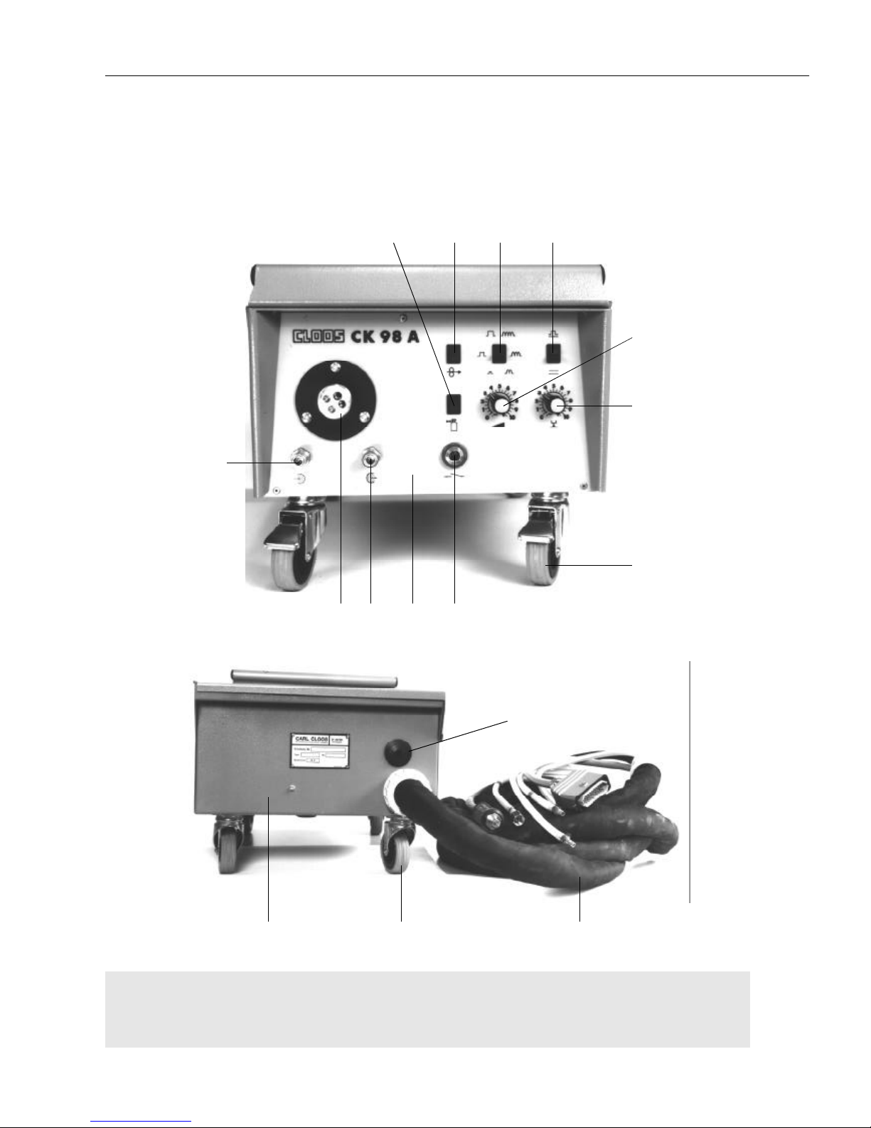
L-8
Elektr. und mech. Beschreibung / electr. and mech.
description / description méc. et électr. GLC 353/503/553 MC3
Abbildungen Drahtantriebsaggregat / Illustrations: Wire drive unit /
Illustrations: Coffret d' entraînement de fil
Drahtantriebsaggregat CK 98 A - Hand
Wire drive unit CK 98 A - manual operation
Coffret d'entraîment de fil CK 98 A - opération manuelle
122 124
130
116
120
13
(110)
119 118 109
123
107
126
106
126
105 102 103 104
Page 71
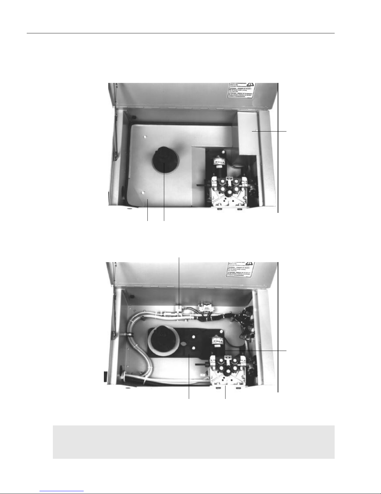
L-9
Elektr. und mech. Beschreibung / electr. and mech.
description / description méc. et électr. GLC 353/503/553 MC3
Drahtantriebsaggregat CK 98 A - Hand
Wire drive unit CK 98 A - manual operation
Coffret d'entraîment de fil CK 98 A - opération manuelle
125 117
101
111
121127
128
Page 72
L-10
Elektr. und mech. Beschreibung / electr. and mech.
description / description méc. et électr. GLC 353/503/553 MC3
Ersatzteilliste für CK 98 A / Spare parts list for CK 98 A / Liste des pièces de rechange pour CK 98 A
A 645 59 01 00 CK 98 A mit 1,0m Schlauchpaket/ CK 98 A with 1,5 m cable assembly /
CK 98 A avec faisceau de câbles de 1,5 m
B 645 59 02 00 CK 98 A mit 5,0m Schlauchpaket/ CK 98 A with 5,0 m cable assembly /
CK 98 A avec faisceau de câbles de 5,0 m
C 645 59 03 00 CK 98 A mit 10,0m Schlauchpaket/ CK 98 A with 10,0 m cable assembly /
CK 98 A avec faisceau de câbles de 10,0 m
101 024 14 29 00 Drahtantriebsmotor 100W mit AC-Tacho/ wire drive motor 100W with AC-tacho/
moteur d'entraînement de fil 100 W avec tachymètre à courant alternatif
102 008 01 00 32 Taste Draht von Hand/ push button wire by hand / bouton poussoir fil à la main
103 008 04 16 00 Umschalter Impuslanpassung/Drossel/ change over switch pulse adaptation/
choke / commutateur adaptation d'impulsions/self
104 008 04 15 00 Umschalter Normal/Puls/ change over normal/pulses /
commutateur soudage normal/impulsions
105 008 01 00 32 Taste Gas von Hand/ push button gas by hand / bouton poussoir gaz à la main
106 030 03 10 01 Potentiometer Leistung 10k lin./ potentiometer capacity 10 k lin./
potentiomètre capacité 10 k lin.
107 030 03 10 01 Potentiometer Spannungsfeinabgleich 10k lin./ potentiometer voltage fine
adustment 10 k lin. / potentiomètre réglage précis de la tension 10 k lin.
109 010 03 03 00 Steckdose Pistole Steuerleitung/ socket torch control lead /
prise ligne pilote de la torche
109 01003 03 02 Isolierring innen/ inner insulation ring / bague isolante intérieure
109 010 03 03 03 Isolierring außen/outer insulation ring / bague isolante extérieure
13 (110) 604 04 06 00 Pistolen-Z-Anschluß/ torch central connection / raccord central de la torche
111 032 02 05 00 Magnetventil für Schutzgas 42V/50...60Hz/ solenoid valve for shielding gas
42V/50...60Hz / électrovanne pour gaz protecteur 42V/50...60Hz
111 048 05 12 20 Magnetventil kpl. mit Drossel NW 0,6 und Gasstauraum/
solenoid valve compl. with choke NW 0,6 and gas retaining tube /
électrovanne cpl. avec self NW 0,6 et tube de retient de gaz
116 035 01 00 37 Gummitülle/ rubber bush / douille en caoutchouc
117 049 01 02 68 Isolierplatte für 2+2-Rollenantrieb/ insulation plate for 2+2 roller drive /
plaque isolante pour
118 090 01 17 65 Frontschild CK 98 A/ front plate CK 98 A / plaque avant CK 98 A
119 032 03 00 37 Anschluß Wasser vor (blau) / connection water forward (blue)/
raccord eau en avant (bleu)
120 032 03 00 37 Anschluß Wasser zurück / connection water return /
raccord eau en retour
121 047 12 00 00 Drahtvorratsrollenhalterung kpl./ wire coil support compl. /
support de la bobine de fil cpl.
122 645 26 10 00 Gehäuse kpl. / housing compl. / embase cpl.
123 049 06 00 11 Feststellrolle vorne/ front fixed roller / galet de fixation avant
124 049 06 00 18 Lenkrolle hinten/ rear guide roller / galet guide arrière
125 645 25 89 11 Grundplatte/ base plate / plaque de base
126 030 03 00 04 Drehknopf/ rotary knob / bouton rotatif
126 030 03 01 04 graue Kappe/ grey cap / capuchon gris
127 645 26 10 20 Abdeckung/ cover / couvercle
128 645 25 98 09 Abdeckung an Frontplatte / cover on front plate / couvercle sur plaque avant
130 650 76 00 60 Schlauchpaket 1,0m lang/ cable assembly 1,0 m long /
faisceau de câbles d'une longueur de 5,0 m
130 650 76 02 00 Schlauchpaket 5,0m lang/ cable assembly 1,0 m long /
faisceau de câbles d'une longueur de 5,0 m
130 650 76 03 00 Schlauchpaket 10,0m lang/ cable assembly 10,0 m long /
faisceau de câbles d'une longueur de 10,0 m
130 650 76 04 00 Schlauchpaket 15,0m lang/ cable assembly 15,0 m long /
faisceau de câbles d'une longueur de 15,0 m
Pos. Bestell-Nr./Ref.-No./ Bezeichnung / Description / Désignation
Référence
Page 73
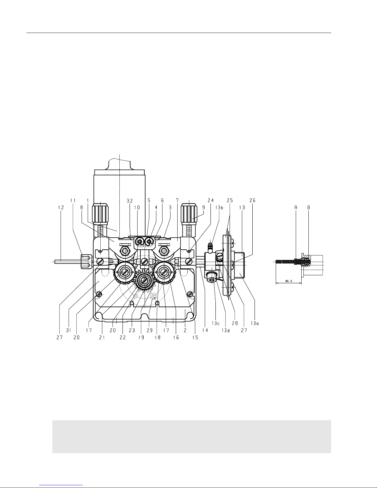
L-11
Elektr. und mech. Beschreibung / electr. and mech.
description / description méc. et électr. GLC 353/503/553 MC3
Schnittzeichnung 2 + 2 Rollen-Drahtantrieb mit Zentralanschluß /
Sectional Crawing: 2 + 2 roller system with central connection /
Vue partielle: Système d´entraînement de fil à 2 + 2 galets avec raccord central
Drahtantrieb kpl Bestell-Nr. 043 46 00 00
Wire drive compl. Order-No. 043 46 00 00 S498
Entraînement de fil compl. Réference 043 46 00 00
Page 74
L-12
Elektr. und mech. Beschreibung / electr. and mech.
description / description méc. et électr. GLC 353/503/553 MC3
Ersatzteilliste 2+2-Rollenantrieb kpl. mit Zentralanschluß für Stahldraht und Röhrchendraht /
Spare parts list 2+2 roller drive compl. with central connection for steel and flux cored wire /
Liste des pièces de rechange pour système à 2+2 galets cpl. avec raccord central pour fil acier et fil fourré
Pos. Bestell-Nr./Ref.-No./ Bezeichnung / Description / Désignation
Référence
043 46 00 00 Drahtantrieb kpl. ohne Motor / wire drive compl. without motor /
entraînement de fil cpl. sans moteur
1 Motor ohne Scheibenfeder und Sicherungsring / motor without curved washer
and Seeger ring / moteur sans rondelle élastique bombée et bague Seeger
2 043 46 00 01 Grundplatte / base plate / plaque de base
3 043 46 00 02 Feder für Druckrollenbügel / spring for pressure roller clip / ressort pour coque
contre-galet
4 043 46 00 03 Paßstift für Druckrollenbügel / set pin for pressure roller clip / goujon pour coque
contre-galet
5 043 46 00 04 Sicherungsring für Druckrollenbügel / Seeger ring for pressure roller clip / bague
Seeger pour coque contre-galet
6 043 46 00 05 Distanzbuchse lang/ distance bush lang / douille d'écartement lang
043 46 00 17 Distanzbuchse kurz (in Verbindung mit Pos. 31) / distance bush kurz (in Verbin-
dung mit Pos. 31) / douille d'écartement kurz (in Verbindung mit Pos. 31)
7 043 46 01 00 Druckrollenbügel rechts kpl. besteht aus / pressure roller clip, right, compl.,
composed of: / coque contre-galet, droite, cpl., se composant de:
043 46 01 01 Druckrollenbügel / pressure roller clip / coque contre-galet
043 46 01 02 Aufnahmebolzen / mounting bolt / boulon de montage
043 46 01 03 Abstandsbuchsen / distance bush / douille d'écartement
043 46 01 04 Gegendruckrolle / counter pressure roller / rouleau de contre pression
043 46 01 05 Mutter M8 / nut M8 / écrou M8
8 043 46 02 00 Druckrollenbügel links kpl. besteht aus - siehe Pos. 7 / pressure roller clip, left,
compl. composed of - see item 7 / coque contre-galet gauche cpl., se
composant de - voir pos. 7
9 043 44 00 19 Druckeinheit kpl. / pressure unit compl. / unité de pression cpl.
10 043 46 00 06 Drahtführungsstück kpl. für Draht Ø 0.8-1.6 / wire guide piece compl. for
wire Ø 0.8 - 1.6 / pièce guide-fil cpl. pour fil Ø 0.8 - 1.6
043 46 00 07 dto. für Draht Ø 1.6-3.2 / dto. for wire Ø 1.6 - 3.2 / dto. pour fil Ø 1.6 - 3.2
11 043 44 00 04 Drahteinlaufstück für Draht Ø 0.8-3.2 / wire inlet piece for wire Ø 0.8 - 3.2 /
pièce d'entrée fil pour fil Ø 0.8 - 3.2
12 043 44 00 14 Drahtführungsspirale für Draht Ø 0.8-1.6 / wire guide spiral for wire Ø 0.8-1.6 /
spirale guide-fil pour fil Ø 0.8 - 1.6
Von der jeweiligen Spirale der Pistole werden ca. 70 mm eingesetzt.
Klemmung durch Konus in Pos.11 / approx. 70 mm of the relevant spiral of the
torch are used. Clamping by cone in item 11 / environ 70 mm de la spirale
correspondante de la torche sont utilisés. Serrage par cône dans pos. 11
13 604 04 06 00 Zentralanschluß kpl. bestehend aus / central connection compl. composed of:/
raccord central cpl., composé de:
13a 604 04 06 01 Zentralanschluß / central connection / raccord central
13b 604 04 06 02 Gasanschlußnippel/ gas connection nipple / nipple raccord gaz
13c 102 20 80 10 Zylinderschraube/ cylinder screw / vis cylindrique
13d 100 70 80 00 U-Scheibe / washer / rondelle
14 043 46 00 11 Verbindungsstück / connection piece / pièce de raccordement
15 043 45 00 08 Drahteinlaufdüse für Draht Ø 0.8 / wire inlet nozzle for wire Ø 0.8 /
tuyère d'entrée fil pour fil Ø 0.8
043 45 00 10 dto. für Draht Ø 1.0 / dto. for wire Ø 1.0 / dto. pour fil Ø 1.0
043 45 00 12 dto. für Draht Ø 1.2 / dto. for wire Ø 1.2 / dto. pour fil Ø 1.2
Page 75
L-13
Elektr. und mech. Beschreibung / electr. and mech.
description / description méc. et électr. GLC 353/503/553 MC3
Pos. Bestell-Nr./Ref.-No./ Bezeichnung / Description / Désignation
Référence
Ersatzteilliste 2+2-Rollenantrieb kpl. mit Zentralanschluß für Stahldraht und Röhrchendraht /
Spare parts list 2+2 roller drive compl. with central connection for steel and flux cored wire /
Liste des pièces de rechange pour système à 2+2 galets cpl. avec raccord central pour fil acier et fil fourré
043 45 00 14 dto. für Draht Ø 1.4 / dto. for wire Ø 1.4 / dto. pour fil Ø 1.4
043 45 00 16 dto. für Draht Ø 1.6 / dto. for wire Ø 1.6 / dto. pour fil Ø 1.6
043 45 00 20 dto. für Draht Ø 2.0 / dto. for wire Ø 2.0 / dto. pour fil Ø 2.0
043 45 00 24 dto. für Draht Ø 2.4 / dto. for wire Ø 2.4 / dto. pour fil Ø 2.4
043 45 00 28 dto. für Draht Ø 2.8 / dto. for wire Ø 2.8 / dto. pour fil Ø 2.8
043 45 00 32 dto. für Draht Ø 3.2 / dto. for wire Ø 3.2 / dto. pour fil Ø 3.2
16 043 46 00 08 Aufnahmebolzen für Zahnrad und Antriebsrolle / mounting bolt for toothed wheel
and drive roller / boulon de fixation pour roue dentée et galet d'entraînement
17 043 46 01 12 Zahnrad für Motor für 2+2 / 4-Rollenantrieb
18 046 03 20 10 Drahtantriebsrolle für Draht Ø 0.8+1.0 / wire drive roller for wire Ø 0.8+1.0 /
galet d'entraînement pour fil Ø 0.8+1.0
046 03 20 12 dto. für Draht Ø 1.0+1.2 / dto. for wire Ø 1.0+1.2 / dto. pour fil Ø 1.0+1.2
046 03 20 14 dto. für Draht Ø 1.4+1.6 / dto. for wire Ø 1.4+1.6 / dto. pour fil Ø 1.4+1.6
046 03 20 16 dto. für Draht Ø 1.2+1.6 / dto. for wire Ø 1.2+1.6 / dto. pour fil Ø 1.2+1.6
Alternativ Antriebsrollen (kalibriert)/ Alternatively Wire drive rollers (calibrated)
Alternative: galets d'entraînement (calibrés)
046 03 26 09 Antriebsrolle für Draht Ø 0,9/ wire drive roller for Ø 0.9 /
galet d'entraînement pour Ø 0,9
046 03 26 10 dto. für Draht Ø 1,0/ dto. for wire Ø 1.0 / dto. pour fil Ø 1.0
046 03 26 12 dto. für Draht Ø 1,2/ dto. for wire Ø 1.2 / dto. pour fil Ø 1.2
046 03 26 13 dto. für Draht Ø 1,32/ dto. for wire Ø 1.32 / dto. pour fil Ø 1.32
046 03 26 16 dto. für Draht Ø 1,6/ dto. for wire Ø 1.6 / dto. pour fil Ø 1.6
Röhrchendraht-Antriebsrollen (gerändelt) / Flux-cored wire drive rollers (knurled)
Galets d'entraînement pour fil fourré (moleté)
046 03 22 16 Antriebsrolle für Draht Ø1,0/1,2R+Ø1,4/1,6R/
wire drive roller for wire / galet d'entraînement pour fil Ø1,0/1,2R+Ø1,4/1,6R
046 03 22 24 dto. für Draht Ø1,4/1,6R+Ø2,0/2,4R/ dto. for wire Ø1,4/1,6R+Ø2,0/2,4R /
dto. pour fil Ø1,4/1,6R+Ø2,0/2,4R
046 03 22 32 dto. für Draht Ø2,8/3,2R / dto. for wire Ø2,8/3,2R / dto. pour fil Ø2,8/3,2R
19043 46 00 09 U-Scheibe / washer / rondelle
20 043 44 00 15 Halteschraube mit Bund M4x6 / fixing screw with collar M4x6 / vis de fixation
avec collet M4x6
21 043 46 01 13 Zahnrad auf Motorwelle / toothed wheel on motor shaft / roue dentée sur l'arbre
du moteur
22 043 17 00 06 Scheibenfeder auf Motorwelle / spring on motor shaft / ressort sur l'arbre du
moteur
23 101 40 00 10 Sicherungsring auf Motorwelle / Seeger ring on motor shaft / bague Seeger sur
l'arbre du moteur
24 043 44 00 18 Paßstift Druckeinheit / set pin pressure unit / goujon unité de pression
25 043 44 00 05 Plastikgehäuse mit Scheibe / plastic housing with disk /
embase en plastique avec rondelle
26 104 81 06 16 Linsenschraube M6 x M16 /oval head screw M6xM16/vis à tête bombée M6xM16
27 100 20 60 12 Zylinderschraube M6x12 / cylinder screw M6x12 / vis cylindrique M6x12
28 100 72 60 00 U-Scheibe A6.4 / washer A6.4 / rondelle A 6.4
29 103 80 60 15 Zylinderschraube M6x15 / cylinder screw M6x15 / vis cylindrique M6x15
Integrierte Spiralenklemmung im Anschlußstück des VSP /
spiral clamping integrated in connection piece of cable assembly /
serrage de spirale intégré dans la pièce de raccordement du faisceau de câbles
A 604 02 22 00 Spannschraube / clamping screw / vis de serrage
B 604 02 23 00 Spanneinsatz für Spirale a Ø 4.0-4.9 / fastening device for spiral, outer Ø 4.0 -
4.9 / dispositif de fixation pour spirale, dia. extérieur 4.0-4.9
Röhrchendrahtausrüstung / equipment for flux cored wire /
équipement pour fil fourré
Page 76
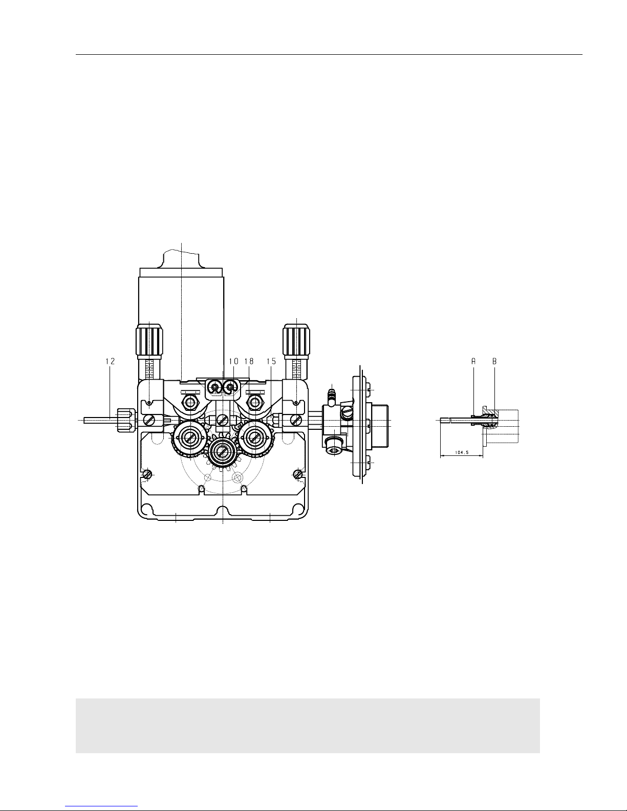
L-14
Elektr. und mech. Beschreibung / electr. and mech.
description / description méc. et électr. GLC 353/503/553 MC3
Aluminiumausrüstung
Aluminium equipment S499
Equipement d´aluminium
Schnittzeichnung 2 + 2 Rollen-Drahtantrieb mit Zentralanschluß /
Sectional Drawing: 2 + 2 roller system with central connection /
Vue partielle: Système d´entraînement de fil à 2 + 2 galets avec raccord central
Page 77
L-15
Elektr. und mech. Beschreibung / electr. and mech.
description / description méc. et électr. GLC 353/503/553 MC3
Pos. Bestell-Nr./Ref.-No./ Bezeichnung / Description / Désignation
Référence
Ersatzteilliste Aluminiumausrüstung für 2+2-Rollenantrieb mit Zentralanschluß /
Spare parts list aluminium equipment for 2+2 roller drive with central connection /
Liste des pièces de rechange pour équipement aluminium pour système à 4 galets, avec raccord central
043 46 10 30 Alu-Ausrüstung kpl. 3.0 m für Draht Ø 1.0 und Ø 1.2 / aluminium equipment
compl. 3.0 m for wire Ø 1.0 and Ø 1.2 / équipement d'aluminium cpl. 3.0 m pour
fil Ø 1.0 et Ø 1.2
043 46 10 40 Alu-Ausrüstung kpl. 4.0 m für Draht Ø 1.0 und Ø 1.2 / aluminium equipment
compl. 4.0 m for wire Ø 1.0 and Ø 1.2 / équipement d'aluminium cpl. 4.0 m pour
fil Ø 1.0 et Ø 1.2
043 46 16 30 Alu-Ausrüstung kpl. 3.0 m für Draht Ø 1.6 / aluminium equipment compl. 3.0 m
for wire Ø 1.6 / équipement d'aluminium cpl. 3.0 m pour fil Ø 1.6
043 46 16 40 Alu-Ausrüstung kpl. 4.0 m für Draht Ø 1.6 / aluminium equipment compl. 4.0 m
for wire Ø 1.6 / équipement d'aluminium cpl. 4.0 m pour fil Ø 1.6
10 043 46 00 14 Drahtführungsstück für Draht Ø 0.8 - Ø 2.0 / wire guide piece for wire Ø 0.8 -
Ø 2.0 / pièce guide-fil pour fil Ø 0.8 - Ø 2.0
043 46 00 15 dto. Ø 2.4 - Ø 3.2 / dto. Ø 2.4 - Ø 3.2 / dto. Ø 2.4 - Ø 3.2
12 Von dem Drahtführungsschlauch der Pistole werden ca.70 mm eingesetzt.
Klemmung durch Konus. / approx. 70 mm of the wire guide hose of the torch
are used / clamping by cone / environ 70 mm du tuyau guide-fil de la torche
sont utilisés / serrage par cône
15 043 45 00 02 Führungsdüse für Drahtführungsschlauch Ø 4.0 / guide nozzle for wire guide
hose outer dia. 4.0 / buse de guidage pour tuyau guide-fil, dia. extérieur 4.0
043 45 00 03 dto. Ø 4.5 / dto. outer dia. 4.5 / dto. dia. extérieur 4.5
043 45 00 04 dto. Ø 5.0 / dto. outer dia. 5.0 / dto. dia. extérieur 5.0
043 45 00 05 dto. Ø 4.7 / dto. outer dia. 4.7 / dto. dia. extérieur 4.7
18 046 03 24 16 Drahtantriebsrolle für Draht Ø 1.0 A, Ø 1.2 A und Ø 1,6 A /
wire drive roller for wire Ø 1.0 A, Ø 1.2 A and Ø 1,6 A /
galet d'entraînement pour fil Ø 1.0 A, Ø 1.2 A et Ø 1,6 A
Alternative Drahtantriebsrollen (kalibriert)/Alternatively Wire drive rollers
(calibrated) Alternative: galets d'entraînement (calibrés)
046 03 27 12 Drahtantriebsrolle für Draht Ø 1,0/Ø1,2A/ wire drive roller for Ø 1.0/Ø1.2A /
galet d'entraînement pour fil Ø 1,0/Ø1,2A
046 03 27 16 dto. für Draht Ø 1,6A / dto. for wire Ø 1.6A / dto. pour fil Ø 1.6A
Integrierte Spiralenklemmung im Anschlußstecker des Pistolen-VSP /
spiral clamping integrated in connection piece of torch cable assembly/
serrage de spirale intégré dans la pièce de raccord du faisceau de câbles de la
torche
A 604 02 22 00 Spannschraube / clamping screw / vis de serrage
B 604 02 23 00 Spanneinsatz für Spirale Ø 4.0-4.9 / clamping device for spiral outer
dia. 4.0-4.9 / dispositif de fixation pour spirale dia. extérieur 4.0-4.9
Page 78
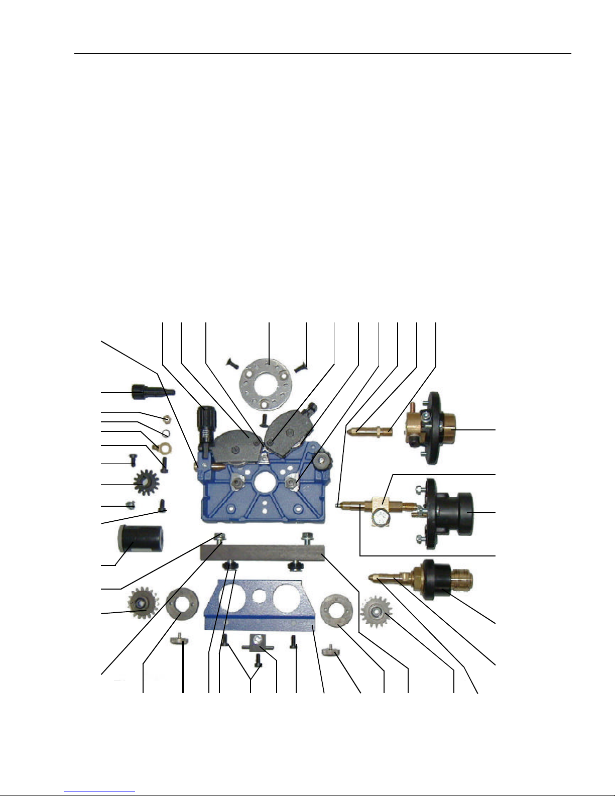
L-16
Elektr. und mech. Beschreibung / electr. and mech.
description / description méc. et électr. GLC 353/503/553 MC3
HD - Antrieb
mit SZ- oder Euro- oder SKQ-Anschluß
HD Drive
with SZ or Euro or SKQ connection
Entraînement HD
avec raccord SZ ou Euro ou SKQ
9 7 3 1+222 23 4 5 33 15 14
13
32
34
35
15624181282525 1017161218
19
6
20
31
25
21
11
25
27
28
30
29
26
26
SZ
Euro
SKQ
37
36
Page 79

L-17
Elektr. und mech. Beschreibung / electr. and mech.
description / description méc. et électr. GLC 353/503/553 MC3
Ersatzteilliste für HD-Antrieb / Spare parts list for HD drive /
Liste des pièces de rechange pour entraînement HD
Pos. Bestell-Nr./Ref.-No./ Bezeichnung / Description / Désignation
Référence
1 043 52 00 02 Aufnahmebolzen für Druckrollenbügel/ mounting bolt for pressure roller clip/
boulon de positionnement pour coque contre-galet
2 043 52 01 02 Linsenschraube mit Bund /oval head screw with collar /
vis à tête bombée avec embase
3 043 52 01 06 Spannfeder rechts / tension spring right / ressort de tension droite
043 52 02 06 Spannfeder links / tension spring left / ressort de tension gauche
4 082 02 02 26 Gegendruckrolle / counterpressure roller / rouleau à contre-pression
5 043 52 00 04 Aufnahmebolzen für Zahnrad / locating bolt for gear wheel /
boulon de positionnement pour roue dentée
6 043 52 00 05 Zahnrad kpl./ gear wheel compl. / roue dentée cpl.
7 043 52 01 00 Druckrollenbügel rechts kpl./pressure roller clip, right, compl. /
coque contre-galet droite cpl.
043 52 02 00 Druckrollenbügel links kpl./ pressure roller clip, left, compl. /
coque contre-galet gauche cpl.
8 043 52 00 11 Abdeckblech / cover plate / plaque de recouvrement
9 043 52 03 00 Druckeinheit kpl./pressure unit compl./ unité de pression cpl.
10 043 52 00 13 Drahtführung für Draht ø0,8-1,2 / wire guide for wire diameter 0.8-1.2 /
guide-fil pour fil diamètre 0,8-1,2
043 52 00 14 Drahtführung für Draht ø1,6-2,0 / wire guide for wire diameter 0.6-2.0 /
guide-fil pour fil diamètre 0,6-2,0
11 043 52 00 06 Zahnrad für Motorwelle / gear wheel for motor shaft /
roue dentée pour l’arbre du moteur
12 043 52 00 07 Befestigungsschraube Rolle / fastening screw for roller /
vis de fixation pour galet
13 043 52 04 00 SZ-Anschluß kpl. (inkl. Pos. 14+15)/ SZ connection compl. (incl. items 14
and 15) / raccord SZ cpl. (y compris les positions 14+15)
604 04 06 50 Grundkörper SZ-Anschluß / basic body SZ connection /
corps de base raccord SZ
14 043 45 00 01 Verbindungsstück / connection part / connecteur
15 043 45 00 08 Drahteinlaufdüse für St-Draht ø0,8/ wire inlet nozzle for steel wire dia. 0.8/
buse d’entrée fil pour fil acier diamètre 0,8
043 45 00 10 dto. für St-Draht/ for steel wire / pour fil acier ø1,0
043 45 00 12 dto. für St-Draht / for steel wire / pour fil acier ø1,2
043 45 00 14 dto. für St-Draht / for steel wire / pour fil acier ø1,4
043 45 00 16 dto. für St-Draht / for steel wire / pour fil acier ø1,6
043 45 00 20 dto. für St-Draht / for steel wire / pour fil acier ø2,0
043 45 00 24 dto. für St-Draht / for steel wire / pour fil acier ø2,4
043 45 00 02 Führungsdüse für Drahtführungsschlauch aø4,0 (Al-Draht)/
guide nozzle for wire guide hose aø4,0 (Aluminium wire)/
buse guide fil pour tuyau guide fil aø4,0 (fil aluminium)
043 45 00 03 dto. für / for / pour aø4,5 (Al-Draht/aluminium wire / fil aluminium)
043 45 00 04 dto. für / for / pour aø5,0 (Al-Draht/aluminium wire / fil aluminium)
043 45 00 05 dto. für / for / pour aø4,7 (Al-Draht/aluminium wire / fil aluminium)
16 049 01 02 69 Isolierbuchse / insulation bush / douille isolante
17 104 12 08 20 Senkschraube M8x20 /countersunk screw M8x20/ vis à tête fraisée M8x20
18 046 03 32 08 Antriebsrolle für St-Draht ø0,8 / drive roller for steel wire dia. 0.8 /
galet d’entraînement pour fil acier diamètre 0,8
046 03 32 09 dto. ø0,9
046 03 32 10 dto. ø1,0
046 03 32 12 dto. ø1,2
Page 80

L-18
Elektr. und mech. Beschreibung / electr. and mech.
description / description méc. et électr. GLC 353/503/553 MC3
Ersatzteilliste für HD-Antrieb / Spare parts list for DR drive /
Liste des pièces de rechange pour entraînement HD
Pos. Bestell-Nr./Ref.-No./ Bezeichnung / Description / Désignation
Référence
046 03 32 13 dto. ø1,14+ø1,32
046 03 32 14 dto. ø1,4
046 03 32 16 dto. ø1,6
046 03 32 20 dto. ø2,0
046 03 32 24 dto. ø2,4
046 03 33 10 Antriebsrolle für Al-Draht ø1,0 / wire drive roller for aluminium wire dia. 1.0/
galet d’entraînement pour fil aluminium diamètre 1,0
046 03 33 12 dto. ø1,2
046 03 33 16 dto. ø1,6
046 03 34 16 Antriebsrolle für Röhrchendraht ø1,0/1,2 + ø1,4/1,6/
wire drive roller for flux cored wire dia. 1,0/1,2 + ø1,4/1,6/
galet d’entraînement pour fil fourré diamètre 1,0/1,2 + ø1,4/1,6/
046 03 34 24 dto. ø2,0+2,4
19 100 70 80 00 U-Scheibe A8,4 / washer A8,4 / rondelle A8,4
20 101 80 80 16 Sechskantschraube M8x16/ hexagon screw M8x16/vis hexagonale M8x16
21 043 46 00 19 Halteschraube mit Bund/safety screw with collar /
vis de blocage avec embase
22 043 52 00 12 Distanzring / distance ring / bague d’écartement
23 104 12 06 16 Senkschraube M6x16 / countersunk screw M6x16 / vis à tête fraisée
24 049 01 03 60 Isolierstück / insulation piece / pièce isolante
25 103 80 60 12 Zylinderschraube M6x12 / cylinder screw M6x12 /
vis à tête cylindrique M6x12
26 043 52 00 08 Drahteinlaufstück für St-Draht ø0,8-1,6 / wire inlet piece for steel wire
ø0,8-1,6 / pièce d’entrée fil pour fil acier ø0,8-1,6
043 44 00 04 dto. für St + Al-Draht ø0,8-3,2 /dito for steel and aluminium wire ø0,8-3,2 /
dito pour fil acier et fil aluminium ø0,8-3,2
048 01 00 15 Anschlußnippel mit Außengewinde R3/8” für St-Draht /
connection nipple with external thread R3/8” for steel wire /
raccord à filetage mâle R3/8” pour fil acier
048 01 00 17 dto. für Al-Draht / dito for aluminium wire / dito pour fil acier
27 103 80 60 15 Zylinderschraube M6x16 / cylinder screw M6x16 /
vis à tête cylindrique M6x16
28 035 02 05 02 Flachstecker / flat plug / fiche plate
29 103 70 60 00 Fächerscheibe A6,4 / washer A6,4 / rondelle A6,4
30 102 80 60 00 Sechskantmutter M6 / hexagon nut M6 / écrou héxagonal M6
31 000 01 01 48 Hochleistungsfett (3cm³)/ heavy duty grease (3cm³) /
graisse à haut rendement (3cm³)
32 604 02 24 00 Euroanschluß kpl. (inkl. Pos. 33+34) / Euro connection compl. (including
items 33+34) / raccord Euro cpl. (y compris les positions 33+34)
33 604 02 24 03 Einsatzrohr für St-Draht iø2,0x10⁵ / insertion tube for steel wire inner
diameter 2.0x10⁵/ tuyau insertion pour fil acier dia. int. 2,0x10⁵
604 02 24 04 dto. iø3,0x10⁵ /dito inner diameter 3.0x10⁵/ dito dia. int. 3,0x10⁵
604 02 24 05 dto.für Al-Draht / for aluminium wire / pour fil aluminium ø2,0x10³
34 604 02 24 02 Verbindungsstück kpl. mit Klemmutter und O-Ring /
connection piece compl. with tightening nut and O-ring /
pièce de raccord cpl. avec écrou de calage et bague O
604 02 25 06 Klemmutter / tightening nut / écrou de calage
604 02 25 07 O-Ring / O-ring / bague O
35 043 52 05 00 SKQ-Anschluß kpl. / SKQ connection compl. / raccord SKQ cpl.
36 043 52 05 01 Verbindungsstück / connection piece compl. / piéce de raccord cpl.
37 604 02 26 03 Stromklemme kpl. / current terminal clamp compl. / griffe d’alimentation cpl.
Page 81
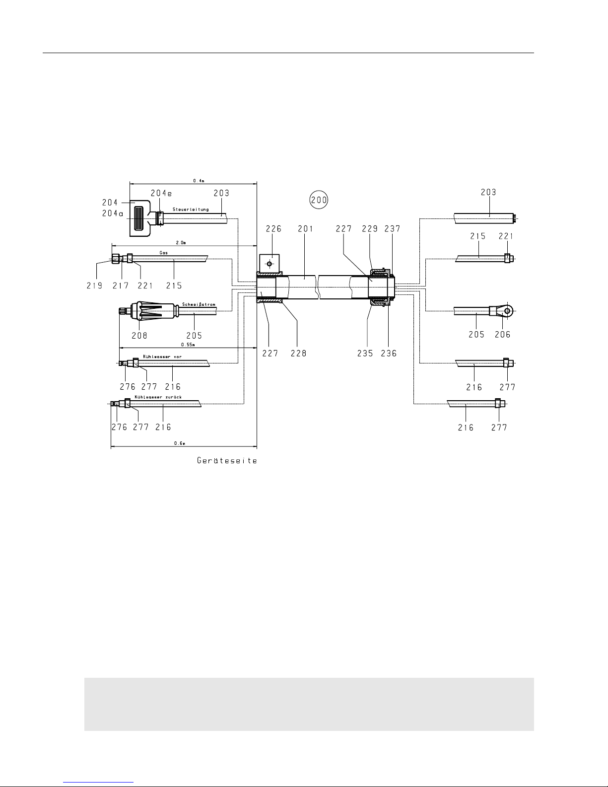
L-19
Elektr. und mech. Beschreibung / electr. and mech.
description / description méc. et électr. GLC 353/503/553 MC3
Schlauchpaket CK 98 A, fest angeschlossen
Cable assembly for CK 98 A, firmly connected / S 534
Faisceau de câbles pour CK 98 A, fixe (non détachable)
Page 82
L-20
Elektr. und mech. Beschreibung / electr. and mech.
description / description méc. et électr. GLC 353/503/553 MC3
Pos. Bestell-Nr./Ref.-No./ Bezeichnung / Description / Désignation
Référence
Schlauchpaket für CK 98 A /
Cable assembly for CK 98 A /
Faisceau de câbles pour CK 98 A
200 650 76 00 60 Schlauchpaket kpl. 1,0 m/ cable assembly compl. 1,0 m /
faisceau de câbles cpl. 1,0 m
650 76 02 00 dto. 5,0m/ dito 5,0 m / dito 5,0 m
650 76 03 00 dto. 10,0m/ dito 10,0 m / dito 10,0 m
650 76 04 00 dto. 15,0m/ dito 15,0 m / dito 15,0 m
201 040 06 09 00 Schutzschlauch Ø45x2 0,6m/ protective hose Ø45x2 0,6m /
tuyau de protection Ø45x2 0,6m
dto. 5,0m/ dito 5,0 m / dito 5,0 m
040 06 23 00 Schutzschlauch Ø50x2 10,0m/ protective hose Ø50x2 10,0m /
tuyau de protection Ø50x2 10,0m
dto. 15,0m/ dito 15,0 m / dito 15,0 m
203 038 06 07 00 Steuerleitung 26x1mm² 2,0m/ control lead 26x1mm² /
câble de commande 26x1mm²
dto. 6,4m/ dito 6,4 m / dito 6,4 m
dto. 11,4m/ dito 11,4 m / dito 11,4 m
dto. 16,4m/ dito 16,4 m / dito 16,4 m
204 010 09 12 02 Tüllengehäuse 25 pol./ 25 pole hood / capot à 25 pôles
204a 010 09 18 13 Stiftteil 25 pol./ 25 pole multiple plug / fiche multiple à 25 pôles
204c 010 09 18 03 Crimpstift 0,75-1,0mm²/ crimp pin 0,75-1,0mm²/ pin 0,75-1,0mm²
204e 035 03 16 01 Klemmschraubnippel Pg 16/ clamped joint Pg 16 / raccord boulonné Pg 16
205 038 03 05 00 Schweißkabel 95mm² 1,75m/ welding cable 95mm² 1,75m /
câble de soudage 95mm² 1,75m
dto. 6,15m/ dito 6,15 m / dito 6,15 m
dto. 11,15m/ dito 11,15 m / dito 11,15 m
dto. 16,15m/ dito 16,15 m / dito 16,15 m
206 035 02 00 94 Kabelschuh 95mm²/ cable lug 95mm²/ cosse de câble 95mm²
208 073 03 11 00 Steckerteil 95mm²/ male connector 95mm²/ connecteur mâle
215 040 04 01 00 Gasschlauch 3,1m/ gas hose 3,1 m / tuyau de gaz 3,1 m
dto. 7,5m/ dito 7,5 m / dito 7,5 m
dto. 12,5m/ dito 12,5 m / dito 12,5 m
dto. 17,5m/ dito 17,5 m / dito 17,5 m
216 040 02 01 00 Wasserschlauch 1,75m/ water hose 1,75 m / tuyau d'eau 1,75 m
dto. 6,15m/ dito 6,15 m / dito 6,15 m
dto. 11,15m/ dito 11,15 m / dito 11,15 m
dto. 16,15m/ dito 16,15 m / dito 16,15 m
217 060 01 00 03 Schlauchtülle klein/ hose busing, small / douille pour tuyau, petite
219 060 04 00 01 ÜberwurfmutterR3/8"/ union nut R 3/8" / écrou chapeau R 3/8"
221 042 02 00 07 Einohrklemme 12.8/ ear clamp 12.8 / borne à une oreille 12.8
226 049 03 02 00 Halteschelle f.Ø45 + Ø50 nicht bei 1,0m VSP/
holding clip for Ø45 + Ø50, not for 1,0 m cable assembly /
bride d'arrêt pour Ø45 + Ø50 / pas pour faisceau de câbles de 1,0 m
227 049 03 02 01 Innenkonus f. Schlauch Ø45/ inner cone for cable Ø 45 /
cône intérieur pour câble Ø 45
049 03 02 04 dto. Ø50 bei 1,0m nur kofferseitig/
228 049 03 02 02 Außenkonus f. Schlauch Ø45/ outer cone for cable Ø 45 /
cône extérieur pour câble Ø 45
049 03 02 05 dto.Ø50 nicht bei1,0m VSP/ dito Ø 50, not for 1,0 m cable assembly /
dito Ø 50, pas pour faisceau de câbles de 1,0 m
229 035 05 05 06 Zugentlastung für VSP/ strain relief gland for cable assembly /
presse-étoupe pour faisceau de câbles
235 035 03 21 02 Überwurfmutter/ union nut / écrou à chapeau
236 035 03 21 01 Einschraubstutzen/ screw socket / manchon fileté
237 035 03 07 01 Gegenmutter Pg 36/ counter nut Pg 36 / écrou isolé Pg 36
276 032 03 00 76 Stecktülle/ plug-in bush / douille enfichable
277 042 02 00 15 Einohrklemme 13,8/ ear clamp 13,8 / pince d'oreille 13,8
Page 83
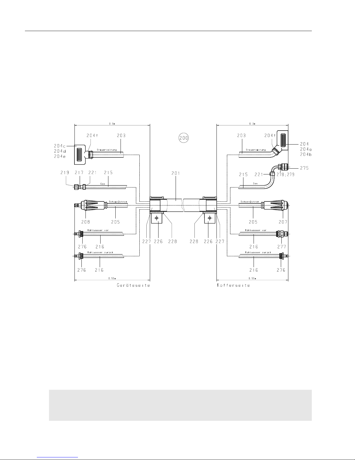
L-21
Elektr. und mech. Beschreibung / electr. and mech.
description / description méc. et électr. GLC 353/503/553 MC3
machine side/côté de la machine side of wire drive unit/côté du dévidoir
Schlauchpaket wassergekühlt CK 98 A
Cable assembly, water-cooled CK 98 A
Faisceau de câbles, refroidi par eau CK 98 A S. 509
Page 84
L-22
Elektr. und mech. Beschreibung / electr. and mech.
description / description méc. et électr. GLC 353/503/553 MC3
Pos. Bestell-Nr./Ref.-No./ Bezeichnung / Description / Désignation
Référence
Ersatzteilliste Schlauchpaket für CK 98 A an GLC ... MC3 /
Spare parts list cable assembly for CK 98 A to GLC ... MC3 /
Liste des pièces de rechange faisceau de câbles pour CK 98 A au GLC ... MC3
200 650 73 01 00 Schlauchpaket kpl. 1,0 Meter/cable assy compl./faisceau de câbles cpl
650 73 02 00 dto. /dito 5,0 Meter/cable assy compl./faisceau de câbles cpl
650 73 03 00 dto. /dito 10,0 Meter/cable assy compl./faisceau de câbles cpl
650 73 04 00 dto. /dito 15,0 Meter/cable assy compl./faisceau de câbles cpl
650 73 05 00 dto. /dito 20,0 Meter/cable assy compl./faisceau de câbles cpl
201 040 06 09 00 Schutzschlauch Ø45x2 1,0 Meter/protective hose/tuyau protecteur
040 06 09 00 dto. /dito Ø45x2 5,0 Meter/protective hose/tuyau protecteur
040 06 23 00 dto. /dito Ø50x2 10,0 Meter/protective hose/tuyau protecteur
040 06 23 00 dto. /dito Ø50x2 15,0 Meter/protective hose/tuyau protecteur
040 06 23 00 dto. /dito Ø50x2 20,0 Meter/protective hose/tuyau protecteur
203 038 06 07 00 Steuerleitung 26x1mm² 1,8 Meter/control lead/câble de commande
dto. /dito 5,8 Meter/control lead/câble de commande
dto. /dito 10,8 Meter/control lead/câble de commande
dto. /dito 15,8 Meter/control lead/câble de commande
dto. /dito 20,8 Meter/control lead/câble de commande
204 010 09 11 02 Tüllengehäuse 25 pol./25 pole hood capot à 25 pôles
204 a 010 09 18 12 Buchsenteil 25 pol./25 pole multiple socket/prise multiple à 25 pôles
204 b 010 09 18 10 Crimpbuchse 0.75-1.0 mm²/crimp bush 0.75-1.0 mm²/douille 0.75-1.0 mm²
204 c 010 09 12 02 Tüllengehäuse 25 pol./25 pole hood / capot à 25 pôles
204 d 010 09 18 13 Stiftteil 25 pol. /25 pole multiple plug/fiche multiple à 25 pôles
204 e 010 09 18 03 Crimpstift 0.75-1.0 mm²/crimp pin 0.75-1.0 mm²/pin 0.75-1.0 mm²
204 f 035 03 16 01 Klemmschraubnippel Pg 16/clamped joint Pg16/raccord boulonné Pg16
205 038 03 05 00 Schweißkabel 95 mm² 2,1 Meter/welding cable/câble de soudage
dto./dito 6,1 Meter/welding cable/câble de soudage
dto./dito 11,1 Meter/welding cable/câble de soudage
dto./dito 16,1 Meter/welding cable/câble de soudage
dto./dito 21,1 Meter/welding cable/câble de soudage
207 073 03 18 00 Buchsenteil 500 A /bush part 500 A/ douille 500 A
208 073 03 11 00 Steckerteil 95 mm² /male connector 95 mm²/connecteur mâle 95 mm²
215 040 04 01 00 Gasschlauch /gas hose/tuyau gaz 4,0 Meter/protective hose/tuyau protecteur
dto./dito 8,0 Meter/protective hose/tuyau protecteur
dto./dito 13,0 Meter/protective hose/tuyau protecteur
dto./dito 18,0 Meter/protective hose/tuyau protecteur
dto./dito 23,0 Meter/protective hose/tuyau protecteur
216 040 02 01 00 Wasserschlauch /water hose / tuyau d'eau
2,1 Meter/protective hose/tuyau protecteur
dto./dito 6,1 Meter/protective hose/tuyau protecteur
dto./dito 11,1 Meter/protective hose/tuyau protecteur
dto./dito 16,1 Meter/protective hose/tuyau protecteur
dto./dito 21,1 Meter/protective hose/tuyau protecteur
217 060 01 00 03 Schlauchtülle klein/hose bushing, small/douille pour tuyau, petite
219 060 04 00 01 Überwurfmutter R3/8" / uion nut R3/8" / écrou chapeau R3/8"
221 042 02 00 07 Einohrklemme 12.8/ear clamp 12.8 / pince d'oreille 12.8
226 049 03 02 00 Halteschelle /holding clip / bride d'arrêt Ø45
049 03 02 00 dto./dito Ø50
227 049 03 02 01 Innenkonus /inner cone/ cône intérieur Ø45
049 03 02 04 dto. /dito Ø50
228 049 03 02 02 Außenkonus /outer cone/cône extérieur Ø45
049 03 02 05 dto. /dito Ø50
275 032 03 08 01 Schnellverschlußkupplung /quick action coupling/
accouplage à fermeture rapide
276 032 03 00 35 Stecktülle ST 5812 /plug-in bush ST 5812/ douille enfichable ST 5812
277 032 03 00 36 Verschlußkupplung VSK 5812 /cap for closing hoses VSK 5812/
obturateur express VSK 5812
278 048 05 01 00 Anschlußstück kpl. /connection piece compl./pièce de raccordement cpl.
279 023 03 24 03 Dichtring /sealing washer/ joint d'étanchéité
282 048 05 23 00 Rückschlagventil wird geräteseitig in „Kühlwasser vor“ montiert
bei VSP > 15,0m; d.h. bei 650 73 04 00 + .. 05 00
nonreturn valve is installed in machines in "water cooling advance"
if cable assemblies are > 15.0 m, e.g. for 650 73 04 00 + .. 05 00
soupape de non-retour est installé dans le poste dans "avance eau de
refroidissement, si le faisceau de câbles est > de 15,0m, à savoir pour
les références 650 73 04 00 + .. 05 00
Page 85
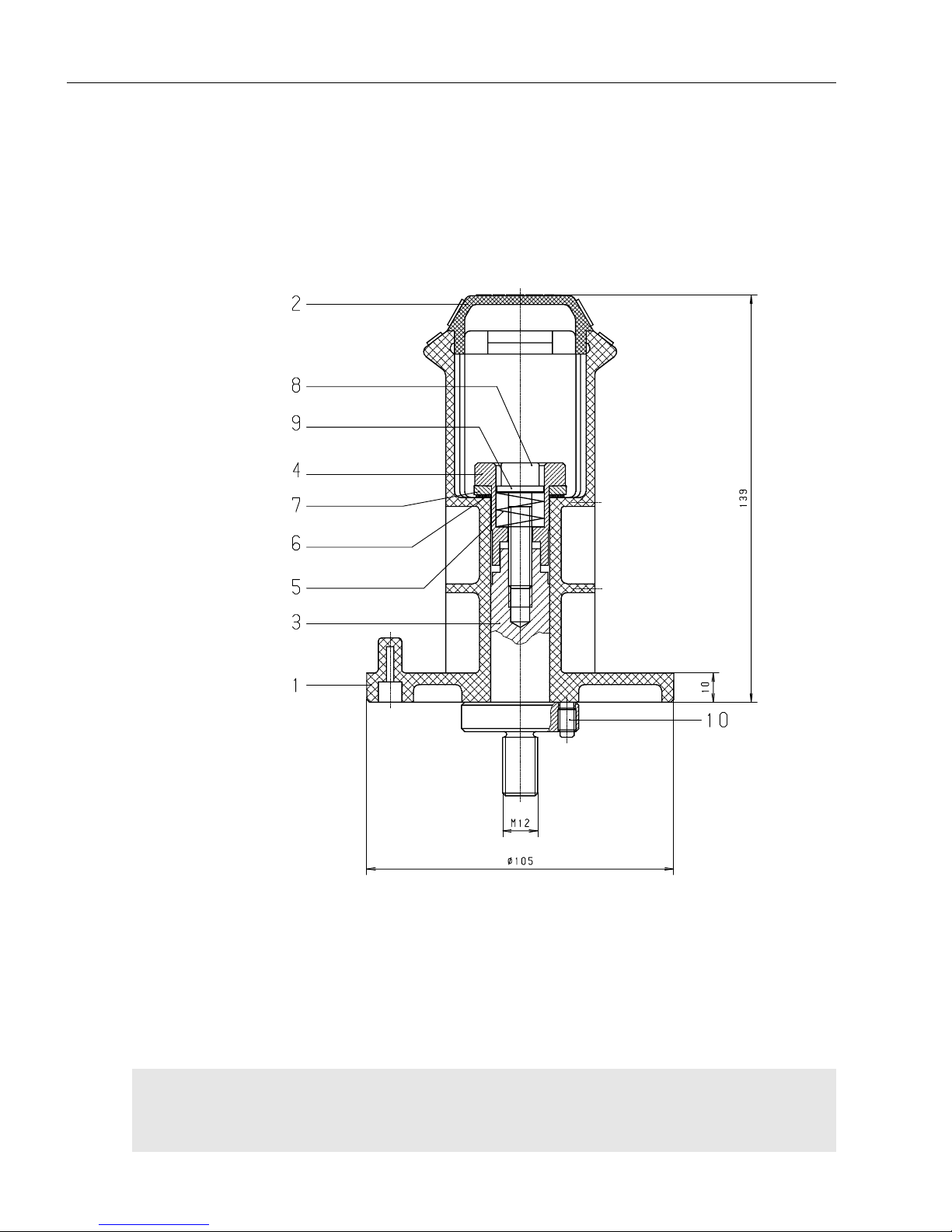
L-23
Elektr. und mech. Beschreibung / electr. and mech.
description / description méc. et électr. GLC 353/503/553 MC3
Drahtvorratsrollenhalterung kpl. Bestell-Nr. 047 12 00 00
Wire coil holder compl. Ref.-No. 047 12 00 00
Support de la bobine de fil cpl. Référence 047 12 00 00
Schnittzeichnung Drahtvorratsrollenhalterung kpl. /
Sectional Drawing: Wire coil holder compl. /
Vue partielle: Support de la bobine de fil cpl.
Page 86
L-24
Elektr. und mech. Beschreibung / electr. and mech.
description / description méc. et électr. GLC 353/503/553 MC3
Ersatzteilliste für Drahtvorratsrollenhalterung komplett / Spare parts list for wire coil holder compl. /
Liste des pièces de rechange pour support de la bobine de fil cpl.
047 12 00 00 Drahtvorratsrollenhalterung komplett / wire coil holder compl. /
support de la bobine de fil compl.
1 047 12 00 01 Dorn / mandrel / mandrin
2 047 12 00 02 Knebel / toggle / garrot
3 047 12 01 00 Führungsdorn kpl. / guide mandrel compl. / mandrin de guidage compl.
4 047 06 02 00 Gegenhalter / holder / contre-support
5 000 02 02 10 Druckfeder / pressure spring / ressort à pression
6 047 06 07 00 Pufferscheibe / buffer disc / disque de tampon
7 047 06 06 00 Bremsscheibe Ø 31,5/20x3 / brake disc Ø 31,5/20x3 /
disque à frein Ø 31,5/20x3
8 102 20 80 35 Inbusschraube M 8 x 35 / allan screw M 8 x 35 / vis à six pans creux M 8 x 35
9 047 06 02 01 Druckscheibe / pressure disc / disque de pression
10 102 40 60 08 Gewindestift M 6 x 8 / threaded pin M 6 x 8 / vis sans tête M 6 x 8
Pos. Bestell-Nr./Ref.-No./ Bezeichnung / Description / Désignation
Référence
Page 87
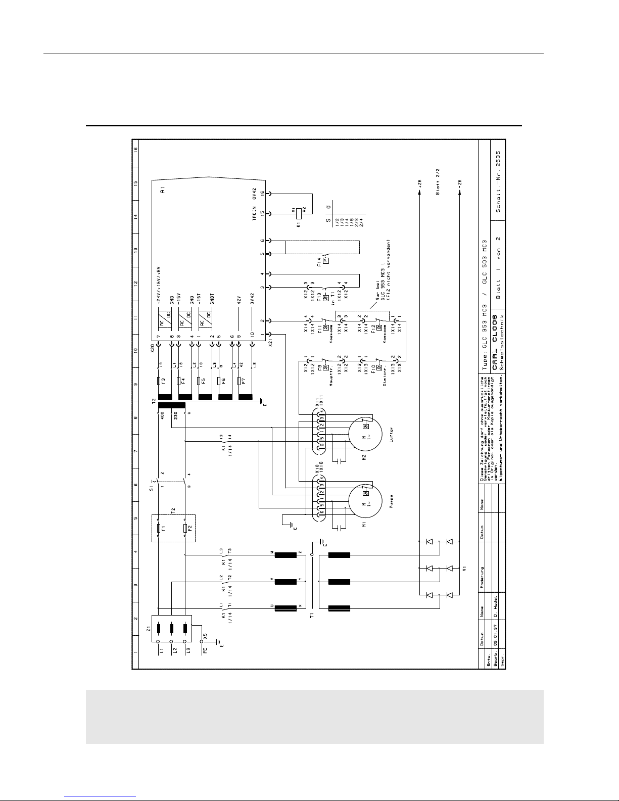
L-25
Elektr. und mech. Beschreibung / electr. and mech.
description / description méc. et électr. GLC 353/503/553 MC3
Blatt 1 von 3 GLC 353/503 MC3 - Schalt.-Nr. 2535
Page 1 of 3 GLC 353/503 MC3 - Diagram No. 2535
Page 1 de 3 GLC 353/503 MC3 - Schéma No. 2535
8. Schaltbilder GLC 353/503 MC3 / Circuit diagrams GLC 353/503 MC3 /
Schémas électriques GLC 353/503 MC3
Page 88
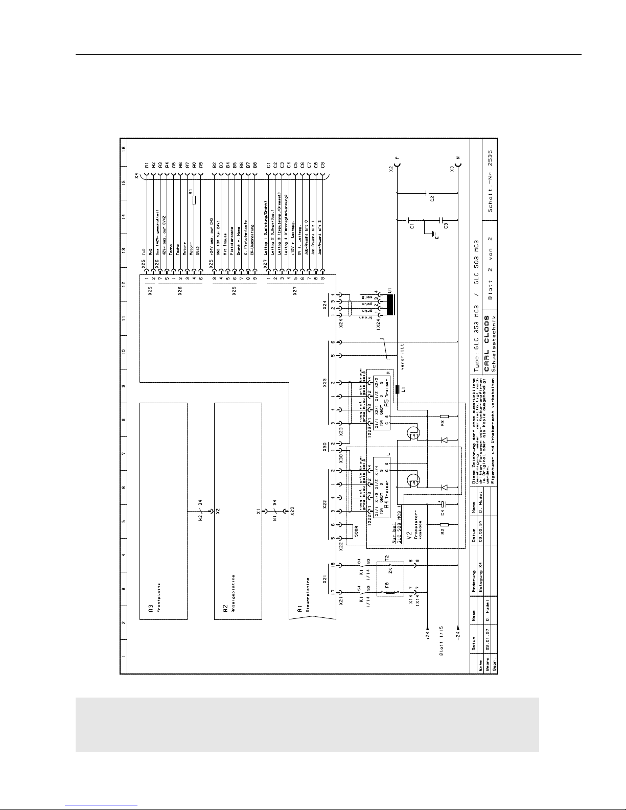
L-26
Elektr. und mech. Beschreibung / electr. and mech.
description / description méc. et électr. GLC 353/503/553 MC3
Blatt 2 von 3 GLC 353/503 MC3 - Schalt.-Nr. 2535
Page 2 of 3 GLC 353/503 MC3 - Diagram No. 2535
Page 2 de 3 GLC 353/503 MC3 - Schéma No. 2535
Page 89
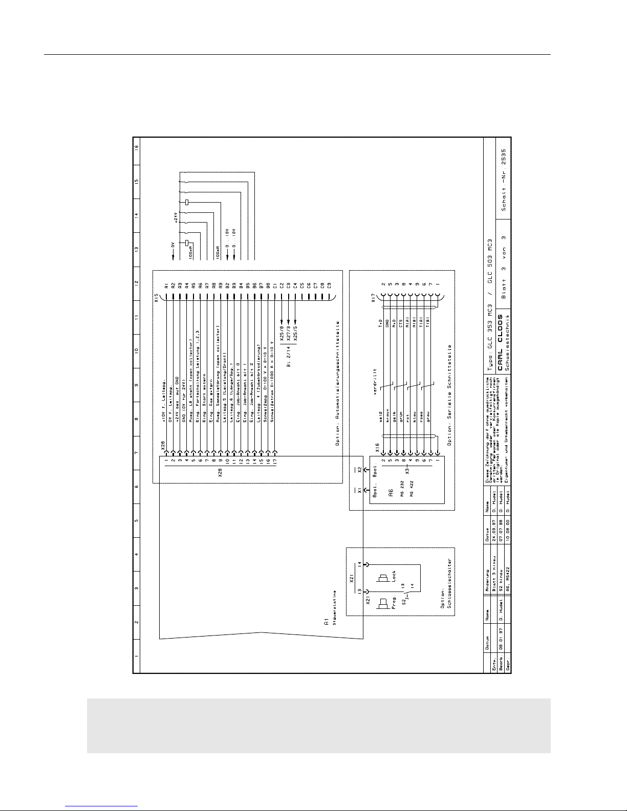
L-27
Elektr. und mech. Beschreibung / electr. and mech.
description / description méc. et électr. GLC 353/503/553 MC3
Blatt 3 von 3 GLC 353/503 MC3 - Schalt.-Nr. 2535
Page 3 of 3 GLC 353/503 MC3 - Diagram No. 2535
Page 3 de 3 GLC 353/503 MC3 - Schéma No. 2535
Page 90
L-28
Elektr. und mech. Beschreibung / electr. and mech.
description / description méc. et électr. GLC 353/503/553 MC3
Elektrische Stückliste - Schalt.-Nr. 2535 / Electrical parts list - diagram No. 2535 /
Liste des pièces électriques - schéma no. 2535
814 70 00 00 GLC 353 MC3
814 80 00 00 GLC 503 MC3
* nur bei GLC 353 MC3 / GLC 353 MC3 only / seulement GLC 353 MC3
+ nur bei GLC 503 MC3 / GLC 503 MC3 only / seulement GLC 503 MC3
A1* 033 05 55 00 Steuerplatine GLC 353 / control board GLC 353/ platine de commande GLC 353
A1+ 033 05 55 10 Steuerplatine GLC 503 / control board GLC 503/ platine de commande GLC503
028 10 03 35 Software EPROM / spftware EPROM / logiciel EPROM
A2 033 05 57 00 Anzeigeplatine / indicating PCB / platine d'indication
A3 090 01 17 63 Frontplatte kpl. /front plate compl. / plaque avant cpl.
A4+ 033 09 70 00 Treiberkarte links 503 / driver card left 503 / carte d'attaque gauche 503
A5+ 033 09 70 10 Treiberkarte rechts 503 / driver card right 503 / carte d'attaque droite 503
A5* 033 09 71 00 Treiberkarte 353 / driver card 353 / carte d'attaque 353
C1 021 02 02 05 Polyesterkondensator 10nF/630V / polyester capacitor 10nF/630V /
condensateur polyester 10nF/630V
C2 021 02 02 05 Polyesterkondensator 10nF/630V / polyester capacitor 10nF/630V /
condensateur polyester 10nF/630V
C3 021 02 02 05 Polyesterkondensator 10nF/630V / polyester capacitor 10nF/630V /
condensateur polyester 10nF/630V
C4 * 021 01 12 98 Elko 10.000µF/63V für Zwischenkreis, an der Transistorkaskade 353
8 Stück parallel /
Elko 10.000µF/63V for intermediate circuit, at transistor cascade 353,
8 pcs. parallel /
Elko 10.000µF/63V pour circuit intermédiaire, sur cascade transistor 353,
8 pcs. parallèle
C4+ 021 01 12 69 Elko 10.000µF/100V für Zwischenkreis, an der Transistorkaskade 503
10 Stück parallel /
Elko 10.000µF/100V for intermediate circuit, at transistor cascade 503,
10 pcs. parallel /
Elko 10.000µF/100V pour circuit intermédiaire, sur cascade transistor 503,
10 pcs. parallèle
F1 016 02 04 01 Sicherung 4A tr. Pumpe, Lüfter, prim. T2 / slow fuse 4A, pump, fan,
primary T2 / fusible à action retardée, pompe, ventilateur, primaire T2
F2 016 02 04 01 Sicherung 4A tr. Pumpe, Lüfter, prim. T2 / slow fuse 4A, pump, fan,
primary T2 / fusible à action retardée, pompe, ventilateur, primaire T2
F3 016 02 04 01 Sicherung 4A tr. sek. Steuertrafo T2, 19V
slow fuse 4A, secondary control transformer T2, 19V
fusible à action retardée 4A, transformateur secondaire de commande T2, 19V
F4 016 02 01 26 Sicherung 0,5A mT sek. Steuertrafo T2, 18V
fuse 0,5A mT secondary control transformer T2, 18V /
fusible 0,5A, transformateur sécondaire de commande T2, 18V
F5 016 02 01 18 Sicherung 1A mT sek. Steuertrafo T2, 18V
fuse 1A mT secondary control transformer T2, 18V /
fusible 1A, transformateur sécondaire de commande T2, 18V
Pos. Bestell-Nr./Ref.-No./ Bezeichnung / Description / Désignation
Référence
Page 91

L-29
Elektr. und mech. Beschreibung / electr. and mech.
description / description méc. et électr. GLC 353/503/553 MC3
Elektrische Stückliste - Schalt.-Nr. 2535 / Electrical parts list - diagram No. 2535 /
Liste des pièces électriques - schéma no. 2535
F6 016 02 01 18 Sicherung 1A mT sek. Steuertrafo T2, 8V
fuse 1A mT secondary control transformer T2, 8V /
fusible 1A, transformateur sécondaire de commande T2, 8V
F7 016 02 01 18 Sicherung 1A mT sek. Steuertrafo T2, 42V
fuse 1A mT secondary control transformer T2, 42V /
fusible 1A, transformateur sécondaire de commande T2, 42V
F8 016 02 01 29 Sicherung 10A tr. Zwischenkreisspg. an A1
slow fuse 10A, intermediate circuit voltage to A1
fusible à action retardée 10A, tension circuit intermédiaire sur A1
F9 016 06 20 00 Thermoschalter im Haupttrafo 160°C ± 10°C
thermal switch in main transformer 160°C ± 10°C
déclencheur thermique dans transformateur principal 160°C ± 10°C
F10 in V1 Thermoschalter im Gleichrichter 100°C ± 5°C
thermal switch in rectifier 100°C ± 5°C
déclencheur thermique dans redresseur 100°C ± 5°C
F11 016 06 22 00 Thermoschalter in Kaskade 80°C ± 5°C
thermal switch in cascade 80°C ± 5°C
déclencheur thermique dans cascade 80°C ± 5°C
F12+ 016 06 22 00 Thermoschalter in Kaskade 80°C ± 5°C
thermal switch in cascade 80°C ± 5°C
déclencheur thermique dans cascade 80°C ± 5°C
F13 016 06 43 00 Thermoschalter im Haupttrafo 70°C ± 5°C
thermal switch in main trnsformer 70°C ± 5°C
déclencheur thermique dans trnsformateur principal 70°C ± 5°C
F14 016 09 09 00 Option: Durchflußwächter im Pistolenkreislauf /
Option: flow switch in torch circuit /
Option: contrôleur de débit dans le circuit de la torche
K1* 012 02 13 50 Schütz Haupttrafo ein 353 / contactor main transformer 'on' 353 /
contacteur transformateur principal marche 353
K1+ 012 02 16 00 Schütz Haupttrafo ein 503 / contactor main transformer 'on' 503 /
contacteur transformateur principal marche 503
012 02 13 55 Hilfsschalterblock für K1 / auxiliary switch for K 1 /
interrupteur auxiliaire pour K1
L1 802 88 35 00 Schweißstromdrossel / welding current choke / self du courant de soudage
M1 023 03 36 00 Pumpe mit Kondensator u. Stecker / pump with capacitor and plug /
pompe avec condensateur et fiche
M2* 022 04 16 00 Lüfter 353 / fan 353 / ventilateur 353
M2+ 022 04 33 00 Lüfter 503 / fan 503 / ventilateur 503
R1 030 04 01 96 Widerstand 1Ohm/50W / resistance 1Ohm/50W / résistance 1 Ohm/50W
R2 030 04 04 01 Entladewiderstand 470Ohm/25W (in V2 enthalten)
discharge resistance 470Ohm/25W (included in V2)
résistance de décharge 470Ohm/25W (incluse dans V2)
R3 030 04 04 02 Widerstand 150Ohm/50W (in V2 enthalten)
discharge resistance 150Ohm/50W (included in V2)
résistance de décharge 150Ohm/50W (incluse dans V2)
Pos. Bestell-Nr./Ref.-No./ Bezeichnung / Description / Désignation
Référence
Page 92

L-30
Elektr. und mech. Beschreibung / electr. and mech.
description / description méc. et électr. GLC 353/503/553 MC3
Elektrische Stückliste - Schalt.-Nr. 2535 / Electrical parts list - diagram No. 2535 /
Liste des pièces électriques - schéma no. 2535
R5 030 01 33 00 Varistor für 42V~, einbaufertig/ varistor for 42V~, ready for installation /
varistor pour 42V~, prêt pour l'installation
S1 003 22 35 00 2pol. Schalter Ein-Aus m. Frontschild u. Griff
2 pole on-off button with front panel and handle
interrupteur marche-arrêt avec façade et poignée
T1* 814 23 00 00 Haupttrafo 353 230/400V / main transformer 353 230/400 V
transformateur principal 353 230/400 V
T1+ 813 23 00 00 Haupttrafo 503 230/400V / main transformer 503 230/400 V
transformateur principal 503 230/400 V
T2 027 05 25 00 Steuertrafo 230/400V-19/18/18/8/42V, 218VA
control transformer 230/400V-19/18/18/8/42V, 218VA
transformateur de commande 230/400V-19/18/18/8/42V, 218VA
U1 028 09 03 04 Stromsensor / current sensor / détecteur de courant
V1* 055 08 17 00 Hauptgleichrichter 353 mit Thermoschalter (in V2 enthalten)
main rectifier 353 with thermal switch (included in V2)
redresseur principal 353 avec déclencheur thermique (inclus dans V2)
V1+ 055 13 02 10 Hauptgleichrichter 503 mit Thermoschalter
main rectifier 503 with thermal switch
redresseur principal 503 avec déclencheur thermique
V2* 055 51 00 00 Transistorkaskade 353 kpl. mit Kondensatorbatterie, Treiberkarte,
Thermoschalter und Hauptgleichrichter /
transistor cascade 353 compl. with capacitor battery, driver card, thermal
switch and main rectifier /
cascade transistor cpl. 353 avec batterie condensateur, carte d'attaque,
commutateur termique et redresseur principal
V2+ 055 45 10 00 Transistorkaskade 503 kpl. mit Kondensatorbatterie, Treiberkarte,
Thermoschalter / transistor cascade 503 compl. with capacitor battery, driver
card, thermal switch / cascade transistor cpl. 503 avec batterie condensateur,
carte d'attaque, commutateur termique
W1 038 13 11 00 Flachbandkabel 34adr. kpl. mit Steckerteilen 260mm lang, Verbindung
Steuerplatine-Anzeige / flat cable 34 wires compl. with plug parts, 260 mm
long, connection control board - display / câble plat à 34 fils cpl. avec fiches,
longueur 260 mm, connexion platine de commande - affichage visual
W2 an A3 Flachbandkabel 34adr. kpl. mit Stecker, Verbindung Frontplatte-Anzeige
flat cable 34 wires compl. with plug parts, 260 mm long, connection front plate/
display / câble plat à 34 fils cpl. avec fiches, longueur 260 mm,
connexion plaque frontale - affichage visuel
X2 073 03 12 00 Schweißstromanschluß Plus, kpl. / welding current connection plus compl. /
raccord courant de soudage plus cpl.
X3 073 03 12 00 Schweißstromanschluß Minus, kpl. / welding current connection minus compl. /
raccord courant de soudage minus cpl.
X4 010 09 10 01 25pol. Anbaugehäuse / 25 pole housing / embase
010 09 18 12 25pol. Buchsenteil / 25 pole multiple socket / prise multiple à 25 pôles
010 09 18 10 Crimpbuchse 0,75-1,0mm2, 25 Stück / crimp bush 0,75-1,0mm2, 25 off /
Pos. Bestell-Nr./Ref.-No./ Bezeichnung / Description / Désignation
Référence
Page 93

L-31
Elektr. und mech. Beschreibung / electr. and mech.
description / description méc. et électr. GLC 353/503/553 MC3
Elektrische Stückliste - Schalt.-Nr. 2535 / Electrical parts list - diagram No. 2535 /
Liste des pièces électriques - schéma no. 2535
douille 0,75-1,0mm2, 25 pcs.
X5 033 04 84 00 PE-Schiene / PE - rail / rail en PE
X10 035 02 03 10 6pol. Gehäuse für Flachsteckhülsen / 6 pole housing for receptacle /
embase à 6 pôles pour alvéole
035 02 00 31 Flachsteckhülse 6,3x1, 5 Stück / receptacle 6,3x1, 5 off /
alvéole 6,3x1, 5 pcs.
1X10 an Pumpe 6pol. Gehäuse für Flachstecker / 6 pole housing for flat plug /
embase à 6 pôles pour fiche plate
an Pumpe Flachstecker 6,3x1, 6 Stück / flat plug 6,3x1, 6 off /
fiche plate 6,3x1, 6 pcs.
X11 035 02 03 10 6pol. Gehäuse für Flachsteckhülsen / 6 pole housing for receptacle /
embase à 6 pôles pour alvéole
035 02 00 31 Flachsteckhülse 6,3x1, 5 Stück / receptacle 6,3x1, 5 off /
alvéole 6,3x1, 5 pcs.
1X11 am Lüfter 6pol. Gehäuse für Flachstecker / 6 pole housing for flat plug /
embase à 6 pôles pour fiche plate
am Lüfter Flachstecker 6,3x1, 6 Stück / flat plug 6,3x1, 6 off /
fiche plate 6,3x1, 6 pcs.
X12 035 02 00 91 4pol. Gehäuse für Flachsteckhülsen / 4 pole housing for receptacle /
embase à 4 pôles pour alvéole
035 02 00 31 Flachsteckhülse 6,3x1, 4 Stück / receptacle 6,3x1, 5 off /
alvéole 6,3x1, 5 pcs.
1X12 035 02 00 42 4pol. Gehäuse für Flachstecker, an Haupttrafo /
4 pole housing for flat plug, at main transformer /
embase à 4 pôles pour fiche plate, sur transformateur principal
035 02 00 41 Flachstecker 6,3x1, 4 Stück / flat plug 6,3x1, 4 off /
fiche plate 6,3x1, 4 pcs.
X13 035 02 00 22 Flachsteckhülse 6,3mm, isoliert 2 Stück / receptacle 6,3 mm, insulated, 2 off/
alvéole 6,3 mm, isolé, 2 pcs.
1X13 an F9 Flachstecker, an Thermoschalter Gleichrichter /
flat plug, at thermal switch, rectifier /
fiche plate, sur commutateur thermique, redresseur
X14 035 02 03 27 8pol. Gehäuse für Flachstecker / 8 pole housing for flat plug /
embase à 8 pôles pour fiche plate
035 02 00 41 Flachstecker 6,3x1, 8 Stück / flat plug 6,3x1, 8 off /
fiche plate 6,3x1, 8 pcs.
1X14 035 02 03 28 8pol. Gehäuse für Flachsteckhülsen, an Kaskade /
8 pole housing for receptacle, at cascade /
embase à 8 pôles pour alvéole, sur cascade
035 02 00 31 Flachsteckhülse 6,3x1, 8 Stück / receptacle 6,3x1, 8 off /
alvéole 6,3x1, 8 pcs.
X20 011 03 67 09 10pol. Buchsengehäuse 3,96, Trafo-Steuerung / 10 pole bushing housing
3,96, transformer control / embase à douille à 10 pôles 3,96, commande
transformateur
011 03 67 02 Crimpbuchse 0,2-0,8mm², verzinnt 10 Stück /
crimp bush 0,2-0,8mm², tinned, 10 off /
Pos. Bestell-Nr./Ref.-No./ Bezeichnung / Description / Désignation
Référence
Page 94

L-32
Elektr. und mech. Beschreibung / electr. and mech.
description / description méc. et électr. GLC 353/503/553 MC3
Elektrische Stückliste - Schalt.-Nr. 2535 / Electrical parts list - diagram No. 2535 /
Liste des pièces électriques - schéma no. 2535
douille crimp 0,2-0,8mm², étamée, 10 pcs.
X21 011 03 67 05 18pol. Buchsengehäuse 3,96, µP-Leistungsteil /
18 pole busing housing 3,96, µP power part /
embase à douille à 18 pôles, µP bloc d'alimentation
011 03 67 02 Crimpbuchse 0,2-0,8mm², verzinnt 10 Stück
crimp bush 0,2-0,8mm², tinned, 10 off /
douille crimp 0,2-0,8mm², étamée, 10 pcs.
X22+ 011 03 67 10 6pol. Buchsengehäuse 5,08, Regler-Treiber L /
6 pole bushing housing 5,08, regulator - driver L /
embase à douille à 6 pôles 5,08, régulateur - driver L
011 03 67 02 Crimpbuchse 0,2-0,8mm², verzinnt 6 Stück
crimp bush 0,2-0,8mm², tinned, 6 off /
douille crimp 0,2-0,8mm², étamée, 6 pcs.
038 07 14 00 Kabel 4x2x0,2mm2 / cable 4x2x0,2mm2 / câble 4x2x0,2mm
2
1X22+ 011 03 67 17 4pol. Buchsengehäuse 5,08, Regler-Treiber L/
4 pole bushing housing 5,08, regulator - driver L /
embase à douille à 4 pôles 5,08, régulateur - driver L
011 03 67 02 Crimpbuchse 0,2-0,8mm², verzinnt 4 Stück
crimp bush 0,2-0,8mm², tinned, 4 off /
douille crimp 0,2-0,8mm², étamée, 4 pcs.
X23 011 03 67 10 6pol. Buchsengehäuse 5,08, Regler-Treiber R /
6 pole bushing housing 5,08, regulator - driver R /
embase à douille à 6 pôles 5,08, régulateur - driver R
011 03 67 02 Crimpbuchse 0,2-0,8mm², verzinnt 6 Stück
crimp bush 0,2-0,8mm², tinned, 6 off /
douille crimp 0,2-0,8mm², étamée, 6 pcs.
038 07 14 00 Kabel 4x2x0,2mm2 / cable 4x2x0,2mm2 / câble 4x2x0,2mm
2
1X23 011 03 67 17 4pol. Buchsengehäuse 5,08, Regler-Treiber R
4 pole bushing housing 5,08, regulator - driver R /
embase à douille à 4 pôles 5,08, régulateur - driver R
011 03 67 02 Crimpbuchse 0,2-0,8mm², verzinnt 4 Stück
crimp bush 0,2-0,8mm², tinned, 4 off /
douille crimp 0,2-0,8mm², étamée, 4 pcs.
X24 011 03 67 14 4pol. Buchsengehäuse 2,54, für Stromsensor /
4 pole bushing housing 2,54, for current sensor /
embase à douille à 4 pôles, pour détecteur courant
011 03 67 15 Crimpbuchse, verzinnt 4 Stück / crimp bush, tinned, 4 off /
douille crimp, étamée, 4 pcs.
038 07 11 00 Kabel 2x2x0,2mm2 / cable 2x2x0,2mm2 / câble 2x2x0,2mm
2
1X24 011 03 67 14 4pol. Buchsengehäuse 2,54, am Stromsensor
4 pole bushing housing 2,54, at current sensor /
embase à douille à 4 pôles, sur détecteur courant
011 03 67 15 Crimpbuchse, verzinnt 4 Stück / crimp bush, tinned, 4 off /
douille crimp, étamée, 4 pcs.
X25 011 03 67 08 9pol. Buchsengehäuse 3,96, µP-CK / 9 pole bushing housing 3,96, µP-CK /
embase à douille à 9 pôles 3,96, µP-CK
011 03 67 02 Crimpbuchse 0,2-0,8mm², verzinnt 9 Stück / crimp bush 0,2-0,8mm²,
tinned, 9 off / douille crimp 0,2-0,8mm², étamée, 9 pcs.
X26 011 03 19 10 7pol. Buchsengehäuse 3,96, Steuerung-CK / 7 pole bushing housing 3,96,
CK control / embase à douille à 7 pôles 3,96, commande CK
011 03 67 02 Crimpbuchse 0,2-0,8mm², verzinnt 7 Stück / crimp bush 0,2-0,8mm²,
tinned, 7 off / douille crimp 0,2-0,8mm², étamée, 7 pcs.
X27 011 03 67 08 9pol. Buchsengehäuse 3,96, µP-CK / 9 pole bushing housing 3,96, µP-CK /
embase à douille à 9 pôles 3,96, µP-CK
011 03 67 02 Crimpbuchse 0,2-0,8mm², verzinnt 9 Stück / crimp bush 0,2-0,8mm²,
Pos. Bestell-Nr./Ref.-No./ Bezeichnung / Description / Désignation
Référence
Page 95
L-33
Elektr. und mech. Beschreibung / electr. and mech.
description / description méc. et électr. GLC 353/503/553 MC3
Elektrische Stückliste - Schalt.-Nr. 2535 / Electrical parts list - diagram No. 2535 /
Liste des pièces électriques - schéma no. 2535
Pos. Bestell-Nr./Ref.-No./ Bezeichnung / Description / Désignation
Référence
tinned, 9 off / douille crimp 0,2-0,8mm², étamée, 9 pcs.
X29 an W1
X30 011 03 67 11 2pol. Buchsengehäuse 5,08, Schirm / 2 pole bushing housing 5,08, screen /
embase à douille 5,08, écran
011 03 67 02 Crimpbuchse 0,2-0,8mm², verzinnt 2 Stück / crimp bush 0,2-0,8mm²,
tinned, 2 off / douille crimp 0,2-0,8mm², étamée, 2 pcs.
Z1 033 35 19 00 Netzentstörfilter 500V/3x32A / interference suppression filter 500V/3x32A /
filtre antiparasite 500V/3x32V
033 17 83 00 Einbausatz Automatisierungsschnittstelle: / Installation kit automation
interface / Kit d'installation interface d'automatisation
X15 010 09 10 01 25pol. Anbaugehäuse / 25 pole housing / embase à 25 pôles
010 09 18 13 25pol. Stiftteil / 25 pole multiple plug / fiche multiple à 25 pôles
010 09 18 03 Crimpstift 0,75 - 1,0 mm² / crimp pin 0,75 - 1,0 mm² / pin 0,75 - 1,0 mm²
X28 011 03 84 00 17pol. Buchsengehäuse 3,96 / 17 pole bushing housing 3,96 /
embase à douille à 17 pôles 3,96
011 03 67 02 Crimpbuchse 0,2 - 0,8mm², verzinnt / crimp bush 0,2 - 0,8mm², tinned /
douille 0,2 - 0,8mm², étamée
034 11 00 11 Aufquetsch-Verbinder / pressure-type connection / connection sertie
033 21 35 00 Einbausatz serielle Schnittstelle:/ Installation kit serial interface /
Kit d'installation interface sériélle
A6 033 25 07 00 Serielle Schnittstelle RS 232/RS 422 /serial interface RS 232/RS 422 / interface
sérielle RS 232/RS 422
X16 010 11 02 76 9pol. D-Sub-Stecker an Schnittstellenkarte / 9 pole D-sub plug on interface
card / sous-fiche D à 9 pôles sur carte d'interface
038 07 14 00 Kabel 4x2x0,2mm² / cable 4x2x0,2mm² / câble 4x2x0,2mm²
X17 010 11 02 77 9pol. D-Sub-Steckdose / 9 pole D-sub socket / sous-prise D à 9 pôles
010 09 13 13 Schraubbolzen mit Mutter UNC/M3 / screw bolt with nut UNC/MC3 /
boulon fileté avec écrou UNC/MC3
033 17 87 00 Einbausatz Schlüsselschalter / Installation kit key operated switch /
Kit de montage interrupteur à clef
S2 008 02 23 07 Drehschloß mit 2 Schlüsseln/ twist lock with 2 keys /
verrou tournant avec 2 clefs
008 02 25 07 Schaltsatz / spring assembly / groupe de contacts
008 02 23 06 Bezeichnungsschild "Prog." / designation crd "Prog" / étiquette "Prog"
033 17 84 00 Einbausatz CO2-Vorwärmersteckdose / Installation kit CO2- preheater socket /
Kit de montage prise pour réchauffeur
X18 010 06 01 00 3pol. Steckdose für CO2-Vorwärmer / 3 pole socket for CO2-preheater /
prise à 3 pôles pour réchauffeur CO
2
T2 027 05 27 00 Steuertrafo /control transformer / transformateur de commande
230/400V-19/18/18/8/42V, 344VA
Page 96
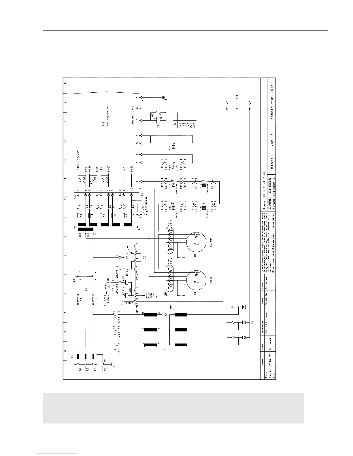
L-34
Elektr. und mech. Beschreibung / electr. and mech.
description / description méc. et électr. GLC 353/503/553 MC3
Blatt 1 von 3 GLC 553 MC3 - Schalt.-Nr. 2549
Page 1 of 3 GLC 553 MC3 - Diagram No. 2549
Page 1 de 3 GLC 553 MC3 - Schéma No. 2549
Page 97
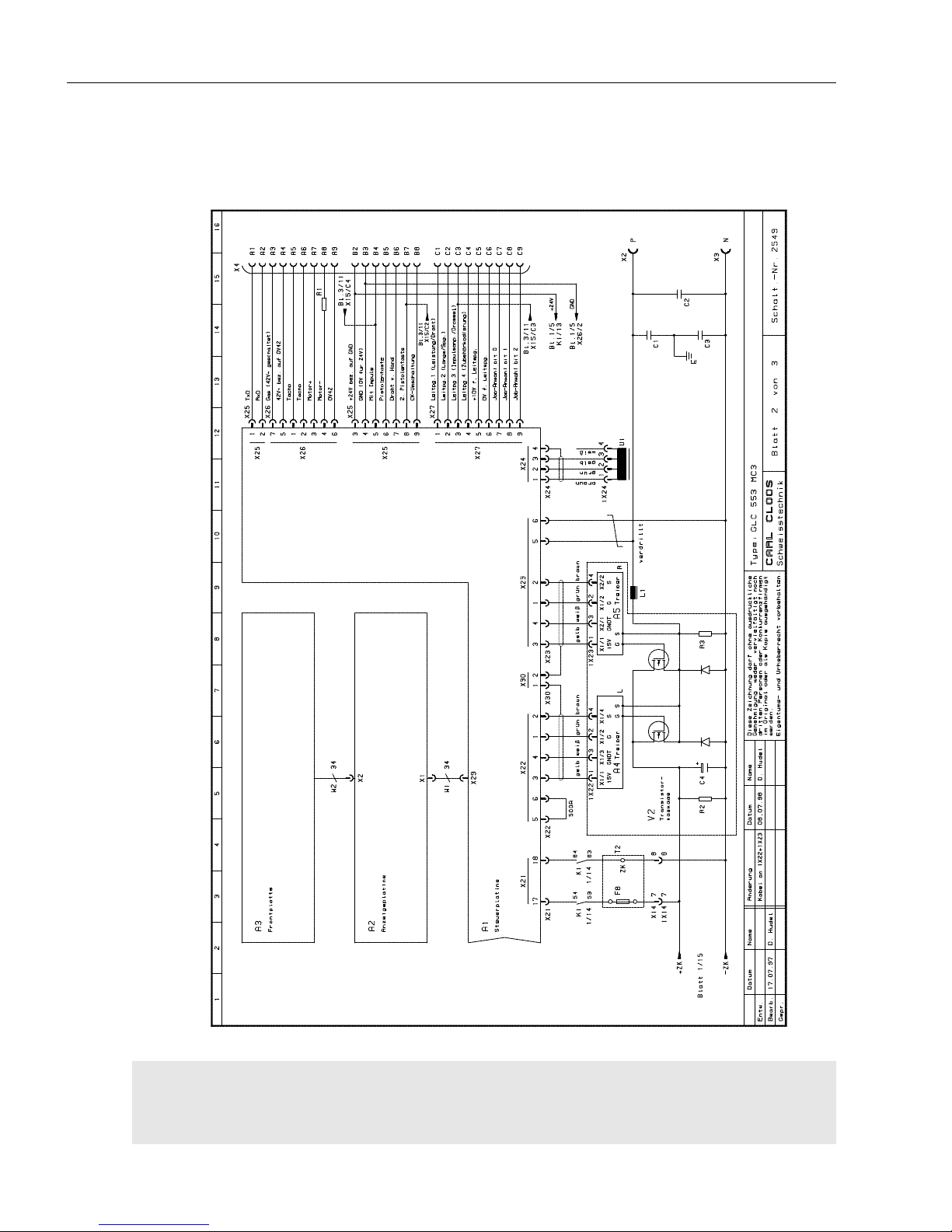
L-35
Elektr. und mech. Beschreibung / electr. and mech.
description / description méc. et électr. GLC 353/503/553 MC3
Blatt 2 von 3 GLC 553 MC3 - Schalt.-Nr. 2549
Page 2 of 3 GLC 553 MC3 - Diagram No. 2549
Page 2 de 3 GLC 553 MC3 - Schéma No. 2549
Page 98
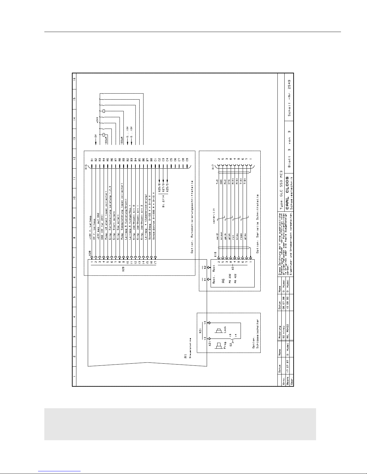
L-36
Elektr. und mech. Beschreibung / electr. and mech.
description / description méc. et électr. GLC 353/503/553 MC3
Blatt 3 von 3 GLC 553 MC3 - Schalt.-Nr. 2549
Page 3 of 3 GLC 553 MC3 - Diagram No. 2549
Page 3 de 3 GLC 553 MC3 - Schéma No. 2549
Page 99

L-37
Elektr. und mech. Beschreibung / electr. and mech.
description / description méc. et électr. GLC 353/503/553 MC3
Elektrische Stückliste - Schalt.-Nr. 2549 / Electrical parts list - diagram No. 2549 /
Liste des pièces électriques - schéma no. 2549
Pos. Bestell-Nr./Ref.-No./ Bezeichnung / Description / Désignation
Référence
818 10 00 00 GLC 553 MC3 / GLC 553 MC3 machine / poste GLC 553 MC3
A1 033 05 55 20 Steuerplatine für GLC 553 MC3 kpl./control board for GLC 553 MC3 compl./
platine pour GLC 553 MC3
028 10 03 35 Software, EPROM / software, EPROM/ logiciel, EPROM
A2 033 05 57 00 Anzeigeplatine
A3 090 01 17 63 Frontplatte kpl. /front plate compl. / plaque frontale cpl.
A4 033 09 70 00 Treiberkarte links /left driver card / carte d'attaque gauche
A5 033 09 70 10 Treiberkarte rechts /right driver card / carte d'attaque droite
A7 033 11 48 30 Steuerplatte Pumpe und Lüfter ein /control board pump and fan on/
platine pompe et ventilateur marche
C1 021 02 02 05 Polyesterkondensator 10nF/630V /polyester capacitor 10nF/630V /
condensateur polyester 10nF/630V
C2 021 02 02 05 Polyesterkondensator 10nF/630V / polyester capacitor 10nF/630V /
condensateur polyester 10nF/630V
C3 021 02 02 05 Polyesterkondensator 10nF/630V / polyester capacitor 10nF/630V /
condensateur polyester 10nF/630V
C4 021 01 12 69 Elko 10.000µF/100V für Zwischenkreis, an der Transistorkaskade
Elko 10.000µF/100V for intermediate circuit, at transistor cascade /
Elko 10.000µF/100V pour circuit intermédiare, sur cascade transisteur
C5 021 01 12 16 Kondensator 12µF/240V für Lüfter Stufe 1 / capacitor 12µF/240V for fan step 1 /
condensateur 12µF/240V pour ventilateur, étage 1
F1 016 02 04 01 Sicherung 4A tr. Pumpe, Lüfter, prim. T2 /
slow fuse 4A, pump, fan, primary transformer T2 /
fusible à action retardée 4A, pompe, ventilateur, transformateur primaire T2
F2 016 02 04 01 Sicherung 4A tr. Pumpe, Lüfter, prim. T2 /
slow fuse 4A, pump, fan, primary transformer T2/
fusible à action retardée 4A, pompe, ventilateur, transformateur primaire T2
F3 016 02 04 01 Sicherung 4A tr. sek. Steuertrafo T2, 19V /
slow fuse 4A, secondary control transformer T2, 19V /
fusible à action retardée 4A, transformateur de commande secondaire T2, 19V
F4 016 02 01 26 Sicherung 0,5A mT sek. Steuertrafo T2, 18V /
fuse 0,5A mT, secondary control transformer T2, 18V /
fusible 0,5A mT, transformateur de commande secondaire T2, 18V
F5 016 02 01 18 Sicherung 1A mT sek. Steuertrafo T2, 18V /
fuse 1A mT, secondary control transformer T2, 18V /
fusible 1A mT, transformateur de commande secondaire T2, 18V
F6 016 02 01 18 Sicherung 1A mT sek. Steuertrafo T2, 8V /
fuse 1A mT, secondary control transformer T2, 8V /
fusible 1A mT, transformateur de commande secondaire T2, 8V
F7 016 02 01 18 Sicherung 1A mT sek. Steuertrafo T2, 42V /
fuse 0,5A mT, secondary control transformer T2, 42V /
fusible 0,5A mT, transformateur de commande secondaire T2, 42V
F8 016 02 01 29 Sicherung 10A tr. Zwischenkreisspg. an A1 /
slow fuse 10A, intermediate circuit voltage at A1 /
fusible à action retardée 10A, tension circuit intermédiaire sur A1
F9 016 06 20 00 Thermoschalter im Haupttrafo 160°C ± 10°C/
thermal switch in main transformer 160°C ± 10°C /
commutateur thermique dans transformateur principal 160°C ± 10°C
F10 in V1 Thermoschalter im Gleichrichter 100°C ± 5°C / thermal switch in rectifier /
commutateur thermique dans redresseur 100°C ± 5°C
F11 016 06 22 00 Thermoschalter in Kaskade 80°C ± 5°C / thermal switch in cascade /
commutateur thermique dans cascade 80°C ± 5°C
F12 016 06 22 00 Thermoschalter in Kaskade 80°C ± 5°C/ thermal switch in cascade /
commutateur thermique dans cascade 80°C ± 5°C
Page 100

L-38
Elektr. und mech. Beschreibung / electr. and mech.
description / description méc. et électr. GLC 353/503/553 MC3
Elektrische Stückliste - Schalt.-Nr. 2549 / Electrical parts list - diagram No. 2549 /
Liste des pièces électriques - schéma no. 2549
Pos. Bestell-Nr./Ref.-No./ Bezeichnung / Description / Désignation
Référence
F13 016 06 43 00 Thermoschalter im Haupttrafo 70°C ± 5°C/thermal switch in main transformer /
commutateur thermique dans transformateur principal 70°C ± 5°C
F14 016 09 09 00 Option: Durchflußwächter / Option: flow switch /Option: contrôleur de débit
K1 012 02 16 00 Schütz Haupttrafo ein / contactor main transformer on /
contacteur transformateur principal marche
012 02 13 55 Hilfsschalterblock für K1 /auxiliary switch for K1 / interrupteur auxiliaire pour K1
L1 802 88 35 00 Schweißstromdrossel / welding current choke /self du courant de soudage
M1 023 03 36 00 Pumpe mit Kondensator u. Stecker / pump with capacitor and plug /
pompe avec condensateur et fiche
M2 022 04 35 00 Lüfter 553, mit Kondensator und Stecker / fan 553, with capacitor and plug /
ventilateur 553, avec condensateur et fiche
R1 030 04 01 96 Widerstand 1Ohm/50W / resistor 1Ohm/50W / résistance 1Ohm/50W
R2 030 04 04 01 Entladewiderstand 470 Ohm/25W (in V2 enthalten) /
discharge resistor 470 Ohm/25W (included in V2) /
résistance de décharge 470Ohm/25W (incluse dans V2)
R3 030 04 04 02 Widerstand 150Ohm/50W (in V2 enthalten)/ resistor 150Ohm/50W (included in
V2) / résisance 150Ohm/50W (incluse dans V2)
R5 030 01 33 00 Varistor für 42V~, einbaufertig/ varistor for 42V~, ready for installation /
varistor pour 42V~, prêt pour l'installation
S1 003 22 35 00 2pol. Schalter Ein-Aus m. Frontschild u. Griff /
2 pole on-off switch with front panel and handle /
interrupteur marche-arrêt à 2 pôles avec face avant et poignée
T1 813 23 00 00 Haupttrafo 230/400V /main transformer / transformateur principal 230/400V
T2 027 05 25 00 Steuertrafo 230/400V-19/18/18/8/42V, 218VA / control transformer /
transformateur de commande 230/400V-19/18/18/8/42V, 218VA
U1 028 09 03 04 Stromsensor /current sensor / détecteur curant
V1 055 13 02 10 Hauptgleichrichter mit Thermoschalter / main rectifier with thermal switch /
redresseur principal avec commutateur thermique
V2 055 45 10 00 Transistorkaskade kpl. mit Kondensatorbatterie, Treiberkarten u.
Thermoschaltern / transistor cascade compl. with capacitor battery, driver cards
and thermal switches / cascade transisteur cpl. avec batterie condensateur,
cartes d'attaques et commutateurs thermiques
W1 038 13 11 00 Flachbandkabel 34adr. kpl. mit Steckerteilen 60mm lang, Verbindung
Steuerplatine-Anzeige / flat cable 34 wires compl. with plug parts 60 mm long,
connection control board - display / câble plat à 34 fils compl. avec fiches,
longueur 60 mm, connexion platine de commande - écran
W2 an A3 Flachbandkabel 34adr. kpl. mit Stecker Verbindung Frontplatte-Anzeige /
flat cable 34 wires compl. with plug, connection front panel - display /
câble plat à 34 fils compl. avec fiches, connexion plaque avant - affichage
X2 073 03 12 00 Schweißstromanschluß Plus, kpl. / welding current connection plus, compl./
raccord courant de soudage plus cpl.
X3 073 03 12 00 Schweißstromanschluß Minus, kpl / welding current connection minus, compl./
. raccord courant de soudage minus cpl.
X4 010 09 10 01 25pol. Anbaugehäuse / 25 pole attached housing / embase à 25 pôles
010 09 18 12 25pol. Buchsenteil / 25 pole bush part / douille à 25 pôles
010 09 18 10 Crimpbuchse 0,75-1,0mm2 / crimp bush 0,75-1,0mm2 / douille 0,75-1,0mm
2
X5 033 04 84 00 PE-Schiene / PE rail / rail PE
X10 035 02 03 10 6pol. Gehäuse für Flachsteckhülsen / 6 pole housing for receptacles /
embase à 6 pôles pour alvéoles
035 02 00 31 Flachsteckhülse 6,3x1 / receptacle 6,3x1 / alvéole 6,3x1
1X10 an Pumpe 6pol. Gehäuse für Flachstecker / 6 pole housing for flat plug /
embase à 6 pôles pour fiche plate
an Pumpe Flachstecker 6,3x1 / flat plug 6,3x1 / fiche plate 6,3x1
X11 035 02 03 10 6pol. Gehäuse für Flachsteckhülsen / 6 pole housing for receptacles /
embase à 6 pôles pour alvéoles
 Loading...