

Page 1
Installation and Use Manual
®
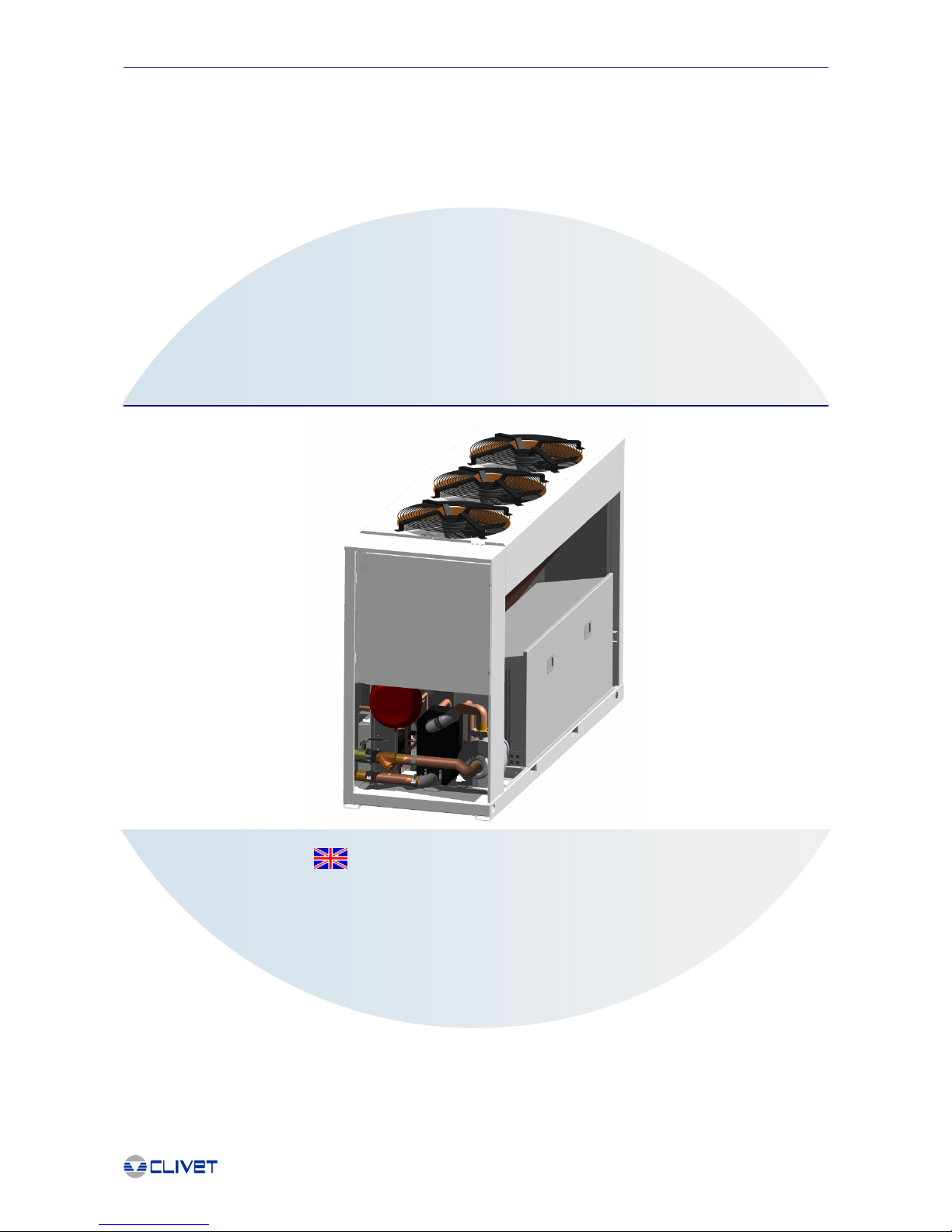
WSAT-2
302-323-404
464-524-564-614
AIR COOLED CHILLER WITH SCROLL COMPRESSORS (WITH PROPELLER FANS)
M91P44E5-05
(R-407C / R-22)
Page 2

Page 3

1
®
- CONTENTS -
GENERAL INFORMATION
GENERAL WARNINGS ............................................................................... 2
CORRECTION FACTORS ...........................................................................2
OPERATION LIMITS AND USE OF THE EXCHANGERS.......................... 2
GENERAL SPECIFICATIONS .....................................................................3
OPERATING LIMITS .................................................................................... 5
SETTING THE CUT-OUT DEVICES AND CONTROLS ............................. 5
SOUND LEVELS ..........................................................................................6
INTENDED USE........................................................................................... 6
ADDITIONAL SAFETY PRECAUTIONS...................................................... 6
REGULATIONS AND CERTIFICATIONS
UNI EN ISO 9001 CERTIFICATION ............................................................7
CE MARK ..................................................................................................... 7
EUROVENT CERTIFICATION ..................................................................... 7
RECEPTION/POSITIONING
INSPECTION UPON RECEPTION .............................................................. 8
STORAGE ....................................................................................................8
HANDLING USING A FORK LIFT OR SIMILAR ......................................... 8
HOISTING USING A CRANE OR SIMILAR................................................. 8
REMOVING THE PACKING ...................................................................... 10
FUNCTIONAL CLEARANCES ...................................................................10
INSTALLATION OF ANTIVIBRATION MOUNTS ......................................10
DIMENSIONS .............................................................................................11
WEIGHT DISTRIBUTION ...........................................................................12
POSITIONING ............................................................................................12
RESIDUAL RISKS
SAFETY INSTRUCTIONS.......................................................................... 13
DEFINITION OF DANGER AREA.............................................................. 13
SAFETY PRESCRIPTIONS ....................................................................... 13
WARNING!.................................................................................................. 13
DANGER!.................................................................................................... 14
PROHIBITIONS ..........................................................................................14
REFRIGERANT SAFETY CHARTS........................................................... 14
DECOMMISSIONING OF THE UNIT
DISCONNECTING THE UNIT .................................................................... 18
DISMANTLING AND DISPOSAL ............................................................... 18
CONTROL
MAIN CONTROL MODULE KE YPAD........................................................ 28
MEANING OF THE BUTTONS ..................................................................28
UNIT ON/OFF............................................................................................. 28
ALARM DISPLAY .......................................................................................28
ALARM RESET ..........................................................................................28
ALARMS ..................................................................................................... 29
ALARM LOG............................................................................................... 29
SELECTING THE OPERATING MODE..................................................... 30
SETTING THE WORKING SET POINT..................................................... 31
SETTING THE ANTIFREEZE SET POINT ................................................ 31
SETTING THE SECOND SET POINT FOR HEATING AND COOLING...32
SETTING THE MAINTENANCE SET POINT ............................................33
SETTING THE CLOCK .............................................................................. 34
SWITCHING ON AND OFF FROM TIME BANDS..................................... 35
CHANGING THE SET POINT FROM TIME BANDS ................................. 35
COUNTER DISPLAY.................................................................................. 37
LAYOUT OF THE MAIN MODULE ............................................................ 38
READING THE OPERATING STATUS .....................................................39
DIGITAL INPUTS ....................................................................................... 40
DIGITAL OUTPUTS ................................................................................... 40
DEMAND LIMIT .......................................................................................... 41
ANTIFREEZE THERMOREGULATOR...................................................... 41
ANTIFREEZE PRE-ALARM THERMOREGULATOR ............................... 42
HIGH PRESSURE ALARM PREVENTION ............................................... 42
FLUID THERMOREGULATOR .................................................................. 42
FLOW ALARM MANAGEMENT .................................................................42
CIRCULATING PUMP MANAGEMENT..................................................... 42
COIL FAN CONTROLLER ......................................................................... 42
COMPRESSOR ROTATION ......................................................................42
CONNECTING THE UNIT TO SUPERVISORY SYSTEMS ......................43
COMMUNICATION PROTOCOL ............................................................... 45
ROUTINE MAINTENANCE
GENERAL................................................................................................... 50
ROUTINE MAINTENANCE ........................................................................50
STRUCTURE.............................................................................................. 50
ELECTRICAL SYSTEM .............................................................................. 50
WATER SYSTEM .......................................................................................50
EXCHANGE COIL ......................................................................................50
WATER EXCHANGER ............................................................................... 50
REFRIGERANTS........................................................................................ 50
TROUBLESHOOTING
GENERAL................................................................................................... 53
FLOW ALARM ............................................................................................53
HIGH PRESSURE ALARM ........................................................................ 53
LOW PRESSURE ALARM ......................................................................... 53
ANTIFREEZE ALARM ................................................................................53
COMPRESSOR THERMAL OVERLOAD ALARM..................................... 53
FAN THERMAL OVERLOAD A LARM........................................................ 53
THE UNIT DOES NOT START .................................................................. 53
THE UNIT IS NOISY................................................................................... 54
WATER/AERAULIC CONNECTIONS
GENERAL................................................................................................... 19
EVAPORATOR PRESSURE DROPS (WATER SIDE) ............................. 20
EVAPORATOR ANTIFREEZE SOLUTIONS ............................................. 20
PUMP PERFORMANCE RELATED TO THE EFFECTIVE PLANT HEAD20
WATER FLOW LIMITS .............................................................................. 21
ELECTRICAL CONNECTIONS
GENERAL................................................................................................... 22
PRELIMINARY OPERATIONS .................................................................. 22
CONNECTING THE MACHINE TO THE MAINS POWER SUPPLY ... 22
FUNCTIONAL CONNECTIONS ................................................................. 22
ENABLING THE SECOND SET POINT FROM DIGITAL INPUT ............. 23
DEMAND LIMIT .......................................................................................... 23
ELECTRICAL DATA ................................................................................... 23
START-UP
GENERAL................................................................................................... 25
PRELIMINARY CHECKS ........................................................................... 25
PRELIMINARY CHECKS: ELECTRICAL SYSTEM .................................. 25
PRELIMINARY CHECKS: REFRIGERANT CIRCUIT ...............................25
PRELIMINARY CHECKS: WATER SYSTEM ............................................ 26
CHECKS ON SAFETY DEVICES, WATER SIDE (DIFFERENTIAL
PRESSURE SWITCH / FLOW SWITCH)............................................. 26
START-UP .................................................................................................. 26
ELECTRICAL CHECKS ............................................................................. 27
REFRIGERANT CIRCUIT CHECKS ..........................................................27
WATER SYSTEM CHECKS ....................................................................... 27
All technical specifications and images presented in this manual are not binding and subject to c hange without notice. Forbidden any
reproduction.
Page 4
2
®
F1 = Cooling capacity correction factors
FK1 = Compressors' input power correction factors
GENERAL WARNINGS
This manual has been designed to enable the unit to be installed, started up and maintained correctly, making it essential to observe
the following points:
- these instructions should be read carefully;
- the unit must be installed, tested and maintained by expert personal who meet the relevant legal requirements (Italian law No. 46 of
5/3/1990).
- The manufacturer declines all liability for any electrical and/or mechanical changes to the unit, which also invalid its guarantee. Any
operations whatsoever that have not been expressly authorised and do not respect the information in this manual shall invalidate the
guarantee.
- Observe the local safety regulations in force when installing the unit.
- Make sure the power supply conforms to the data on the unit’s rating plate, located inside the door of the main electrical panel.
- This manual and the unit’s wiring diagram should be carefully stored so that they are readily available to the operator when required.
- The packaging material (plastic bags, polystyrene foam, nails, etc.) is potentially dangerous and should therefore be kept away from
children and recycled in compliance with the local regulations in force.
- The unit must only be used for the specific purpose it was designed, as described in the paragraph GENERAL TECHNICAL
SPECIFICATIONS Any use other than that specified does not imply any commitment or constraint by the manufacturer in any way
whatsoever.
- Switch off the unit in the event of faults or poor operation.
- Only have repairs carried out by a service centre authorised by the manufacturer, and insist on the use of original spare parts only.
Failure to comply with the above may compromise the safety of the unit.
The manufacturer declines all liability for any damage that may be caused whether directly or indirectly to persons or things if these
instructions are not heeded.
CORRECTION FACTORS
The performance data described in the general technical specifications is based on an evaporator fouling factor of 0.44x10⁻⁴ m2 x°C/
W and perfectly clean finned coils. For different value fouling factors, the performance data must be multiplied by the following
correction coefficients.
OPERATION LIMITS AND USE OF THE EXCHANGERS
- GENERAL INFORMATION-
General Information
CORRECTION FACTORS
m
2
°C / W
F1 FK1
0.44 x 10⁻⁴
1 1
0.88 x 10⁻⁴
0.97 0.99
1.76 x 10⁻⁴
0.94 0.98
Evaporator
Evaporator
DPr DPw Dteo Dtei
[kPa] [kPa] [°C]
S-B S B (*)
CLIVET C
3450 2500 6 -8 22
PED CE
3450 3450 6 -8 22
UDT U
- - 6 -8 22
[°C]
DT
[°C]
5
5
5
DPr = Maximum operating pressure at refrigerant side
DPw = Maximum operating pressure at water side
DTeo = Minimum water temperature at evaporator outlet
DTei = Maximum water temperature at evaporator inlet
DT = inlet / outlet temperature differential
S = Standard
B = Brine
(*) = Limit for 2 capacity steps unit
Page 5
3
®
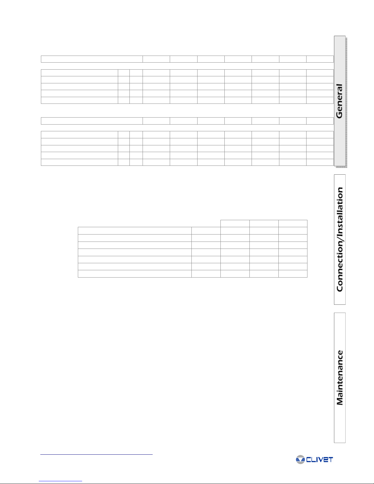
GENERAL SPECIFICATIONS
1. Data refer to the following conditions:
- Evaporator water = 12/7°C
- Ambient temperature = 35°C
Version S / Configuration ST
General Information
SIZE
302 323 404 464 524 564 614
Cooling
Cooling capacity (1) [kW] 81.4 93.5 101.5 119.1 134.3 144.0 159.5
Compr.input power (1) [kW] 26.3 28.6 33.1 37.3 42.0 46.7 54.5
Total input power (1) [kW] 30.2 32.5 37.1 43.0 47.7 52.4 60.2
COMPRESSORS
Compressors type scroll scroll scroll scroll scroll scroll scroll
Nr of compressors 2 3 4 4 4 4 4
Capacity control steps (ST) 2 3 4 4 4 4 4
Oil charge (C1) [l] 4.1 6.6 3.3 3.3 3.3 3.3 4.1
Oil charge (C2) [l] 4.1 3.3 3.3 3.3 3.3 3.3 4.1
Oil charge (C3) [l] 0 3.3 3.3 3.3 3.3 6.6 4.1
Oil charge (C4) [l] 0 0 3.3 3.3 3.3 6.6 4.1
Oil type (*)
Copeland
3MA (32 cSt)
Maneurop
160SZ
Polyolester
ISO32
Maneurop
160SZ
Polyolester
ISO32
Maneurop
160SZ
Polyolester
ISO32
Maneurop
160SZ
Polyolester
ISO32
Maneurop
160SZ
Polyolester
ISO32
Copeland
3MA (32 cSt)
Refrigerant charge (C1) [kg] 14.0 14.0 8.5 8.5 10.5 10.5 11.5
Refrigerant charge (C2) [kg] 14.0 8.5 8.5 8.5 10.5 10.5 11.5
Refrigerant charge (C3) [kg] 0 8.5 8.5 10.5 10.5 11.5 11.5
Refrigerant charge (C4) [kg] 0 0 8.5 10.5 10.5 11.5 11.5
Refrigerant circuits 2 2 2 2 2 2 2
EVAPORATORS
Evaporator type (2) PHE PHE PHE PHE PHE PHE PHE
Evaporator number [l/s] 1 1 1 1 1 1 1
Water flow [l/s] 3.9 4.5 4.8 5.7 6.4 6.9 7.6
Pressure drop [kPa] 29.7 23.8 27.7 27.6 34.6 30.9 37.6
Pump available head [kPa] 130 115 100 120 105 120 110
Water volume [l] 5.9 7.8 7.8 9.4 9.4 11.0 11.0
Outdoor Unit Fans
Evaporator type (3) AX AX AX AX AX AX AX
Evaporator number 2 2 2 3 3 3 3
Fan diametre [mm] 800 800 800 800 800 800 800
RPM [rpm] 870 870 870 870 870 870 870
Standard air flow [l/s] 9150 11650 11650 16650 16650 16650 16100
Single motor input [kW] 2.0 2.0 2.0 2.0 2.0 2.0 2.0
CONNECTIONS
Water connection ["] 2 " 1/2 2 " 1/2 2 " 1/2 2 " 1/2 2 " 1/2 2 " 1/2 2 " 1/2
STANDARD UNIT WEIGHT
Shipping weight [kg] 1347 1473 1548 1666 1695 1746 1789
Operating weight [kg] 1362 1490 1565 1685 1714 1766 1809
DIMENSIONS
Lenght [mm] 3250 3250 3250 3250 3250 3250 3250
Depth [mm] 1095 1095 1095 1095 1095 1095 1095
High [mm] 2030 2030 2030 2030 2030 2030 2030
Packing volume [m
3
] 7 7 7 7 7 7 7
EXPANSION / STORAGE TANK
Expans. tank capacity [l] 12 12 16 16 18 18 18
Max pressure water side [kPa] 800 800 800 800 800 800 800
Nitrogen buffer press. [kPa] 150 150 150 150 150 150 150
N° of expansion tanks 1 1 1 1 1 1 1
Storange tank cap. [l] 200 200 200 200 200 200 200
HYDRAULIC CIRCUIT
Water side max press. [kPa] 550 550 550 550 550 550 550
Safety valve setting [kPa] 600 600 600 600 600 600 600
* R-22 unit:
- Maneurop 160 P Mineral (sizes 323-404-464-524-564)
- SUNISO 3GS (sizes 302-614)
2. PHE = plates
3. AX = axial fan
Page 6
4
®
1. Data refer to the following conditions:
- Evaporator water = 12/7°C
- Ambient temperature = 35°C
Version S / Configuration LN
General Information
* R-22 unit:
- Maneurop 160 P Mineral (sizes 323-404-464-524-564)
- SUNISO 3GS (sizes 302-614)
2. PHE = plates
3. AX = axial fan
SIZE
302 323 404 464 524 564 614
Cooling
Cooling capacity (1) [kW] 79.2 89.6 98.4 115.9 129.1 137.4 153.3
Compr.input power (1) [kW] 27.6 29.8 34.9 39.1 44.1 49.4 57.6
Total input power (1) [kW] 30.1 32.2 37.4 42.6 47.8 52.9 61.2
COMPRESSORS
Compressors type scroll scroll scroll scroll scroll scroll scroll
Nr of compressors 2 3 4 4 4 4 4
Capacity control steps (ST) 2 3 4 4 4 4 4
Oil charge (C1) [l] 4.1 6.6 3.3 3.3 3.3 3.3 4.1
Oil charge (C2) [l] 4.1 3.3 3.3 3.3 3.3 3.3 4.1
Oil charge (C3) [l] 0 3.3 3.3 3.3 3.3 6.6 4.1
Oil charge (C4) [l] 0 0 3.3 3.3 3.3 6.6 4.1
Oil type (*)
Copeland
3MA (32 cSt)
Maneurop
160SZ
Polyolester
ISO32
Maneurop
160SZ
Polyolester
ISO32
Maneurop
160SZ
Polyolester
ISO32
Maneurop
160SZ
Polyolester
ISO32
Maneurop
160SZ
Polyolester
ISO32
Copeland
3MA (32 cSt)
Refrigerant charge (C1) [kg] 14.0 14.0 8.5 8.5 10.5 10.5 11.5
Refrigerant charge (C2) [kg] 14.0 8.5 8.5 8.5 10.5 10.5 11.5
Refrigerant charge (C3) [kg] 0 8.5 8.5 10.5 10.5 11.5 11.5
Refrigerant charge (C4) [kg] 0 0 8.5 10.5 10.5 11.5 11.5
Refrigerant circuits 2 2 2 2 2 2 2
EVAPORATORS
Evaporator type (2) PHE PHE PHE PHE PHE PHE PHE
Evaporator number [l/s] 1 1 1 1 1 1 1
Water flow [l/s] 3.8 4.3 4.7 5.5 6.2 6.6 7.3
Pressure drop [kPa] 28.2 22.0 26.1 26.2 32.1 28.3 34.8
Pump available head [kPa] 130 115 100 120 105 120 110
Water volume [l] 5.9 7.8 7.8 9.4 9.4 11.0 11.0
Outdoor Unit Fans
Evaporator type (3) AX AX AX AX AX AX AX
Evaporator number 2 2 2 3 3 3 3
Fan diametre [mm] 800 800 800 800 800 800 800
RPM [rpm] 870 870 870 870 870 870 870
Standard air flow [l/s] 7220 8890 8890 12770 12770 12770 12200
Single motor input [kW] 1.3 1.3 1.3 1.3 1.3 1.3 1.3
CONNECTIONS
Water connection ["] 2 " 1/2 2 " 1/2 2 " 1/2 2 " 1/2 2 " 1/2 2 " 1/2 2 " 1/2
STANDARD UNIT WEIGHT
Shipping weight [kg] 1378 1504 1579 1697 1726 1777 1820
Operating weight [kg] 1393 1521 1596 1716 1745 1797 1840
DIMENSIONS
Lenght [mm] 3250 3250 3250 3250 3250 3250 3250
Depth [mm] 1095 1095 1095 1095 1095 1095 1095
High [mm] 2030 2030 2030 2030 2030 2030 2030
Packing volume [m
3
] 7 7 7 7 7 7 7
EXPANSION / STORAGE TANK
Expans. tank capacity [l] 12 12 16 16 18 18 18
Max pressure water side [kPa] 800 800 800 800 800 800 800
Nitrogen buffer press. [kPa] 150 150 150 150 150 150 150
N° of expansion tanks 1 1 1 1 1 1 1
Storange tank cap. [l] 200 200 200 200 200 200 200
HYDRAULIC CIRCUIT
Water side max press. [kPa] 550 550 550 550 550 550 550
Safety valve setting [kPa] 600 600 600 600 600 600 600
Page 7
5
®
OPERATING LIMITS
The water flow-rate at the evaporator must be constant and fall within MIN-MAX limits shown in the diagram/diagrams under the
section on "Water/Aeraulic Connections".
Version S / Configuration ST
General Information
Version S / Configuration LN
SETTING THE CUT-OUT DEVICES AND CONTROLS
Opens Closes Value
High pressure switch [kPa] 2800 2000 -
Low pressure switch [kPa] 230 360 Antifreeze protection [°C] 4 6.5 -
High pressure safety valve [kPa] - - 3000
Low pressure safety valve [kPa] - - 1900
Max compressor starts per hour [n°] - - 10
Safety discharge thermostat [°C] - - 120
SIZE
302 323 404 464 524 564 614
Condenser
Max. air inlet temperature (1) [°C] 47.5 47.5 47.5 47 48.5 47 46
Max. air inlet temperature (2) [°C] 53.5 53.5 52.5 52 53 52.5 52
Min. air inlet temperature (3) [°C] -10 -10 -10 -10 -10 -10 -10
Min. air inlet temperature (4) [°C] 6 11 11 10 8 7 5
Min. air inlet temperature (5) [°C] 16 19.5 19.5 19 18 17.5 14.5
SIZE
302 323 404 464 524 564 614
Condenser
Max. air inlet temperature (1) [°C] 44.5 44.5 44.5 44.5 45.5 44 43
Max. air inlet temperature (2) [°C] 50 50 50 50 51 49.5 49
Min. air inlet temperature (3) [°C] -10 -10 -10 -10 -10 -10 -10
Min. air inlet temperature (4) [°C] 6 11 11 10 8 7 5
Min. air inlet temperature (5) [°C] 16 19.5 19.5 19 18 17.5 14.5
1) Unit at full load - Evaporator water = 12/7°C
2) Unit at partial load (automatic partialization)
3) With electronic low ambient temperature control (std), unit at full load and motionless external air
4) With electronic low ambient temperature control (std), unit at partial load and motionless external air
5) With electronic low ambient temperature control (std), unit at partial load with air speed 1m/s
Note: The electronic low ambient temperature control with inverter is recommended for temperatures lower than 5°C
Page 8

6
®
The sound levels refer to:
- units operating at full load
- rated test conditions
SOUND LEVELS
Version S / Configuration ST
Version S / Configuration LN
INTENDED USE
The unit is designed to cool water or a water and glycol mix for air-conditioning, within the limits defined in the technical bulletin and
this manual.
ADDITIONAL SAFETY PRECAUTIONS
This unit has been especially designed and manufactured so to prevent any risk to persons and health hazard.
For this reason, design solutions fit to eliminate (where possible) any cause of risk and sensibly reduce the probability of
danger have been adopted.
Please refer to the "Residual Risks" section of this manual and strictly observe the behaviour prescriptions listed there in order to
prevent any possible risk that hasn’t been possible to avoid in the design stage.
The sound pressure level is measured 1 metre from the surface of the unit operating in an open field.
General Information
Size SOUND POWER LEVEL (dB)
Sound
Pressure
Level
ST
Octave Band (Hz)
63 125 250 500 1000 2000 4000 8000 dB(A) dB(A)
302
90 91 91 88 86 82 75 68 72 91
323
92 94 93 90 88 84 76 70 74 93
404
93 95 94 91 89 85 77 71 75 93
464
95 96 95 93 90 86 78 73 77 95
524
95 96 95 93 91 87 79 73 77 95
564
95 96 95 93 91 87 80 73 77 95
614
95 96 95 93 90 87 80 73 77 95
Sound
Power Level
Size SOUND POWER LEVEL (dB)
Sound
Pressure
Level
LN
Octave Band (Hz)
63 125 250 500 1000 2000 4000 8000 dB(A) dB(A)
302
84 83 82 79 76 72 67 57 63 81
323
86 86 84 80 78 73 67 60 65 83
404
88 88 86 82 80 75 67 62 66 85
464
89 89 87 84 81 75 69 62 67 86
524
89 89 87 85 82 75 70 62 68 86
564
89 89 87 84 81 76 71 62 68 86
614
88 88 87 83 81 77 72 62 68 86
Sound
Power Level
Data calculated according to ISO 3744
Page 9
7
®
- REGULATIONS AND CERTIFICATIONS -
UNI EN ISO 9001 CERTIFICATION
Clivet S.p.A., in order to guarantee customer satisfaction, has chosen the ISO 9001 Quality
System as the reference for all its business activities. This is demonstrated by the
company’s commitment to ongoing improvements in the quality and reliability of its
products; its sales, design, purchasing, production and after-sales service activities are the
means used to reach such purpose.
CE MARK
Clivet products bear the CE mark, in compliance with the requirements of the following EC directives, including the
latest amendments, and with the corresponding national approximated legislation:
- 98/37/CE
- 89/336/CEE as modified by the directives 92/31/CEE and 93/68/CEE
- 73/23/CEE as modified by the directive 93/68/CEE
EUROVENT CERTIFICATION
Clivet is partecipating in the EUROVENT Certification Programme "Liquid Chilling Packages". Products are listed
in the EUROVENT Directory of Certified Products and in the site www.eurovent-certification.com. Eurovent Chillers Certification Programme covers air cooled packaged chillers up to 600 kW and water cooled packaged chillers
up to 1500 kW.
Regulations and Certifications
- 97/23/CE according to H module
CERTIFIED QUALITY SYSTEM
UNI EN ISO 9001:2000
Page 10

8
®
INSPECTION UPON RECEPTION
The units are shipped in special protective packaging. Check upon receipt that the unit has not been damaged during transport, and
that all the parts ordered are present. In the event of visible damage, immediately note the damage found on the shipping document,
writing: "ACCEPTED WITH RESERVATION DUE TO EVIDENT DAMAGE TO THE PACKAGING", as both freight-paid and freightcharged deliveries are covered by insurance in accordance with Italian law no. 450, 22/08/85, "limits of compensation".
IMPORTANT
ALL THE FOLLOWING OPERATIONS MUST BE CARRIED OUT IN COMPLIANCE WITH THE SAFETY STANDARDS IN FORCE,
RELATING TO BOTH THE EQUIPMENT AND THE METHODS USED.
CAUTION
BEFORE PERFORMING THE HANDLING OPERATIONS, CHECK THAT:
- THE HOISTING CAPACITY IS SUITABLY-RATED FOR THE WEIGHT OF THE UNIT IN QUESTION
- THE DISTRIBUTION OF THE WEIGHTS AND THE POSITION OF THE CENTRE OF GRAVITY MUST BE CAREFULLY
CONSIDERED
WARNINGS
FOLLOWING THE SUGGESTIONS INDICATED ON THE OUTSIDE OF THE PACKAGING WILL ENSURE THAT THE UNIT IS
PHYSICALLY INTACT AND FUNCTIONAL, TO THE BENEFIT OF THE END USER. THEREFORE, PLEASE HEED THE
FOLLOWING WARNINGS:
- HANDLE WITH CARE
- KEEP DRY
- AVOID STACKING OTHER OBJECTS ON THE UNIT AT ALL COSTS (UNLESS THIS FALLS WITHIN THE LIMITS OF STACKED
LEVELS SHOWN ON THE PACKAGING).
- AVOID POSITIONING THE UNITS WITH PROTECTIVE HEAT-SHRINK PACKAGING IN DIRECT SUNLIGHT, AS THE
PRESSURE IN THE CIRCUITS MAY REACH VALUES AT WHICH THE SAFETY VALVES ARE ACTIVATED.
STORAGE
- Shelter from: direct sunlight, rain, sand and wind
- Temperature: maximum 60°C minimum -10°C
- Maximum humidity: 90%
- RECEPTION/POSITIONING -
HOISTING USING A CRANE OR SIMILAR
Position the lifting pipes, supplied, in the holes on the base of the unit.
Position the ends of the pipes that protrude from the unit so that the safety pins (supplied) can be placed in the corresponding holes.
Fit the lifting belts over the pipes between the safety devices and the base of the unit (see drawing).
Gradually bring the lifting belts under tension, making sure they are positioned correctly. Make sure the unit is always in steady
equilibrium.
Start hoisting the unit.
Once the unit has been positioned, remove the lifting pipes. These must be kept in a safe place, where they cannot damage people or
property, for any future positioning of the unit.
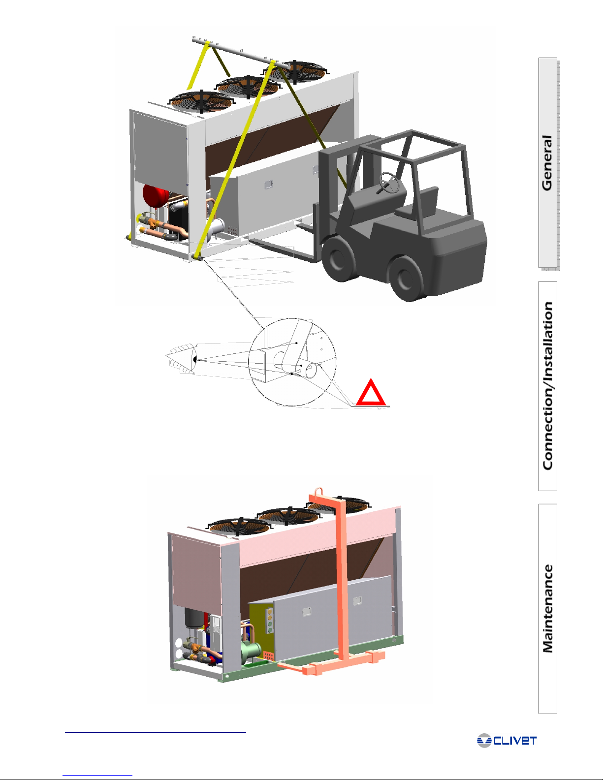
HANDLING USING A FORK LIFT OR SIMILAR
Insert the forks in the long side of the base, in the corresponding slots.
Start hoisting the unit, making sure the load is in steady equilibrium.
Reception/Positioning
Page 11
9
®
!
HOISTING USING A SELF-BALANCING FORK
Insert the self-balancing fork in the special slits of the unit. A rigid protective structure should be placed on the upper edge of the unit,
on the side facing the fork.
Start hoisting the unit, making sure the load is in steady equilibrium.
Reception/Positioning
Page 12

10
®
PLAN OF SPRING ANTIVIBRATION MOUNTS
1. n°4 holes Ø12
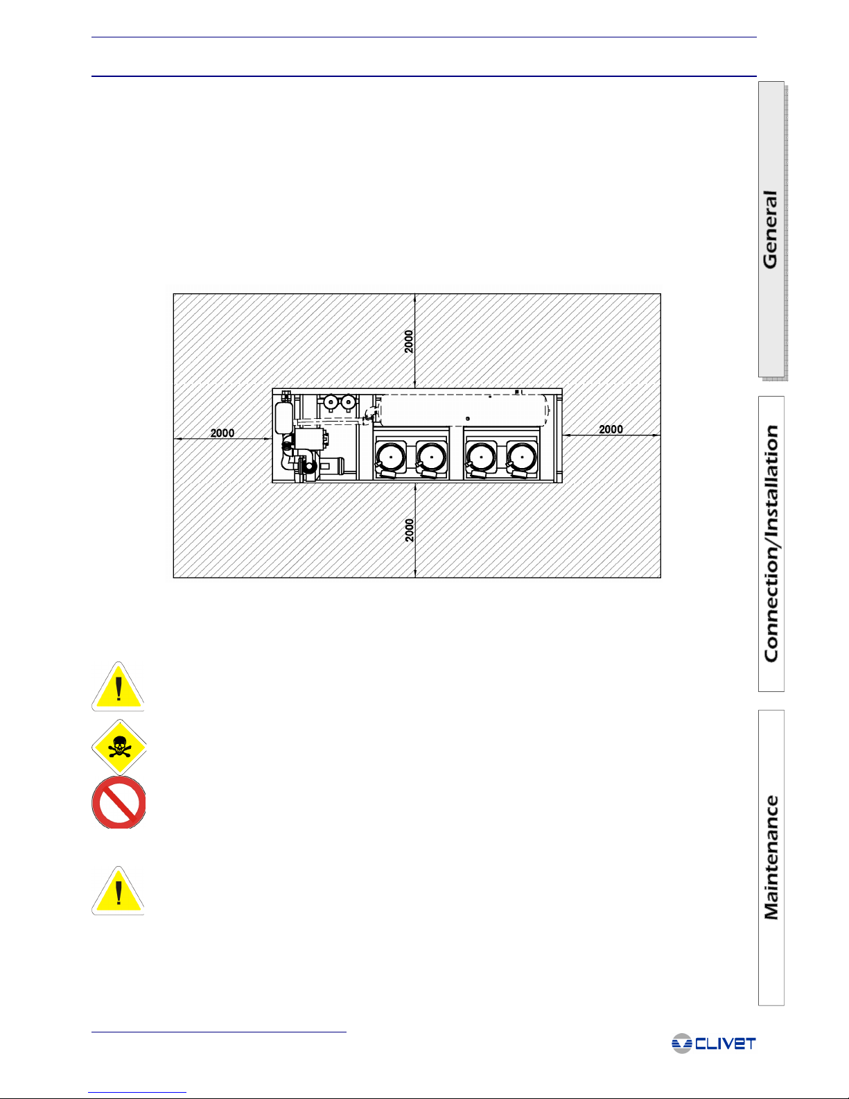
FUNCTIONAL CLEARANCES
IMPORTANT
WHEN PLACING THE UNIT, PLEASE MAKE SURE THAT THE FUNCTIONAL CLEARANCES ALLOW ALL MAINTENANCE
OPERATIONS TO BE PERFORMED. THIS IS REQUIRED FOR OPTIMUM UNIT OPERATION AND PARTICULARLY FOR THE
SAFETY OF AUTHORISED PERSONNEL AND EXPOSED PERSONS
The units require minimum clearances for operation and maintenance. In the event of multiple units, the functional clearances must be
doubled. The following sketches regard some types of installation; check on a case-by-case basis, considering the information
provided in this manual.
INSTALLATION OF ANTIVIBRATION MOUNTS
Spring or rubber (depending on the type of unit) antivibration mounts can be supplied upon request; in this case flexible joints (not
supplied by Clivet) are required for the hydraulic / aeraulic / refrigerant connections.
The tables and the drawings show the instructions for the installation of the antivibration mounts, with the part numbers of the
antivibration kits and their composition for correct installation.
The kits also include the assembly instructions.
INSTALLATION WITH JACK FOR UNIT LEVELLING
1. Minimum dimensions suggested
2. Jack
3. Plate
4. Clamps drowned in the concrete (not supplied)
5. Concrete foundation
* Unloaded height
INSTALLATION DIRECT-TO-FRAME
1. Minimum dimensions suggested
2. Clamps drowned in the concrete (not supplied)
3. Concrete foundation
* Unloaded height
Reception/Positioning
REMOVING THE PACKING
When removing the packaging the operator should, for personal safety, use suitable protective materials (gloves, glasses etc.)
Check for any visible damage.
Dispose of the packaging by taking it to specialist collection or recycling centres (in accordance with local regulations).
Remove the polystyrene packaging and the corresponding fasteners, making sure not to damage the unit.
1
5
0
0
1
5
0
0
1500
900
1
2
3
4
5
2
3
1
1
Page 13

11
®
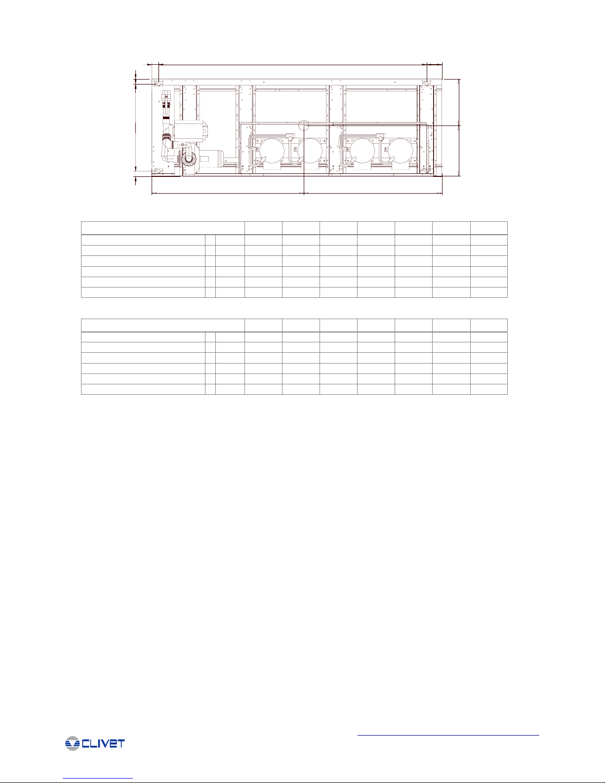
The tables refer to standard units. For special units or versions R, D, etc., refer to the unit dimensional drawings.
Reception/Positioning
UNIT CODE POSITIONING
302 PE581072
W1 = cod. C6100080 K=21,2
W2 = cod. C6100080 K=21,2
W3 = cod. C6100080 K=21,2
W4 = cod. C6100080 K=21,2
323
404 W1 = cod. C6100080 K=21,2
464 W2 = cod. C6100082 K=25,6
524 W3 = cod. C6100080 K=21,2
564 W4 = cod. C6100082 K=25,6
614
PE581051
ANTIVIBRATION MOUNTS CODES
DIMENSIONS
W3
11 11
2
33
7
7
W1 W2
W4
10
MN
O
W3
W1 W2
W4
P
W3
W1 W2
W4
"G"
977
W
9
59
175299085
59
977
L
861
2990
9
8
160
85
11
4-5
12
148
6
2
4-5
148
6
200
350
175
59
4-5
8
H
59
4-5
10
KEY:
1. Compressor
2. Evaporator
3. Condenser
4. Unit mounts holes
5. Belt lifting holes
6. Fork lift lifting holes
7. Electrical panel
8. Power supply input
9. Sound proof enclosure
10. Centrifugal water Pump
11. Evaporator water inlet
12. Evaporator water outlet
Version S / Configuration ST
Version S / Configuration LN
SIZES 302 323 404 464 524 564 614
H
mm 2030 2030 2030 2030 2030 2030 2030
L
mm 3250 3250 3250 3250 3250 3250 3250
M
mm 1628 1675 1703 1701 1708 1722 1733
N
mm 1622 1575 1547 1549 1542 1528 1517
O
mm 523 544 554 557 559 564 568
P
mm 572 551 541 538 536 531 527
W
mm 1095 1095 1095 1095 1095 1095 1095
OD
“ 2" 1/2 2" 1/2 2" 1/2 2" 1/2 2" 1/2 2" 1/2 2" 1/2
SIZES 302 323 404 464 524 564 614
H
mm 2030 2030 2030 2030 2030 2030 2030
L
mm 3250 3250 3250 3250 3250 3250 3250
M
mm 1637 1682 1709 1707 1714 1727 1738
N
mm 1613 1568 1541 1543 1536 1523 1512
O
mm 529 548 558 561 563 568 572
P
mm 566 547 537 534 532 527 523
W
mm 1095 1095 1095 1095 1095 1095 1095
OD
“ 2" 1/2 2" 1/2 2" 1/2 2" 1/2 2" 1/2 2" 1/2 2" 1/2
Page 14
12
®
Version S / Configuration ST
Version S / Configuration LN
WEIGHT DISTRIBUTION
POSITIONING
The units have been designed for outdoor installation in a fixed position.
Check that the fastening/support points are in level and can bear the weight of the unit (see weights and weight distribution).
Avoid installation in areas that may be subject to flooding.
Installations below ground level or near very high walls must be carefully assessed.
Place a layer of rubber between the base of the unit and the support to prevent noise and vibrations. Depending on the place of
installation (balconies or roofs), the unit should be placed on special antivibration mounts (in this case, flexible joints are required for
the water/aeraulic connections - joints are not supplied by Clivet).
Fasten the unit to the ground.
The choice of the location of the unit is of fundamental importance for correct operation. Obstacles that block the flow of air, difficulty
in air circulation, leaves or other objects that may block the exchanger coils, winds that contrast or excessively assist the air flow,
phenomena of stratification or air re-circulation and nearby sources of heat, can cause operating anomalies (increases in condensing
pressure, and consequently decreases in performance) or the shut-down the machine (due to high pressure).
Reception/Positioning
W3
W1 W2
W4
MN
O
W3
W1 W2
W4
P
W3
W1 W2
W4
"G"
5
9
175299085
5
9
9
7
7
SIZES 302 323 404 464 524 564 614
W1 kg 346 352 355 380 383 386 389
W2 kg 369 399 418 447 454 467 477
W3 kg 313 346 364 395 401 413 423
W4 kg 333 392 428 463 476 499 519
Operating weight kg 1361 1489 1565 1685 1714 1765 1808
Shipping weight kg 1347 1473 1548 1666 1695 1746 1789
SIZES 302 323 404 464 524 564 614
W1 kg 348 354 357 382 384 388 391
W2 kg 375 405 424 453 460 473 483
W3 kg 322 355 373 403 410 422 432
W4 kg 348 407 443 478 491 514 534
Operating weight kg 1393 1521 1597 1716 1745 1797 1840
Shipping weight kg 1378 1504 1579 1697 1726 1777 1820
Page 15
13
®
Residual Risks
- RESIDUAL RISKS -
SAFETY INSTRUCTIONS
CAUTION
THIS BULLETIN DESCRIBES EVERY OPERATION THAT MAY CAUSE A SITUATION OF RISK, AS WELL AS THE
PRECAUTIONARY MEASURES TO BE HEEDED IN EACH CASE
The figure below highlights the area in which only authorised personnel may operate.
- External danger zone, identified by a precise area around the unit and its vertical projection on the ground in the case of
hanging unit.
- Internal danger zone, identified by the area that can be entered only after having intentionally removed the protecting panels or parts
of these.
DEFINITION OF DANGER AREA
- WARNING: if used improperly may lead to serious injury
To avoid injury to the user, third parties or the authorised personnel and damage to property, the following instructions MUST be
heeded; incorrect use due to these instructions being neglected may cause damage or injury, the seriousness of which is classified
according to the following symbols:
SAFETY PRESCRIPTIONS
- PROHIBITION: may damage the appliance and consequently the health of the user
- DANGER: may lead to serious injury, death, etc.
WARNING!
- Always contact authorised personnel for the maintenance and repair of this appliance. Contact a qualified installer for
the installation. This appliance has not been designed to be used by children or incapable people without supervision.
Keep out of the reach of the children and their games.
- Use only suitable components for the maintenance operations. The use of defective components may cause injuries or water leaks,
fires, electric shock, falls involving the unit and/or the appliance, …
- Use the specified wires for connecting the appliance to the electrical system and properly connect the cables to the connection
sections so that the stress from the wires not is applied to the sections. Incomplete or insecure connections may cause fires.
- Always contact authorised personnel for the maintenance and repair of this appliance. Contact a qualified installer for the installation.
This appliance has not been designed to be used by children or incapable people without supervision. Keep out of the reach of the
children and their games.
Page 16

14
®
- Installation must be performed following all the safety standards, with reference to the installation manual. Incomplete
or incorrect installation may cause serious personal injury, as the result of fire, electric shock, the falling of the unit or
water leaks.
- Avoid accidental contact with the compressors and outlet tubing, as this may cause burns and injuries. Always use protective gloves.
- Avoid entering the danger zone. Use appropriate clothing and glasses. The expelling of the refrigerant gas due to the activation of
the fuse plug or the safety valves may cause injuries and intoxication.
- Incorrect installation may cause water leaks, electric shocks or fires; contact an authorised reseller or specialised installer, keeping in
mind that faults caused by incorrect installation are not covered by warranty. The units must be installed in an easily accessible site:
any additional costs resulting from the hire of special equipment for the maintenance of the unit are completely at the customer’s
expense.
- Do not use the switch with wet hands. This may cause electric shocks.
- Never clean the appliance using water. This may penetrate into the unit and damage the insulation, and possibly cause electric
shocks.
- Do not insert objects in the air outlets or inlets. As the fan works at high speed, this may cause injuries or damage the unit.
- Securely fasten the cover of the unit’s electrical components. Failure to fasten the cover properly may lead to fires and electric
shock, due to dust, water, ...
- Use protective gloves to avoid injury due to contact with sharp edges.
- Never place a combustion appliance directly below the flow of air to the appliance. This may have negative affects on the
combustion process.
- Keep pets and plants away from the flow of air. They may be injured or damaged.
- Never touch the ventilation fins when the appliance is in operation. The blades may cause injuries.
- Carefully check that the unit is secured to the ground to avoid injury due to the unit tipping over.
DANGER!
- Never leave any compressor outlet and inlet valves closed when the machine is off. This may cause explosion due to an increase in
the room temperature (fires), with the consequent possibility of injuries, intoxication, serious burns, death.
- Securely install the appliance at a point that is able to support the entire weight of the appliance. Installation at points that are not
sufficiently secure may cause the appliance to fall and consequently cause possible injury and damage.
Residual Risks
R-407C
IDENTIFYING ELEMENTS FOR THE SUBSTANCE
- Product name: forane 407C N°SDS 01965/1
- Supplier: ELF ATOCHEM ITALIA, Via G.Murat 17, 20159 Milano tel. 02/668111
COMPOSITION
Chemical nature of the compound: mixture based on:
- Forane 32(difluoromethane) (N° CAS: 75-10-5)
- Forane 125 (pentafluoroethane) (N° CAS: 354-33-6)
- Forane 134a (1.1.1.2 tetrafluoroethane) (N° CAS: 811-97-2)
REFRIGERANT SAFETY CHARTS
- Avoid accidental contact with the exchanger coils, by always using protective gloves and applying the special protective grilles.
Contact may cause minor injuries.
- In the case of anomalies (burning smell, smoke) stop the appliance and turn off the automatic switch. Continuing to operate the unit
in abnormal conditions may cause fire, damage, etc. Contact the manufacturer’s authorised service centre.
- Check that there are no refrigerant gas leaks once installation has been completed.
- Do not install the appliance in sites where there are sporadic or possible leaks of flammable gas. If gas accumulates in
the area surrounding the unit, explosions may occur.
- Never turn the unit on or off using the mains switch. This may cause electric shock or fires due to the generation of heat.
- Make sure the main isolator switch is open and padlocked before removing guards, in that contact with the live parts that are
accessible after having removed the guards may cause death by electrocution or serious burns.
- Pay special attention when earthing the metal earth of the machine, making sure that the metal earth is not live and may thus cause
death by electrocution.
- No repairs may be performed by the customer. Carrying out such operations incorrectly may lead to fires, electric shock,
injuries from the unit falling, water leaks, etc. Contact the manufacturer’s authorised service centre.
- Pay special attention to the correct sizing of the cables and the protection devices on the mains power connection line, so as to avoid
possible fires due to short circuits or the overheating of the cables upstream of the machine’s isolator switch, which may cause death
by serious burns and intoxication.
PROHIBITIONS
Page 17

15
®
Residual Risks
IDENTIFICATION OF RISK
Greatest physical and chemical dangers:
- Thermal decomposition in toxic and corrosive products
FIRST-AID MEASURES
General information:
- Inhalation: Carry the victim into the open air. Resort to oxygen or artificial respiration if necessary.
- Contact with skin: Frostbite must be treated in the same way as burns.
- Contact with the eyes: Immediate rinsing in abundant water. If irritation should continue, consult an ophthalmologist.
- Medical instructions: Do not administer catecholamines (due to the cardiac sensitisation caused by the product).
FIRE PREVENTION MEASURES
- Specific dangers: Thermal decomposition into toxic and corrosive products. Hydrofluoric acid. Carbon monoxides.
- Specific means of intervention: Cool containers/cisterns with jets of water. Prevent any sparks or flames.
- Do NOT smoke.
- Special protection systems for fire-fighting squads: Carry breathing apparatus and wear protective clothing.
MEASURES TO TAKE IN CASE OF ACCIDENTAL SPILLAGE
- Individual precautions: Avoid contact with the skin, eyes and inhalation of vapours. Use personal protection devices.
- In an enclosed space: ventilate or use breathing apparatus (risk of suffocation). NO SMOKING ALLOWED.
- Precautions for environmental protection: Minimise the amount of waste deposited in the environment.
MANIPULATION AND STORAGE
- Technical measures/precautions: Form of storage and manipulation applicable to the products: PRESSURIZED GAS. Ensure
adequate ventilation and evacuation for the level of equipment.
- Advice for use: Prevent sparks and contact with hot surfaces. DO NOT SMOKE.
- Technical measures/Storage procedures: Store at room temperature in the original container. Keep away from flames, hot surfaces
and sparks. Store in a cool, well-ventilated place. Protect full containers from sources of heat to avoid excessive pressures.
- Recommended: Ordinary steel.
- Avoid: Alloy containing more than 2% magnesium. Plastics.
CONTROL OF INDIVIDUAL EXPOSURE/PROTECTION
- Precautionary measures to be taken: Ensure a sufficient exchange of air and/or suction in workplaces.
- Control parameters.
Exposure limits: There is no F-USA limit value
Forane 134a Elf recommended limit value: VME=1000ppm
Forane 32 Elf recommended limit value: VME=1000ppm
Forane 125 Elf recommended limit value: VME=1000ppm
- Protections:
Respiratory protection: In case of insufficient ventilation, carry suitable breathing apparatus.
Protection for the hands: Gloves
Protection for the eyes: Protective eyewear.
PHYSICAL AND CHEMICAL PROPERTIES
- Physical state (20°C): liquid gas
- Colour: colourless
- Smell: Slightly similar to ether; pH: not applicable.
- Boiling point/interval: -42,4 °C
- Melting point/interval: Not inflammable in test conditions
- Vapour pressure: (25°C): 1.13 Mpa (11,3 bar) a (50°C): 2.11 Mpa (21,1 bar) a (70°C): 3.26 Mpa (32,6 bar)
- Vapour density: At boiling point 4,54 kg/m3
- Density: (25°C) 1133 kg/m3 a (50°C) 1004 kg/m3 a (70°C) 861 kg/m3
STABILITY AND REACTIVITY
- Conditions to avoid: Avoid contact with flames and red-hot metal surfaces.
- Dangerous decomposition products: Thermal decomposition into toxic and corrosive products: Toxic fluorinates Hydrogen fluoride
(hydrofluoric acid) .
- Further information: Product stable in normal storage and handling conditions.
TOXICOLOGICAL INFORMATION
- Inhalation: Practically non-toxic in experiments conducted on animals Forane 134a, 32, 125. No rat mortality at 500000 ppm/4h. As
with other volatile aliphatic halogenated compounds, with the accumulation of vapours and/or the inhalation of large quantities, the
product can cause: loss of consciousness and heart problems aggravated by stress and lack of oxygen; risk of death.
- Contact with skin: Frostbite possible from splashes of liquefied gas.
- Chronic toxicity: Studies on extended inhalation in animals have not highlighted any sub-chronic toxic effect (rat/3 months/
Inhalation:50000ppm).
- Specific effects: Genotoxicity, according to experimental data available Forane 134a, 32, 125 NOT Genotoxic.
- Carcinogenic effect: Forane 134a experiments on animals have not demonstrated a clear cancerogenous effect (rat /oral inhalation)
- Toxicity for reproduction: Foetal development Forane 134a, 32, 125. according to available data there are no toxic effects for foetal
development. Fertility, according to available data for animals: Forane 134a no effect on fertility (mice/inhalation) .
ECOLOGICAL INFORMATION
Forane 32
- Durability/degradability: Not easily biodegradable in water: 5% after 28d
- Bioaccumulation: Practically non-absorbable by biological organisms log pow 0,21
Forane 125
- Mobility: Rapid evaporation t ½ life 3,2 h (estimated)
- Durability/degradability: Not easily biodegradable in water: 5% after 28 days. In the atmosphere degradation at rate of 1/2 life in 28,3
Page 18

16
®
y (estimated). . Potential for destruction of ozone ODP (R-11 = 1)=0. Potential greenhouse effect (GWP): (HGWP) = 0,58. Low
absorption in ground and sediments log Koc= 1,3-1,7
- Bioaccumulation: Practically non-absorbable by biological organisms log pow 1,48
Forane 134a
- Mobility: Rapid evaporation t ½ life 3 h (estimated)
- Durability/degradability: Not easily biodegradable in water: 3% after 28 days. In the atmosphere degradation at rate of 3% after 28
days (estimated). Potential for destruction of ozone ODP (R-11 = 1)=0. Potential greenhouse effect (GWP): (HGWP) = 0,26.
- Bioaccumulation: Practically non-absorbable by biological organisms log pow 1,06
NOTES CONCERNING DISPOSAL
Disposal of product: recycle or give to a centre specialized in disposal.
INFORMATION ON SHIPPING
Consult the ELF ATOCHEM safety service for supplementary information and updates
ONU number 3163. RID/ADR class 2 figure (and letter) 4° a
Regulations: No. danger/No. material 20/3163 label 2
IMDG class 2.2 ONU (IMDG) 3163
Regulations: 2.2 /2 label
IATA class 2.2 ONU (IATA) or No.ID 3163
Regulations: 2.2 /2 label
INFORMATION ON REGULATION
EEC directives
Security reports: D.91/155/CEE modified by D.93/112/CEE: Dangerous substances
Classification/CE mark
Dangerous manufactured compounds: Not classified as dangerous
Inventory: EINECS compliant
OTHER INFORMATION
Recommended uses: low-temperature coolant
Bibliographical references: Encyclopedie des gas (Air Liquide-ed.1976- ELSEVIER AMSTERDAM)
R-22
IDENTIFYING ELEMENTS FOR THE SUBSTANCE
- Product name: forane 22 N°SDS 0005/7
- Supplier: ELF ATOCHEM ITALIA, 4 cours Michelet Cedex 42, 92091 Paris, France. Tel: 00331 49.00.80.80
INFORMATION CONCERNING COMPOSITION OF COMPONENTS
Chemical nature of the compound: Mixture based on:
- Chlorodifluoromethane halogenated hydrocarbon N° CAS 75-45-6 EINECS 200-871-9
IDENTIFICATION OF RISK
- Effects on health: practically non-toxic
- Greatest physical and chemical dangers: Thermal decomposition in toxic and corrosive products
- Specific dangers/CEE: Dangerous for the ozone layer.
FIRST-AID MEASURES
General information:
- Inhalation: Carry the victim into the open air. Resort to oxygen or artificial respiration if necessary.
- Contact with skin: Frostbite must be treated in the same way as burns.
- Contact with the eyes: Immediate rinsing in abundant water. If irritation should continue, consult an ophthalmologist.
FIRE PREVENTION MEASURES
- Specific dangers: Thermal decomposition into toxic and corrosive products. Hydrofluoric acid. Hydrochloric acid in gaseous form.
Phosgene Carbon monoxides (CO).
- Specific means of intervention: Cool containers/cisterns with jets of water. Prevent any sparks or flames.
- Do NOT smoke.
- Special protection systems for fire-fighting squads: Carry breathing apparatus and wear protective clothing.
MEASURES TO TAKE IN CASE OF ACCIDENTAL SPILLAGE
- Individual precautions: Avoid contact with the skin, eyes and inhalation of vapours.
- In an enclosed space: ventilate or use breathing apparatus (risk of suffocation). NO SMOKING ALLOWED.
- Remove all risk of sparks or flames.
MANIPULATION AND STORAGE
- Technical measures/precautions:Form of storage and manipulation applicable to the products: PRESSURIZED GAS. Ensure
adequate ventilation and evacuation for the level of equipment.
- Advice for use: Prevent sparks and contact with hot surfaces. DO NOT SMOKE.
- Technical measures/Storage procedures: Store at room temperature in the original container. Keep away from flames, hot surfaces
and sparks. Store in a cool, well-ventilated place. Protect full containers from sources of heat to avoid excessive pressures.
- Recommended: Ordinary steel.
- Avoid: Alloy containing more than 2% magnesium. Plastics.
CONTROL OF INDIVIDUAL EXPOSURE/PROTECTION
- Precautionary measures to be taken: Ensure a sufficient exchange of air and/or suction in workplaces.
- Control parameters.
Exposure limits:
Residual Risks
Page 19

17
®
France 1989: VME = 1000
USA 1992: TWA = 1000 p.p.m. = 3500 mg/m3
- Individual protective equipment:
Respiratory protection: In case of insufficient ventilation, carry suitable breathing apparatus.
Protection for the hands: Gloves
Protection for the eyes: Protective eyewear.
- Specific hygiene measures: avoid contact with the skin, eyes and inhalation of the vapours.
PHYSICAL AND CHEMICAL PROPERTIES
- Physical state (20°C): liquid gas
- Colour: colourless
- Smell: Slightly similar to ether; pH: not applicable.
- Boiling point/interval: -40.8 °C
- Melting point/interval: -160 °C
- Decomposition temperature: 480 °C
- Vapour pressure: (20 °C) 0.91 Mpa (9.1 bar); at 50 °C: 1.91 Mpa (19.4 bar)
- Vapour density: (20° C) 3.57 kg/m3
- Solubility: water (25 °C) 3g/l - solvent soluble in hydrocarbons and chlorinated solvents, alcohols, ketones, esters.
- Solubility of water in the product at 30° C: 0.15% in weight.
STABILITY AND REACTIVITY
- Conditions to avoid: Avoid contact with flames and red-hot metal surfaces.
- Dangerous decomposition products: Thermal decomposition into toxic and corrosive products: hydrofluoric acid, hydrochloric acid in
gaseous form, phosgene, car-bon monoxide (CO)
TOXICOLOGICAL INFORMATION
- Inhalation: Practically non-toxic in experiments conducted on animals. No effect below 50,000 p.p.m.
- As with other volatile aliphatic halogenated compounds, with the accumulation of vapours and/or the inhalation of large quantities,
the product can cause: loss of con-sciousness and heart problems aggravated by stress and lack of oxygen; risk of death.
- Contact with skin: Frostbite possible from splashes of liquefied gas.
- Contact with the eyes: Temporary irritation.
ECOLOGICAL INFORMATION
- Mobility: Rapid evaporation: 1/2 life 2.7 h.
- Durability/degradability: Not easily biodegradable in water: 0% after 28 days. In the atmosphere degradation at rate of 1/2 life in 14
years. Potential for destruction of ozone ODP (R-11 = 1) = 0.055. Potential greenhouse effect (HGWP) - 0.36. Low absorption in
ground and sediments log Koc = 1.8.
- Bioaccumulation: Practically non-absorbable by biological organisms: log pow 1.08.
- Aquatic toxicity: Acute toxicity, level of toxicity for fish over 24 hours = 180 mg/l; for anaerobic bacteria, level of toxicity over 24 hours
> 400 mg/l.
NOTES CONCERNING DISPOSAL
Disposal of product: recycle or give to a centre specialized in disposal.
INFORMATION ON SHIPPING
ONU number 1018. RID/ADR class 2 figure (and letter) 3° a
Regulations: No. danger/No. material 20/1018 label 2
IMDG class 2.2 ONU (IMDG) 1018
Regulations: NON INFLAMMABLE GAS/2 label
IATA class 2.2 ONU (IATA) or No.ID1018
Regulations: NON INFLAMMABLE GAS/2 label
Product code: 00055/7
INFORMATION ON REGULATION
EEC directives
Security reports: D.91/155/CEE modified by D.93/112/CEE: Dangerous substances and manufactured compounds
Dangerous manufactured compounds: D.67/548/CEE modified by D.93/21/CEE: Guide to labelling (18th APT).
R59 Dangerous for the ozone layer S59 Consult producer/supplier for information concerning recovery and recycling.
S61 Do not dump. Consult specific instructions and safety information.
OTHER INFORMATION
Recommended uses: low-temperature coolant, Freezing agent, Air conditioning.
Bibliographical references: Encyclopédie des gas (Air liquide-ed. 1976 - ELSEVIER AMSTERDAM).
INRS toxicological report: No. 142 CHLOROFLUOROMETHANE
This document refers to the product as is, in accordance with the specifications supplied by ELF ATOCHEM.
If combinations or mixtures are made, check that there are no new dangers resulting from this action. The information provided in this
report has been provided in good faith and is based on our latest knowledge of the product in question as of the date of publication of
the same. The attention of users is drawn to the potential risks of employing the product for any use other than that for which it is
intended. This report must be used and reproduced solely for purposes of prevention and safety. The list of legislative, regulatory or
administrative texts must not be considered exhaustive. The user is obliged to refer to all the official texts concerning the use,
conservation and manipulation of the product for which he or she is solely responsible. The user of the product must also provide all
those who might come into contact with the product with the information necessary for their working safety and the protection of their
health and that of the environment, by giving them a copy of this safety chart.
Residual Risks
Page 20

18
®
DISCONNECTING THE UNIT
- DECOMMISSIONING OF THE UNIT -
- The units must be disconnected by authorised personnel, who before proceeding must first read the Residual Risks section in this
manual.
- Before disconnecting the unit, the following must be recovered, if present:
1. the refrigerant (if the circuits cannot be isolated): the refrigerant must be removed using suction devices operating in a closed
circuit, so as to ensure that none of the compound is released into the atmosphere.
2. the antifreeze in the circuits: when removing this fluid, make sure than none leaks or is released into the environment. The
antifreeze fluid must be stored in special containers.
IMPORTANT:
When recovering the substances present in the unit, all measures must be taken to avoid damaging persons and things and polluting
the surrounding area.
- Awaiting dismantling and disposal, the unit can also be stored outdoors, as bad weather and rapid changes in temperature will not
cause damage to the environment.
DISMANTLING AND DISPOSAL
- THE UNIT MUST ALWAYS BE SENT TO AUTHORISED CENTRES FOR DISMANTLING AND DISPOSAL.
- When dismantling the unit, the fan, the motor and the coil, if operating, may be recovered by the specialist centres for
reuse.
NOTE:
For further information on the decommissioning of the unit, contact the manufacturer.
Decommissioning of the unit
- All the materials must be recovered or disposed of in compliance with the corresponding national standards in force.
Page 21

19
®
GENERAL
- WAT ER /AERAULIC CONNECTIONS -
Install ON/OFF valves next to the parts that are subject to maintenance. This allows their replacement without having to empty the
system.
The pipework must be designed with the minimum possible difference in height. Install automatic or manual vents in the high points of
the piping to allow the outlet of the air in the circuit. The system can be kept at the right pressure by means of an expansion vessel or
of a combined pressure reduction-discharge valve.
All the water pipes must be insulated in order to prevent condensation and heat dispersions along the piping itself. Make sure that the
insulation is vapour seal type.
Check for any leaks in the piping before insulating it. Air-venting and draining connections must protrude outside of the insulation so
as to be accessible.
The weight of the water connections must be adequately supported by the outside of the unit. The fittings on the exchanger must not
be subject to stress.
For units with antivibration mounts, flexible joints must be used for the water connections.
It is suggested to install thermometers, pressure gauges and bleed valves at the inlet/outlet of the unit, as this will help in the routine
checking and maintenance of the unit.
ATTENTION:
The installation of a steel mesh strainer on the inlet of the exchangers must be scheduled in order to protect them from foreign
materials.
Danger of frost.
If the unit and its water connections are subject to temperatures lower than 0°C, specific actions must be taken to avoid frost on the
exchanger and in the corresponding water circuit.
If the unit is fitted with an antifreeze heater (standard oR optional, depending on the model) on the exchanger side, this must always
be powered together with the heaters in the water circuit.
An antifreeze solution can be used (e.g. Ethylene Glycol) in the required percentage (see the Technical bulletin).
The water circuit (including the exchanger) can be drained during for seasonal shut-down.
Carefully check that there are no leaks from the pipes when filling the system.
Water/Aeraulic Connections
If the flow switch is not installed on the unit, it must be fitted in the system.
For units operating in parallel with on-board hydronic assemblies, a non-return valve should be fitted, to prevent the circulation of
water.
UNIT = unit
EXT = exterior
VS = water side safety valve
SPM = water side minimum pressure switch
SF = air vent stop valve
SC = discharge stop valve
P = differential pressure switch
B = water side low temperature switch
VE = expansion tank
V = cock
VSA = automatic air vent
ST = water inlet and outlet probes
F = optional flow switch
PO = pump
A = water side high temperature switch
R = resistor
FI = water side filter
M = manometer
ACC = storage
GRA = filling valve
OPT = optional
SUGGESTED WATER CONNECTION DIAGRAM
Page 22

20
®
EVAPORATOR PRESSURE DROPS (WATER SIDE)
The unit is not available with pressure drops lower than 20kPa.
Water/Aeraulic Connections
EVAPORATOR ANTIFREEZE SOLUTIONS
The correction factors are referred to the water/glycol solution used in order to prevent ice forming in the heat exchanger (water side)
during the seasonal stop.
% ETHYLENE GLYCOL BY WEIGHT
10% 20% 30% 40%
Freezing point °C -3.9 -8.9 -15.6 -23.4
Safety temperature °C 1 -4 -10 -19
Cooling capacity - 0.990 0.981 0.974 0.968
Compr.input power - 0.993 0.988 0.984 0.981
Evaporator glycol solution flow - 1.010 1.033 1.072 1.124
Pressure drop - 1.060 1.118 1.182 1.243
PUMP PERFORMANCE RELATED TO THE EFFECTIVE PLANT HEAD
Pump Type FLA (A) LRA (A) FLI (KW)
PUMP 1 3,1 14.6 1,1
PUMP 2 3.8 19.0 1.5
PUMP 3 5.0 24.8 1.9
PUMP 4 4.9 33.8 2.2
PUMP 5 6.5 44.2 3.0
PUMP 6 8.5 63.8 4.0
If the unit is not supplied with a pumping station, follow what outlined in the picture for the passage of the water inlet and outlet tubes.
Page 23

21
®
WATER FLOW LIMITS
Water/Aeraulic Connections
SIZE
302 323 404 464 524 564 614
Min water flow l/s 3.2 4.1 4.1 4.9 4.9 5.6 5.6
Max water flow l/s 5.6 7.2 7.2 8.5 8.5 9.7 9.7
302 UNIT
Q = water flow
DP = pressure drop
323-404 UNIT
464-524 UNIT
80 kPa
100 kPa
120 kPa
140 kPa
160 kPa
180 kPa
200 kPa
220 kPa
240 kPa
260 kPa
280 kPa
300 kPa
320 kPa
340 kPa
3.0l/s 3.5l/s 4.0l/s 4.5l/s 5.0l/s 5.5l/s 6.0l/s
1 (std
)
2
3
5
6
Q
dP
80 kPa
100 kPa
120 kPa
140 kPa
160 kPa
180 kPa
200 kPa
220 kPa
240 kPa
260 kPa
280 kPa
300 kPa
320 kPa
340 kPa
3.5l/s 4.0l/s 4.5l/s 5.0l/s 5.5l/s 6.0l/s 6.5l/s 7.0l/s 7.5l/s
1 (std)
2
3
5
6
Q
dP
564-614 UNIT
80 kPa
100 kPa
120 kPa
140 kPa
160 kPa
180 kPa
200 kPa
220 kPa
240 kPa
260 kPa
280 kPa
300 kPa
320 kPa
340 kPa
4.5l/s 5.0l/s 5.5 l/s 6 .0l/s 6.5l/s 7.0l/s 7 .5l/s 8.0l/s 8.5l/s 9.0l/s
2 (std)
3
4
5
6
Q
dP
80 kPa
100 kPa
120 kPa
140 kPa
160 kPa
180 kPa
200 kPa
220 kPa
240 kPa
260 kPa
280 kPa
300 kPa
320 kPa
340 kPa
5.5l/s 6.0l/s 6.5l/s 7.0l/s 7.5l/s 8.0l/s 8.5l/s 9.0l/s 9.5l/s 10.0l/s
3 (std)
4
5
6
Q
dP
Page 24

22
®
- ELECTRICAL CONNECTIONS -
GENERAL
IMPORTANT
- BEFORE PERFORMING ANY OPERATIONS ON THE ELECTRICAL SYSTEM, MAKE SURE THAT THE POWER SUPPLY TO
THE UNIT IS ISOLATED AT THE SOURCE.
- FOR ALL OPERATIONS DESCRIBED IN THIS MANUAL, OR IN ANY CASE INVOLVING THE ELECTRICAL SYSTEM, REFER TO
THE WIRING DIAGRAM ENCLOSED WITH THE UNIT; THE CODE OF THE WIRING DIAGRAM IS SHOWN ON THE RATING
PLATE LOCATED IN OR NEXT TO THE ELECTRICAL PANEL.
- THE WIRING DIAGRAM, TOGETHER WITH THIS MANUAL, MUST BE KEPT WITH CARE AND MUST BE MADE AVAILABLE
FOR FUTURE OPERATIONS ON THE UNIT.
- ALL ELECTRICAL CONNECTIONS MUST BE PERFORMED BY PERSONNEL WITH THE NECESSARY LEGAL REQUISITES.
PRELIMINARY OPERATIONS
- Open the main isolator switch.
- If no main isolator switch is
present, check that the isolator device at the origin of the unit’s power supply line is open,
padlocked and fitted with a special sign.
- Check that the characteristics of the mains power conform to the data shown on the rating plate located inside the electrical panel.
CONNECTING THE MACHINE TO THE MAINS POWER SUPPLY
Identify, with the help of the machine’s wiring diagram, the power cable connection terminals L1 - L2 - L3 (N, where present) and the
earth cable connection terminal. (L-N in units with single-phase power supply).
Rate the electrical cut-out devices according to the rules of good practice prescriptions, based on the machine’s electrical data
contained in the technical bulletin, in this manual, and on the machine’s rating plate*.
Size the cross-section of the power cables and earth cable, according to the rules of good practice and the standards in force, based
on the characteristics of the cut-out devices used.
CAUTION:
- The correct sequence of the phases L1, L2, L3 must be followed. Failure to follow the correct sequence may lead, when the machine
is started, to serious malfunctions.
- Before powering the unit, check that all the cut-out devices removed during the electrical connection work have been replaced.
* The presence of any accessories not envisaged on the standard units may change, even slightly, the machine’s electrical data as
shown in the technical bulletin (this in fact refers to the standard unit). For this reason, in the event of discrepancies between the data
on the rating plate and the data provided in this manual or in the technical bulletin, the data on the rating plate must be considered.
FUNCTIONAL CONNECTIONS
IMPORTANT
Refer to the machine’s wiring diagram to identify the terminals and the function of the various connections.
- REMOTE ON/OFF CONTROL
The unit is fitted for connection to a remote device for switching the machine on or off, such as a switch, timer or the contact of a
device in a centralised supervisory system.
The contact must be suitable for the switching of low power loads and voltage free (free contact).
Electrical Connections
The unit’s supply line protection device must be able to cut-off power in the event of an assumed short-circuit, the value of which must
be determined by personnel authorised for design of electrical systems, in accordance with the characteristics of the system.
- CONNECTING THE WATER PUMP CONTROL
If the unit is ordered without an on-board pump, it is fitted for the control of the water pump contactor (free contact, max 24V 1A). This
power must be taken from a transformer with separate primary and secondary windings that complies with the standards in force. The
maximum rated current is 1.1A in Ac11.
The control module manages the operation of the pump with safety logic (different on/off times for the pump and compressor, and
management of the safety devices on the water side).
N.B.
For connection to a CLIVET pumping assembly, the water pump is controlled at 230V, therefore, in the event of
maintenance, isolate both electrical panels. This is an important warning for the safety of the operator.
- FLOW SWITCH/WATER DIFFERENTIAL PRESSURE SWITCH
This is a safety digital input that must be connected to the water flow control device/devices. The standard devices are:
a) A flow switch, fitted with an NO voltage-free contact (open when there is no water flow)
b) A water differential pressure switch, fitted with an NO voltage-free contact (open when there is no pressure difference between the
exchanger inlet/outlet)
If the unit is ordered without an on-board pump, these devices should be fitted in series with a NO contact on the water pump remote
control switch.
IMPORTANT: The installation and correct connection of the water flow control devices is fundamental for the operating safety of the
machine. These devices are necessary even if the unit is already fitted with an internal water differential pressure switch.
Page 25

23
®
- REMOTE MACHINE ALARM SIGNAL
The unit is fitted with a relay that is activated whenever a machine alarm condition arises. The contact of this relay, which is
normally open when no alarm is present, is connected to the two terminals for the remote signal. Refer to the machine’s wiring
diagram.
The voltage that can be applied to these terminals must not exceed 24V. This voltage must be taken from a transformer with separate
primary and secondary windings, in compliance with the legislation in force. The maximum current value is 1.1A at AC11.
Version S / Configuration ST
ELECTRICAL DATA
Electrical Connections
ENABLING THE SECOND SET POINT FROM DIGITAL INPUT
See the wiring diagram supplied with the unit to determine which terminals correspond to this function.
DEMAND LIMIT
See the wiring diagram supplied with the unit to determine which terminals correspond to this function.
SIZE 302 323 404 464 524 564 614
F.L.A. Full load current at max admissible conditions
Compressor 1 400/3/50 [A] 29.8 19.5 19.5 25.3 25.3 29.2 29.8
Compressor 2 400/3/50 [A] 29.8 29.2 19.5 19.5 25.3 25.3 29.8
Compressor 3 400/3/50 [A] - 19.5 19.5 25.3 25.3 29.2 29.8
Compressor 4 400/3/50 [A] - - 19.5 19.5 25.3 25.3 29.8
External fan 400/3/50 [A] 4 4 4 4 4 4 4
Nr. of fans - 2 2 2 3 3 3 3
Pump 400/3/50 [A] 3.1 3.1 3.1 3.8 3.8 5 5
Total 400/3/50 [A] 72.9 81.5 91.3 107.6 119.2 128.1 138.3
L.R.A. Locked rotor current
Compressor 1 400/3/50 [A] 198.0 130.0 130.0 175.0 175.0 175.0 198.0
Compressor 2 400/3/50 [A] 198.0 175.0 130.0 130.0 175.0 175.0 198.0
Compressor 3 400/3/50 [A] - 130.0 130.0 175.0 175.0 175.0 198.0
Compressor 4 400/3/50 [A] - - 130.0 130.0 175.0 175.0 198.0
External fan 400/3/50 [A] 14 14 14 14 14 14 14
Nr. of fans - 2 2 2 3 3 3 3
Pump 400/3/50 [A] 14.6 14.6 14.6 19.0 19.0 24.8 24.8
F.L.I. Full load power input at max admissible conditions
Compressor 1 400/3/50 [kW] 18.8 11.3 11.3 14.5 14.5 17.3 18.8
Compressor 2 400/3/50 [kW] 18.8 17.3 11.3 11.3 14.5 14.5 18.8
Compressor 3 400/3/50 [kW] - 11.3 11.3 14.5 14.5 17.3 18.8
Compressor 4 400/3/50 [kW] - - 11.3 11.3 14.5 14.5 18.8
External fan 400/3/50 [kW] 2.0 2.0 2.0 2.0 2.0 2.0 2.0
Nr. of fans - 2 2 2 3 3 3 3
Pump 400/3/50 [kW ] 1.1 1.1 1.1 1.5 1.5 1.9 1.9
Total 400/3/50 [kW] 43.4 45.7 51.0 59.8 66.2 72.1 83.7
Value 400/3/50 [A] 241.1 207.8 201.8 257.3 268.9 273.9 306.5
M.I.C. Max starting current
Page 26

24
®
Electrical Connections
Version S / Configuration LN
SIZE 302 323 404 464 524 564 614
F.L.A. Full load current at max admissible conditions
Compressor 1 400/3/50 [A] 29.8 19.5 19.5 25.3 25.3 29.2 29.8
Compressor 2 400/3/50 [A] 29.8 29.2 19.5 19.5 25.3 25.3 29.8
Compressor 3 400/3/50 [A] - 19.5 19.5 25.3 25.3 29.2 29.8
Compressor 4 400/3/50 [A] - - 19.5 19.5 25.3 25.3 29.8
External fan 400/3/50 [A] 2.3 2.3 2.3 2.3 2.3 2.3 2.3
Nr. of fans - 2 2 2 3 3 3 3
Pump 400/3/50 [A] 3.1 3.1 3.1 3.8 3.8 5.0 5.0
Total 400/3/50 [A] 69.5 78.1 87.9 102.5 114.1 123.0 133.2
L.R.A. Locked rotor current
Compressor 1 400/3/50 [A] 198.0 130.0 130.0 175.0 175.0 175.0 198.0
Compressor 2 400/3/50 [A] 198.0 175.0 130.0 130.0 175.0 175.0 198.0
Compressor 3 400/3/50 [A] - 130.0 130.0 175.0 175.0 175.0 198.0
Compressor 4 400/3/50 [A] - - 130.0 130.0 175.0 175.0 198.0
External fan 400/3/50 [A] 4.7 4.7 4.7 4.7 4.7 4.7 4.7
Nr. of fans - 2 2 2 3 3 3 3
Pump 400/3/50 [A] 14.6 14.6 14.6 19.0 19.0 24.8 24.8
F.L.I. Full load power input at max admissible conditions
Compressor 1 400/3/50 [kW] 18.8 11.3 11.3 14.5 14.5 17.3 18.8
Compressor 2 400/3/50 [kW] 18.8 17.3 11.3 11.3 14.5 14.5 18.8
Compressor 3 400/3/50 [kW] - 11.3 11.3 14.5 14.5 17.3 18.8
Compressor 4 400/3/50 [kW] - - 11.3 11.3 14.5 14.5 18.8
External fan 400/3/50 [kW] 1.25 1.25 1.25 1.25 1.25 1.25 1.25
Nr. of fans - 2 2 2 3 3 3 3
Pump 400/3/50 [kW ] 1.1 1.1 1.1 1.5 1.5 1.9 1.9
Total 400/3/50 [kW] 41.9 44.2 49.5 57.5 63.9 69.9 81.5
Value 400/3/50 [A] 237.7 204.4 198.4 252.2 263.8 268.8 301.4
M.I.C. Max starting current
Page 27

25
®
GENERAL
ALL THE EQUIPMENT MUST BE COMMISSIONED BY AUTHORISED SERVICE CENTRES.
THIS SERVICE IS LIMITED TO START-UP OF THE UNIT ONLY AND NOT THE CONNECTIONS OR INSTALLATION OF THE
SYSTEM
PRELIMINARY CHECKS
BEFORE PERFORMING ANY TYPES OF CHECKS, MAKE SURE THAT THE UNIT IS PROPERLY INSTALLED AND CONNECTED
PRELIMINARY CHECKS: ELECTRICAL SYSTEM
CAUTION: Before performing the checks described below, make sure that the unit’s electrical power line is disconnected at the
source. Check that the isolator device is padlocked or hat the handle has been applied with a special sign caution against operation.
Before performing the electrical connections, check that no voltage is present using a voltmeter or phase indicator.
CHECKS TO BE PERFORMED WITH ELECTRICAL POWER DISCONNECTED:
- Check that the cross-section of the electrical power cables is suitable for the load of the entire unit (see the section on electrical
connections in the manual).
- Check that the unit has been earthed (see the section on electrical connections in the manual).
-· Check that the screws that fasten the wires to the electrical components in the panel are tight, to ensure adequate electrical contact
(during handling and transport vibrations may have loosened the screws).
At this point, the unit can be electrically powered by closing the isolator device installed upstream of the power line. CAUTION: Before
performing this operation, check that all the cut-out devices on the unit have been reset.
- Place the handle of the unit’s mains isolator device / circuit-breaker in the on position.
- Check that the electronic board / display on the terminal turn on (after a few seconds)
- Check that the unit is off (see the section on "Control" in the manual)
CHECKS TO BE PERFORMED WITH ELECTRICAL POWER CONNECTED:
- Check the value of the mains voltage supplied to the unit, which must fall within the following limits:
230 +/- 6%, single-phase units
400 +/- 6%, three-phase units
-·Check the unbalance of the phases. This must be lower than a maximum value of 2% (see calculation example).
Calculation example:
L1 - L2 = 398
L2 - L3 = 405
L3 - L1 = 395
The average of the values measured is calculated as follows:
(398+405+395)/3=399.3
The maximum deviation from the average is thus:
405-395=10V
The unbalance is thus:
(10/399.3) x 100 = 2.5% (non acceptable)
If compressor crankcase heaters are present, when starting the unit for the first time and after each extended shut-down, the heaters
that heat the compressor crankcase oil should be operated for at least 8 hours before starting the compressor.
CAUTION: IF THE CRANKCASE HEATERS ARE PRESENT, DO NOT START THE COMPRESSOR WITH THE CRANKCASE OIL
BELOW OPERATING TEMPERATURE. (THE TEMPERATURE OF THE COMPRESSOR CASING ON THE LOWER SIDE MUST BE
AT LEAST 10°C HIGHER THAN THE OUTSIDE TEMPERATURE).
The units are activated according to the phases described below:
1 - Close the circuit breakers or the isolating switch on the unit.
2 - The unit will not start operating until the operating mode is selected on the keypad, therefore, as seen in the diagram, the
crankcase heater will be powered only for the time required to allow the compressor to reach the desired temperature.
Start-up
- START- UP -
PRELIMINARY CHECKS: REFRIGERANT CIRCUIT
- Visually check the refrigerant circuit. Any oil leaks may have been caused during transport.
- Check that the refrigerant circuits are pressurised (using the pressure gauges on the machine, or test pressure gauges).
Page 28

26
®
Start-up
PRELIMINARY CHECKS: WATER SYSTEM
A = Expansion tank 12 Lt.
B = Expansion tank 16 Lt.
C = Expansion tank 18 Lt.
- Check that the water circuit has been filled and pressurised. The pressure value near the unit with the system off must be at least
around 150KPa greater than atmospheric pressure. (If the unit is connected to a pumping unit, see the Pumping unit manual)
- Check that the water connections are correct (see the section on "Water connections")
- Check that there is no air in the circuit. If required, bleed it using the vent valves in the system.
- Check that the temperature of the fluid is less than or equal to the max value allowed according to the information provided in the
"General" section under the heading "Operating limits".
- Check that the shut-off valves in the circuit are in the "OPEN" position.
- Check that the circulating pump is operating and that the flow-rate is at least sufficient to ensure that the WATER DIFFERENTIAL
PRESSURE SWITCH or FLOW SWITCH are NOT activated
- Check that the weight of the water connections is suitably supported by the outside of the unit. There must be no stress on the
exchanger connections.
N.B.: The water flow alarms are only measured if the control system requires the operation of the pump. When the unit is OFF, the
alarm (no flow) is not shown. This can only be tested when the unit is started.
CHECKS ON SAFETY DEVICES, WATER SIDE (DIFFERENTIAL PRESSURE SWITCH / FLOW SWITCH)
Slowly close the ball valve installed downstream from the exchanger, until the pressure switch is activated and the unit shuts-down as
a consequence.
Open the ball valve again, and check that the unit is correctly enabled for operation.
NOTE:
The checks on the differential pressure switch / flow switch safety devices must be carried out with extreme care, without ever
completely cutting off the flow of water (risk of frost on the exchanger)
NITROGEN CUSHION SETTING IN THE EXPANSION VESSEL ACCORDING TO THE CAPACITY OF THE GLOBAL INTALLATION
200
400
600
800
100 0
120 0
140 0
1.5 2 2.5 3 3.5 4 4.5 5
A
B
C
lt
bar
START-UP
After having carefully performed the operations described above, the unit can be started.
Open all the taps in the refrigerant circuit (if present).
Check the values of the various accessible parameters, referring to the "Control" section in this manual.
Reset any alarms using the ON OFF / ALARM button.
CAUTION
Scroll compressors rotate in one direction only. If it is reversed, the compressor will not be damaged, however noise will increase and
pumping will be affected. After a few minutes the compressor will be shut-by the thermal cut-off device. In this case, disconnect power
and reverse 2 phases on the power supply to the machine. Also check the correct direction of rotation of the fans (if present). Do not
operate the compressor too long with reverse rotation. Starting it more than 2-3 times in this condition may damage it).
To check that the direction of rotation is correct, simply measure the condensing and inlet pressures. The pressure must change quite
noticeably.
N.B.: The phase monitor is available as an option.
CLEANING THE IMPURITIES COLLECTOR
The dirtying of the filter causes always the reduced flow-rate of the fluid and possible machine operating problems.
When the unit is started for the first time, impurities in the system water may collect in the filter, causing the symptoms described
above.
Restore correct operation by cleaning the filter.
N.B.: The unit is fitted with a pressure switch that checks for the presence of water in the circuit, and enables the pump only if there is
pressure in the circuit for a minimum safety time.
Page 29

27
®
Turn the unit ON using the ON-OFF button (or switch).
Press the MODE button to select COOLING OPERATION.
Press the MODE button again to select HEATING OPERATION (heat pump only).
The control system will enable the compressor to start after the pre-set safety times.
If the unit has more than one compressor, one will start after the pre-set safety times, and the others will start in sequence after the
first.
ELECTRICAL CHECKS
- Check the power supply voltage, as described previously.
CHECKING THE COMPRESSOR DISCHARGE TEMPERATURE
For a correct analysis of the system, also check the compressor discharge temperature, which at the indicated superheating and
subcooling values must be around 30/40 degrees higher than the condensing temperature.
- Check the power input of the compressor, referring to the electrical data table in the section on "Electrical connections".
- Check the power input of the fans, referring to the corresponding table in the section on "Electrical connections".
- Check the correct direction of rotation of the fans.
- Check, with the compressor off, the power input of the crankcase heaters (if present)
- After a short period of operation, check the oil level in each compressor (where the inspection glass is present) and the presence of
bubbles in the liquid line.
- Check the unit’s operating pressure in running conditions, using the pressure gauges connected
- The low pressure must stabilise at a value corresponding to a saturated temperature of around 4-6°C below the exchanger outlet
water temperature.
- The high pressure must stabilise at a value corresponding to a saturated temperature of around 15-20°C higher than exchanger coil
inlet air temperature.
These are typical values that are valid for standard operating conditions (flow-rate and water temperature, outside air temperature
near rated conditions).
N.B.: The saturated temperature is the temperature read on the pressure gauge corresponding to the pressure measured and the type
of refrigerant
REFRIGERANT CIRCUIT CHECKS
- Perform a final check for refrigerant leaks on the tap fittings and pressure test points in the system.
Start-up
WATER SYSTEM CHECKS
WATER FLOW-RATE:
- Check that the difference between the water inlet and evaporator outlet temperature is related to the capacity, according to the
formula :
refrigeration capacity (kW) x 860 = Dt (°C) x flow-rate ( L/h )
The reference Dt is of 5°C with unit at full load; differences higher than ±1°C must be considered very carefully.
The refrigeration capacity is defined in the tables on "Cooling Performance" in the TECHNICAL BULLETIN, according to:
- unit size
- condenser air inlet temperature
- evaporator fluid outlet temperature
N.B.
THE WATER FLOW-RATE AT THE EXCHANGER MUST REMAIN CONSTANT, IRRESPECTIVE OF THE THERMAL LOAD AND
THE UTILITIES CONNECTED
EVAPORATOR PRESSURE DROP:
Determine the water flow-rate, as follows:
Measure the existing pressure difference between the exchanger inlet and outlet, and calculate the flow-rate as shown under
the section "Water/aeraulic connections" in the graph "Exchanger/evaporator pressure drop, water side" (the working point
must not be off the graph).
The pressure can be measured more easily by installing the pressure gauges "M" shown in the same section on the water
connection diagram.
For units with built-in hydronic system (pump, expansion vessel, etc.), measure the existing pressure difference between unit inlet and
outlet and calculate the flow-rate value as shown under the section "Water/aeraulic connections" in the graph "Selecting the pump
based on the effective discharge head in the system".
Page 30

28
®
Control
- CONTROL -
MAIN CONTROL MODULE KEYPAD
To switch the unit off, press and hold the ON/OFF button
for a few seconds. The display will show the message UNIT OFF.
To switch the unit on again, simply briefly press the ON/OFF button.
NB: the various menus can also be accessed when the unit is OFF.
- ENTER BUTTON: confirms the data entered and resets the alarms
- MENU BUTTON: enters the various MENUS
- ARROW BUTTONS: move around the various MENUS
1.DAY DATE TIME
2. UNIT STATUS
3. OPERATING MODE
4. MEAN OUTLET TEMPERATURE
The figure shows the user interface panel present on the unit, with the description of the main screen.
MEANING OF THE BUTTONS
- PLUS BUTTON: increases the values entered
- MINUS BUTTON: decreases the values entered
- MODE BUTTON: used to set the operating mode
- ON/OFF/ALARM BUTTON: the button has three functions: unit on-off, display active alarms and access the alarm log
menu.
Functions when the unit is ON:
Pressed briefly once: enters the list of active alarms.
Pressed briefly twice: accesses the ALARM LOG menu.
Pressing it briefly a third time returns to the main screen.
When the unit is OFF:
Pressed briefly once: switches the unit ON
UNIT ON/OFF
The presence of one or more alarms is signalled by the flashing of the LED on the ON-OFF button, as well as by the activation
of the cumulative fault relay.
To display the details of which alarm is active, simply press the ON/OFF button briefly. The list of currently active alarms on the unit
will be displayed.
ALARM DISPLAY
To reset the alarms, simply enter the alarm display screen and press the ENTER button.
NB: some alarms are reset automatically as soon as the causes of the alarm no longer exist, while other alarms require a manual
reset.
In any case, the alarms can only be reset once the causes are no longer present.
ALARM RESET
Page 31

29
®
Control
To access to the alarm log, go to the main screen, press the ON/OFF/ALARM button briefly twice. From the list of current alarms
simply press the button once.
The figure shows the alarm display screen.
ALARMS
1. TYPE OF ALARM
2. DATE OF THE EVENT
3. TIME OF THE EVENT
ALARM LOG
TYPE OF ALARM
DISPLAYED
ALARM DESCRIPTION RESET AC TION
E1 - BT1 ALL Probe BT1 alarm Automatic Signal
E2 - BT2 ALL Probe BT2 alarm Automatic Complete shutdown – Pump on
E3 - BT3 ALL Probe BT3 alarm Automatic Complete shutdown – Pump on
E4 - BT4 ALL Probe BT4 alarm Automatic Cooling = Signal
Heating = Shutdown circuit 1
E5 - BT5 ALL Probe BT5 alarm Automatic Cooling = Signal
Heating = Shutdown circuit 2
E6 - BP1 ALL Transducer BP1 alarm Automatic Shutdown circuit 1
E7 - BP2 ALL Transducer BP2 alarm Automatic Shutdown circuit2
E8 - TExt ALL Outside air probe alarm Automatic Inhibits the associated functions; sets a
defrost start time = TimeInDFR
E9 - WR ALL Water Reset probe alarm Automatic Inhibits WR compensation
E10 - URex ALL Relative humidity probe alarm Automatic Inhibits the associated functions
E11 - HP 1 ALL High pressure alarm, circuit 1 Manual Shutdown circuit 1
E12 - LP 1 ALL Low pressure alarm, circuit 1 Automatic Shutdown circuit 1
E13 - FAN 1 ALL Fan alarm circuit 1 Manual VentilType = 1 Shutdown circuit 1
VentilType = 0 Complete shutdown – Pump on
E14 - HP 2 ALL High pressure alarm, circuit 2 Manual Shutdown circuit 2
E15 - LP 2 ALL Low pressure alarm, circuit 2 Automatic Shutdown circuit 2
E16 - FAN 2 ALL Fan alarm circuit 2 Manual VentilType = 1 Shutdown circuit 2
VentilType = 0 Complete shutdown – Pump on
E17 - COMP1 ALL Compressor protection alarm 1 Manual Shutdown compressor 1
E18 - COMP2 ALL Compressor protection alarm 2 Manual Shutdown compressor 2
E19 - COMP3 ALL Compressor protection alarm 3 Manual Shutdown compressor 3
E20 - COMP4 ALL Compressor protection alarm 4 Manual Shutdown compressor 4
E21 – PWR ALL Phase monitor alarm Automatic Complete shutdown – Pump on
E22 - FLW ALL Pump flow alarm Automatic Complete shutdown
E23 – H2O ALL Water fill system alarm Manual Complete shutdown
E24 – LWT ALL Antifreeze alarm Manual Complete shutdown – Pump on
E25 – LWT PRE ALL Antifreeze pre-alarm Automatic Disable capacity-control steps (1 at a time)
E26 - HP1 PRE ALL High pressure pre-alarm
(Activation at maximum speed)
Automatic HP1Enabled = 0 Alarm not managed
HP1Enabled = 1 Activates maximum fan speed.
(Acts on the individual circuit, but always
according to the parameter VentilType)
E27 - HP2 PRE ALL High pressure pre-alarm
(Deactivates one tandem compress.)
Automatic HP2Enabled = 0 Alarm not managed
HP2Enabled = 1 Disables 1 compressor in the
tandem circuit (Acts on the individual circuit)
E28 – DMDL ALL Demand Limit alarm Automatic Inhibits the associated functions
E29 – PMP CHNG Change pump Automatic Pump change signal
Page 32

30
®
In heat pump units the operating mode can be selected on the main interface module. The procedure for doing this is shown below.
The procedure describes how to switch from COOLING to HEATING. To switch from HEATING to COOLING, perform the same
procedure, but this time selecting COOLING. The screens (the second in the sequence) also show the presence of the ON-OFF-REM
parameter, which is selected to switch the unit to STAND-BY mode. A free contact, provided by the customer, can be used to switch
the unit ON/OFF, while a second free contact can be used to switch the operating mode from HEATING to COOLING and vice-versa.
The selection of the operating mode, Heating or Cooling, from a remote digital input must be enabled using the corresponding
parameter by service centres only.
WARNING: TO CHANGE FROM HEAT PUMP TO CHILLER OPERATION OR VICE-VERSA, SWITCH THE MACHINE OFF.
WAIT FOR THE SYSTEM TEMPERATURE TO FALL WITHIN THE LIMITS INDICATED IN THE BULLETIN
SELECTING THE OPERATING MODE
1. Unit in COOLING mode
2. Position the cursor at the HEATING parameter
3. Cursor on HEATING
4. After pressing the ARROW button the main screen is displayed. The unit is now in HEATING mode.
Control
Page 33

31
®
Control
The flow chart shown provides an example of the procedure for accessing the SET POINT parameters. This starts from the main
screen and ends again at the main screen when the procedure is complete. The example assumes that the unit is a heat pump, and
thus describes both the COOLING SET POINT and the HEATING SET POINT.
SETTING THE WORKING SET POINT
SETTING THE ANTIFREEZE SET POINT
The ANTIFREEZE SET POINT parameter is preset by the manufacturer. The antifreeze alarm setting is performed in the same way
as described for setting the working set point, with the exception that the parameter "ALFREEZE" must be set.
1. Cooling set point
2. Heating set point
+
+
Page 34

32
®
Control
SETTING THE SECOND SET POINT FOR HEATING AND COOLING
A second set point, for both COOLING and HEATING operation, can be enabled by digital input.
This function, unless requested when ordering, must first be enabled by an authorised CLIVET service centre. If the function is
enabled, the sequence shown illustrates the phases to be followed for entering the desired set point values. The closing of the remote
contact is used to switch from the normal working set point to the second set point.
1. Configuration menu
2. Parameter setting menu
3. H2O SYSTEM board menu
4. Second cooling set point
5. Second heating set point
Page 35

33
®
Control
SETTING THE MAINTENANCE SET POINT
A maintenance SET POINT can be enabled for both COOLING and HEATING mode. This function, unless requested when ordering,
must first be enabled by an authorised CLIVET service centre. If the function is enabled, the sequence shown illustrates the phases to
be followed for entering the desired set point values. In addition, the maximum number of compressors enabled to operate during the
maintenance phase can also be set.
Purpose of the function: the unit, when switched OFF, remains active but in standby status. At preset intervals, the water pump is
activated (for a set time), so as to allow the temperature of chilled fluid to be measured. If the temperature is considered potentially
near the unit’s operating limits, the unit starts again so as to move the value ways from such limits.
1. Configuration menu
2. Parameter setting menu
3. H2O SYSTEM board menu
4. Cooling maintenance set point
5. Heating maintenance set point
Page 36

34
®
Control
SETTING THE CLOCK
The control board is fitted as standard with the clock function. The sequence shown illustrates the phases to be followed for the
correct setting of all the parameters (hours, minutes, seconds, weekday, day of the month, month, year). Important: remember to
confirm the data entered by selecting the "MEM" parameter.
1. Clock menu
2. Clock setting menu
3. Hour setting
4. Minute setting
5. Second setting
6. Weekday setting
7. Day of the month setting
8. Month setting
9. Year setting
10. Confirm the data entered
Page 37

35
®
Control
As well as the unit ON/OFF time bands, the HEAT and COOL SET POINT values can also be changed throughout the day. A
maximum of 4 events can be set for each weekday. The information that needs to be set is the time (time to start a new band and end
the previous one) and the desired temperature.
To enable the function, set the parameter SetClckEnH to On (for HEATING operation).
To enable the function, set the parameter SetClckEnC to On (for COOLING operation).
SWITCHING ON AND OFF FROM TIME BANDS
The microprocessor offers the possibility to enter time bands for switching the unit ON or OFF. A maximum of 14 events can
be set for each weekday.
The information that needs to be set is the time (time to start a new band and end the previous one) and the status (ON or OFF). To
enable the Time band function, set the parameter EnableTZ to On. After having set all the time bands, remember to enable the
MEMORY function. The procedure described can be performed simply by following the flow chart shown.
1. Clock menu
2. Time band ON/OFF menu
3. To enable the function set the value "ON"
4. Weekday
5. Band no.1
6. From time...
7. Unit ON
8. Band no.2
9. Unit OFF
10. Confirm the settings by selecting this par
CHANGING THE SET POINT FROM TIME BANDS
Page 38

36
®
Control
1. Cooling set point
2. Heating set point
3. To enable the function set the value "ON"
4. Weekday (Monday)
5. Weekday (Tuesday)
6. Weekday (Wednesday)
7. Weekday (Thursday)
8. Weekday (Friday)
9. Weekday (Saturday)
10. Weekday (Sunday)
11. Band no. 1
12. From time....
13. New set point value
14. Band no. 2
15. Band no. 3
16. Band no. 4
17. Confirm the settings by selecting this parameter
After having set all the time bands, confirm the data entered using the "MEM" parameter.
The procedure described can be performed simply by following the flow chart shown.
(17)
Men
u
TOutAV 38.0°C
Mode Heat
Unit ON
Mon 11-04-2002 10:12:37
Mon 11-04-2002 10:12:37
CLCK
STATUS
CONFIG
Mon 11-04-2002 10:12:37
SET COOL
TM SET
SET HEAT
SET ON-OFF
CK 2
Gio 11-04-2002 10:12:37
CK 3
Set H 35.0°C
TM 12.00
Set H 38.0°C
TM 15.00
CK 4
MEM
Set H 32.0°C
TM 20.00
Set H 30.0°C
TM 08.00
CK 1
WED
TUE
MON
THU
SetClckEnH On
SUN
SAT
FRI
Mon 11-04-2002 10:12:37
--
Set C 07.0°C
TM 05.00
CK 1
CK 2
Gio 11-04-2002 10:12:37
CK 3
Set C 08.0°C
TM 10.00
Set C 10.0°C
TM 13.00
CK 4
MEM
Set C 06.0°C
TM 22.00
WED
TUE
MON
THU
SetClckEnC On
SUN
SAT
FRI
Mon 11-04-2002 10:12:37
(3)
(4)
(5)
(6)
(7)
(8)
(9)
(10)
(11)
(12)
(13)
(14)
(12)
(13)
(15)
(12)
(13)
(16)
(12)
(13)
(1)
(2)
Page 39

37
®
Control
1. Configuration Menu
2. Parameter Menu
3. Counter Menu
4. Compressor 1 operating hours
5. Compressor 1 starts
6. Compressor 2 operating hours
7. Compressor 2 starts
8. Compressor 3 operating hours
9. Compressor 3 starts
10. Compressor 4 operating hours
11. Compressor 4 starts
12. Pump 1 operating hours
13. Pump 2 operating hours
COUNTER DISPLAY
The operating hours and starts corresponding to each compressor installed on the unit can be checked. The operating hours of the
pumps can be displayed. The procedure for accessing these values is described in the flow chart.
Page 40

38
®
Control
LAYOUT OF THE MAIN MODULE
The layout of the main board is shown for easy identification of the inputs and outputs.
7473
7271
6
1
6
2
6
3
6
4
6
5
6
6
6
7
6
8
6
9
7
0
6
0
A
6
1
A
6
2
A
6
3
A
6
4
A
6
5
A
6
6
A
6
7
A
6
8
A
6
9
A
7
0
A
5
4
5
5
5
6
5
7
5
8
5
9
5
0
5
1
5
2
5
3
6
0
gnd
gnd
gnd
gnd
gnd
+12V
+12V
+12V
+12V
gnd
gnd
AO1
AO2
AO3
AO4
AO5
AI1
AI2
AI3
AI4
AI5
AI6
AI7
AI8
AI9
AI10
AI11
4
6
4
7
4
8
4
9
4
3
4
4
4
5
+
+
-
-
+
-
gnd
gnd
424140393837363534333231302928272625242322
21201918171615
16DI15DI14
DI
13DI12DI11
DI
10
DI DI
98DI7DI6DI5
DI4DI3DI2DI DI
1
DO11
DO10DO
9
1413121110987654321
DO
8
DO
7
DO
6
DO
5
DO
4
DO
3
DO
2
DO
1
Page 41

39
®
Control
READING THE OPERATING STATUS
The status of the inputs and outputs on the main control module can be monitored. The sequence for accessing this menu is
shown.
The paragraph on "Digital inputs" provides a more detailed description of the last 5 items.
Page 42

40
®
Control
Out_D_1:
1. Relay energised
2. Relay de-energised
3. Not used
4. Reverse cycle valve circuit 2 (DO-4)
5. Compressor 2 (DO-3)
6. Reverse cycle valve circuit 1 (DO-2)
7. Compressor 1 (DO-1)
8. Compressor 4 (DO-8)
9. Compressor 3 (DO-7)
10. Antifreeze heater (DO-6)
1. Status menu
2. Date and time
3. Current set point
4. Outside Temperature Compensation Value
5. Water Reset Compensation Value
6. Load Compensation Value
7. Exchanger inlet temperature
8. Exchanger 1 outlet temperature
9. Exchanger 2 outlet temperature
10. Condensing temperature circuit 1
11. Condensing temperature circuit 2
12. Condensing pressure circuit 1
13. Condensing pressure circuit 2
14. Demand Limit signal value
15. Water Reset signal value
16. Outside air temperature
17. Outside air relative humidity
18. Outside air specific humidity
19. Status of compressor 1
20. Status of compressor 2
21. Status of compressor 3
22. Status of compressor 4
23. Circuit 1 Defrost
24. Circuit 2 Defrost
25. Fan output % value Circuit 1
26. Fan output % value Circuit 2
27. Status of digital inputs 1 (see par. "Digital inputs")
28. Status of digital inputs 2 (see par. "Digital inputs")
29. Status of digital outputs 1 (see par. "Digital outputs")
30. Status of digital outputs 2 (see par. "Digital outputs")
31. Status of plug in digital outputs (see par. "Digital outputs")
DIGITAL INPUTS
Correspondence between position and digital input in the status indication row IN_DI_1
(3)
In Di 1
(1)
(2)
(4) (5) (6) (7) (8) (9) (10)
In Di 1:
1. Contact closed
2. Contact open
3. Flow switch (DI-12)
4. Alarm compressor 3 (DI-11)
5. Fan overload circuit 2 (DI-10)
6. Overload compressor 2 (DI-9)
7. Low pressure circuit 2 (DI-8)
8. High pressure circuit 2 (DI-7)
9. Fan overload circuit 1 (DI-6)
10. Overload compressor 1 (DI-5)
Correspondence between position and digital input in the status indication row IN_DI_2
Correspondence between the position and the digital output in the status indication row OUT_D_1
In Di 2
(1)
(2)
(3) (4) (5) (6) (7) (8) (9) (10)
In Di 2:
1. Contact closed
2. Contact open
3. Water fill system (DI-16)
4. Second set point (DI-15)
5. Overload compressor 4 (DI-14)
6. Phase monitor (DI-13)
7. Remote ON-OFF (DI-1)
8. Remote HEAT-COOL (DI-2)
9. High pressure circuit 1 (DI-3)
10. Low pressure circuit 1 (DI-4)
DIGITAL OUTPUTS
Out_D_1
(1)
(2)
(3)
(5) (6) (7) (8) (9) (10)
(4)
Out_D_2:
1. Relay energised
2. Relay de-energised
3. Pump 1 (DO-5)
4. Status of compressor 1 (DO-10)
5. Status of compressor 2 (DO-9)
6. Cumulative fault alarm (DO-11)
7. Not used
Correspondence between the position and the digital output in the status indication row OUT_D_2
Out_D_2
(1)
(2)
(3)
(5) (6) (7) (7) (7) (7)
(4)
Page 43

41
®
Control
Out_D_PLUG-IN:
1. Relay energised
2. Relay de-energised
3. Not used
4. Pump 2 (DO-12)
5. Fans, circuit 1 (DO-13)
6. Fans, circuit 2 (DO-14)
Correspondence between the position and the digital output in the status indication row OUT_D_PLUG-IN
(only if present)
Out_D_PLUG-IN
(1)
(2)
(3) (3) (3) (4) (5) (6) (3)
(3)
DEMAND LIMIT
The microprocessor offers the possibility of limiting the capacity to be delivered to the system for the purpose of limiting the power
input of the unit.
This function is very useful in installations where there are power supply problems.
The limiting applied depends on a 0-10Vdc signal provided by the customer. The number of compressors available to the unit to
satisfy the demand is determined based on this signal. The higher the value of the signal, the less capacity will be available to the
system, as shown in the graphs.
NOTE: when there is a variation in the 0-10Vdc signal, to prevent unwanted and continuous changes in the number of resources
available to the thermoregulator, a delay time is counted in which the signal must remain stable above the step activation or
deactivation threshold, before modifying the percentage of capacity available to the system. This function must be enabled by an
authorised Clivet service centre or by Clivet directly.
UNITS WITH 4 COMPRESSORS:
A. 0-10Vdc signal
B. Capacity delivered
1. 1 compressor available
2. 2 compressors available
3. 3 compressors available
4. 4 compressors available
(A)
(B)
C1
C4
C3
C2
2.5 5.0 7.5 10.0
(1)
(2)
(3)
(4)
C1
C3
C2
3.5
7.0 10.0
(A)
(B)
(1)
(2)
(3)
UNITS WITH 3 COMPRESSORS:
A. 0-10Vdc signal
B. Capacity delivered
1. 1 compressor available
2. 2 compressors available
3. 3 compressors available
UNITS WITH 2 COMPRESSORS:
A. 0-10Vdc signal
B. Capacity delivered
1. 1 compressor available
2. 2 compressors available
C1
C2
5.0
10.0
(A)
(B)
(1)
(2)
ANTIFREEZE THERMOREGULATOR
The function of the antifreeze thermoregulator is to prevent frosting on the exchanger and control, if necessary, the antifreeze heaters.
The thermoregulator has a set point value that determines the activation of the antifreeze alarm, in which condition the compressor
stops, while the pump continues to operate. The ANTIFREEZE SET POINT can be modified only when non-freezing solutions are
used.
The antifreeze thermoregulator is active even when the unit is switched OFF from the panel or the remote contact.
Page 44

42
®
Control
ANTIFREEZE PRE-ALARM THERMOREGULATOR
The antifreeze pre-alarm function is active in all operating modes.
The purpose of the function is to prevent the evaporator outlet water temperature from falling too low, and thus causing the unit to
shut-down due to the antifreeze alarm. The function acts as follows: if the evaporator outlet temperature is less than or equal to the
pre-alarm threshold, one compressor capacity-control step is deactivated, according to the compressor rotation requirements. If the
temperature is still lower than the pre-alarm threshold, a further capacity-control step is deactivated.
The same compressors or steps can only be reactivated by the thermoregulator if the outlet temperature has risen over the threshold
by a value set in the factory.
HIGH PRESSURE ALARM PREVENTION
For the purpose of preventing the unit from shutting down due to a high pressure alarm, a function has been implemented to avoid this
phenomenon. The thermoregulator, using the pressure transducers, continuously controls the condensing pressures; when the
controlled value exceeds a pre-set threshold, the thermoregulator forces the fans to maximum speed, so as to lower the condensing
pressures. If this action is not sufficient and the pressure continues to rise, when exceeding another threshold, the thermoregulator, as
well as forcing the fans to maximum speed, also switches off one of the tandem compressors.
FLUID THERMOREGULATOR
The thermoregulator operates so as to maintain the temperature of the fluid at the plate exchanger outlet as near as possible to the
SET POINT (COOLING/HEATING) value.
The thermoregulator can activate one and only one step at a time, and only after the activation scan time has expired. No steps can
be activated at any other time. The activation scan time is not fixed, but rather varies according to the difference between the water
outlet temperature and the current set point value.
The higher the temperature difference (either positive or negative), the shorter the interval between the scan points.
The water outlet probe is used in this case.
IN COOLING MODE
The thermoregulator will tend to deactivate capacity-control steps when the outlet water temperature falls below the Current Set Point
value.
Vice-versa, it will tend to activate capacity-control steps when the outlet temperature exceeds the sum of Current Set Point and the
theoretical temperature difference between the water inlet and outlet due to one single capacity-control step.
IN HEATING MODE
The thermoregulator will tend to deactivate capacity-control steps when the outlet water temperature rises above the Current Set Point
value.
Vice-versa, it will tend to activate capacity-control steps when the outlet temperature falls below the sum of Current Set Point and the
theoretical temperature difference between the water inlet and outlet due to one single capacity-control step.
CIRCULATING PUMP MANAGEMENT
When the unit is started, or switched to remote ON, the pump is started first, and the operation of the compressor is enabled only after
the scan time. The flow alarms are ignored for the first 20 seconds from when the pump starts. In this way, the pump has time to reach
stable fluid flow conditions, thus avoiding the formation of bubbles. In the event where the unit is switched off remotely, the
compressor and the fans will stop, while the pump stays on for 120 seconds.
COIL FAN CONTROLLER
The controller operates so as to maintain the condensing/evaporation temperature as constant as possible upon changes in the unit's
operating conditions, by suitably varying the operation of the fans: in summer operation, the speed increases as the outside air
temperature increases, and vice-versa in winter operation.
COMPRESSOR ROTATION
As well as the optimum control of the fluid temperature, the processor also controls other functions for the correct management of the
overall operation of the unit. This is the case, for example, of compressor rotation. The compressor
rotation function is enabled by setting the corresponding parameters. The thermoregulator then compares the operating hours and
starts of each compressor.
Each parameter is weighted (for example: operating hours 70%, compressor starts 30%). This means that when the thermoregulator
calls the operation of a compressor, the first compressor that starts will be the one that, considering the starts and number of
operating hours, has worked less. This function avoids having compressors with significant differences in the amount of wear. The unit
is supplied by the manufacturer with rotation enabled.
FLOW ALARM MANAGEMENT
The flow alarm refers to the shut down of the unit due to the activation of one of the devices present in the line of flow; differential
pressure switch, flow switch.
The operating logic of this alarm is summarised as follows:
a) If the pump is off, the flow alarm is not detected (the compressor cannot operate in any case).
b) For a few seconds from the start of the pump, the flow alarm is not detected, thus allowing the pump time to bring the system to
stable operating conditions.
c) When the remote OFF command is received, the flow alarm is disabled.
d) If a flow control device is activated, when reset, the corresponding contact must stay closed continuously for around 5 sec. for the
alarm to be reset.
Page 45

43
®
Control
CONNECTING THE UNIT TO SUPERVISORY SYSTEMS
The H2OSYSTEM control module is fitted, as standard, with an RS485 serial communication port. It can thus communicate with the
outside world using a standard MODBUS protocol.
The RS485 serial port is located on the main board, and is made up of a series of three terminals marked 43(-), 44(+) and 45(GND).
These can be connected in a network, up to a maximum of 127 units. Each unit will have a unique network address. This address is
saved under the parameter ADDRESS in the CONFIGURATION menu.
The communication from and to the outside world follows a master – slave arrangement, with the supervisor acting as the master that
periodically queries the various control modules connected. The control modules respond to the queries by sending the requested
data, or alternatively by performing the command received.
THE CONTROL MODULE CAN SEND THE FOLLOWING DATA TO THE SUPERVISOR:
- The readings from all the temperature, humidity, pressure probes, etc.
- The unit operating mode
- Alarms
- The status of the digital outputs and inputs
THE CONTROL MODULE CAN RECEIVE THE FOLLOWING DATA FROM THE SUPERVISOR:
- New parameter settings
- ON-OFF commands
- Operating mode commands
3
1
4
3
4
4
4
5
4
8
4
7
4
6
5
0
4
9
G
N
D
2
4
V
T
T
L
R
S
4
8
5
3
8
4
1
4
2
4
0
3
9
3
6
3
7
3
5
3
3
3
4
3
2
3
0
2
9
RS485 SERIAL CONNECTION DIAGRAM ON THE CONTROL MODULE
MAIN CONTROL MODULE BOARD
1. To supervisory system
2. RS485 seial port terminal
3. Jumper JP1 - RS485 network termination: Insert jumper on the units at the end of the serial line
4. Jumper JP2 - Enable RS485 serial port: Insert jumper on the units to be connected to the supervisor
Page 46

44
®
Control
SERIAL CONNECTION DIAGRAM TO THE SUPERVISORY SYSTEM
GND
24V
TTL
RS485
24V
GND
TTL
RS485
24V
GND
RS485
TTL
24V
GND
RS485
TTL
(2)
(3)
(3)
(3)
(3)
GND GND GND GND
GND
Address # 1 Address # 2
Address # n Address # 127
(4)
(6) (6) (6)
(5)
(5)
(1)
(6)
1. System supervisor. Software to be provided by customer
2. RS485/RS232 converter
3. Shield
4. RS485 serial line. ModBus protocol. Twisted pair + shield
5. Insert Jumper JP1 as the line termination at both ends of the serial line.
6. Jumper JP3 must be inserted
ATTENTION:
- Do not earth the shield.
- When laying the serial cable, make sure it is as far apart as possible from other cables.
- Avoid laying the serial cable near appliances that may give rise to electromagnetic disturbance.
- Avoid laying the serial cable parallel to other cables; any intersections should be at right angles.
Maximum length of the serial line 1000m
Page 47

45
®
Control
COMMUNICATION PROTOCOL
The ModBus communication protocol is used.
All the data contained in the H2OSYSTEM control module are organised into words, where the significant part is only LO.
Only the following functions are envisaged:
- 04 (reading of single register at 16 bits)
- 06 (writing of single register at 16 bits).
The command syntax is as follows:
Command syntax for writing to the H2OSYSTEM control module, by the supervisor:
The H2OSYSTEM control module responds with the echo of the write request, with the following syntax:
Note that this response is simply the echo of what the module receives. The echo returns only after the module has effectively
assigned the data; however, to be certain that the data has been saved correctly, the variable must be read.
Command syntax for reading from the H2OSYSTEM control module, by the supervisor:
Syntax of the H2OSYSTEM module response to the read request:
CHARACTERISTICS
- Baud rate: 4800
- Format: 1 start bit, 8 data bits, 1 stop bit, no parity
- CRC: 16 bits for checking correct tx/rx
- Minimum access time to the bus: 100 milliseconds
- Maximum response waiting time: 500 milliseconds
GENERATING THE CRC
Step 1: Load the CRC register, at 16 bits, with the hexadecimal value 0xFFFF
Step 2: perform an exclusive OR between the first 8 bits of the message and the least significant byte of the CRC register. Enter the
resulting value in the CRC register.
Step 3: Shift the CRC register one bit to the right, then take out and check the carry.
Step 4: if carry=0, repeat step 3. If carry=1, perform an exclusive OR on the CRC register with the hexadecimal value 0xA001.
Step 5: repeat steps 3 and 4 until all 8 bits have been shifted and processed.
Step 6: repeat steps 2 to 5, until the end of the message byte, excluding the CRC.
Step 7: the CRC register now contains the value of the CRC.
NOTE: the CRC is sent with the message with the order of the two bytes reversed. The least significant byte is sent first and the most
significant byte second.
DETAILS.
Reading:
- All the variables can be accessed for reading.
Writing:
- The writing of the variables is controlled through different levels of password.
MAINTENANCE access (password level =0)
No password required
Maintenance technician access
The maintenance password must be entered (password level =1)
Manufacturer access
The manufacturer password must be entered (password level =2)
NB: The password, and the levels of accessibility for writing, are the same managed from the local and/or remote keypad.
Unit Address function Variable address Value
Echo 0xn 0x6 HI LO HI LO LO HI
1 byte 1 byte 1 byte 1 byte 1 byte 1 byte 1 byte 1 byte
CRC
Unit Address function Variable address Number of points
read 0xn 0x4 HI LO HI (0x0) LO (0x1) LO HI
1 byte 1 byte 1 byte 1 byte 1 byte 1 byte 1 byte 1 byte
CRC
Unit Address function Response byte number Valore
response 0xn 0x4 0x2 HI LO LO HI
1 byte 1 byte 1 byte 1 byte 1 byte 1 byte 1 byte
CRC
Unit Address function Variable address Value
Write 0xn 0x6 HI LO HI LO LO HI
1 byte 1 byte 1 byte 1 byte 1 byte 1 byte 1 byte 1 byte
CRC
NOTE: All the variables are expressed as integers. Refer to the section of the manual that describes the parameters for information on
the units of measure, limits etc.
All the variable values that feature a decimal point must be divided by 10.
E.G:
- air intake temperature reading
- returned value = 210, correct value = 21.0°C
Page 48

46
®
Control
LIST OF VARIABLES
NB:
When writing the alarm reset password to the address 0xBB02, all the alarms on the unit, if the causes are no longer present, will be
reset.
PASSWORD LOGICAL AREA (0xBB)
WRITE
Function Description
HI LO
06(write) 0xBB 0x00 Level 1 password (Maintenance)
0x01 Level 2 password (Manufacturer)
0x02 Manual alarm reset password
Address
UNIT STATUS LOGICAL AREA (0x00)
READ (no password required)
Function DESCRIPTION VALUE
function HI LO
04 (read) 0x0 0x00 Status of the digital outputs (Bit Map) See digital OUT Bit map
0x01 Status of the digital input (Bit Map) See digital IN Bit map
0x02 Status of analogue output AO5 (term. 58-59) 0=0% - 255=100%
0x03 Status of analogue output AO3 (term. 54-55) 0=0% - 255=100%
0x04 Status of analogue output AO4 (term. 56-57) 0=0% - 255=100%
0x05 Status of fan output control circ. 1 (PWM) 0% – 100%
0x06 Status of fan output control circ. 2 (PWM) 0% – 100%
0x07 Inlet temperature probe °C (divide by 10)
0x08 Outlet temperature probe 1 °C (divide by 10)
0x09 Outlet temperature probe 2 °C (divide by 10)
0x0A Coil temperature probe circuit 1 °C (divide by 10)
0x0B Coil temperature probe circuit 2 °C (divide by 10)
0x0C Demand Limit transducer Volt (divide by 10)
0x0D Water Reset transducer 4 – 20 mA
0x0E Outside temperature transducer Parameter limits
0x0F Pressure transducer circuit 1 Bar (divide by 10)
0x10 Pressure transducer circuit 2 Bar (divide by 10)
0x11 Alarm status (Bit Map) See alarm bit map 1
0x12 Alarm status (Bit Map) See alarm bit map 2
0x13 Operating mode command (see table) -
0x14 Read operating mode
Bit 0= 1:
Bit 1= 1: Heat (from Dig.In.)
Bit 2= 1: Remote On (from Dig.In.)
Bit 3= 1: Cool (from Dig.In.)
Bit 4= 1: Bit 5= 1: Bit 6= 1: Local On from keypad
Bit 7= 1: Remote On from keypad
0x15 Operating status
Bit 0= 1: cooling
Bit 1= 1: heating
0x16 Compressor 4 status
Bit 0= 1: Timers active
Bit 1= 1: Compressor On
0x17 Compressor 1 status
Bit 0= 1: Timers active
Bit 1= 1: Compressor On
Bit 2= 1: -Bit 3= 1: Defrost ON
Bit 4= 1: Counting defrost
0x18 Compressor 2 status
Bit 0= 1: Timers active
Bit 1= 1: Compressor On
Bit 2= 1: -Bit 3= 1: Defrost ON
Bit 4= 1: Counting defrost
0x19 Compressor 3 status
Bit 0= 1: Timers active
Bit 1= 1: Compressor On
0x1A Alarm status (Bit Map) See alarm bit map 3
0x1B Outside relative humidity transducer 10% – 90%
0x1C
Status of Plug-In module digital outputs (Bit
Map)
see Expans. OUT bit map
0x1D Status of analogue output AO6 (term. 92-93) 0=0% - 255=100%
0x1E Status of analogue output AO7 (term. 94-95) 0=0% - 255=100%
ADDRESS
Page 49

47
®
Control
IMPORTANT: USING THE OPERATING MODE COMMAND.
No incongruities should arise when sending operating mode requests to the unit, as such incongruities may lead to malfunctions.
The table below shows the possible commands (do not use other codes in addition to those listed):
NOTE: With the exception of the “Switch unit off (as per On/Off button)” command, all the other commands are disabled if the
RemMode parameter =1. (Enable remote digital commands).
function HI LO DESCRIPTION VALUE
06(write) 0x0 0x13 Operating mode command
Bit 0= 1: Test
Bit 1= 1: Heat
Bit 2= 1: On (remote) 0= Off
Bit 3= 1: Cool
Bit 4= 1: -Bit 5= 1: -Bit 6= 1: On (local) 0= Off
Bit 7= 1: --
UNIT STATUS LOGICAL AREA (0x00) WRITE
Bit →
7 6 5 4 3 2 1 0 Value sent
Weight →
128 64 32 16 8 4 2 1
Controls ↓
Switch unit on and/or switch to Test mode 0
64
0 0 0
4
0
1 69 (0x45)
Switch unit on and/or switch to Heat mode 0
64
0 0 0
4 2
0
70 (0x46)
Switch unit on and/or switch to Cool mode 0
64
0 0
8 4
0 0
76 (0x4C)
Switch unit off (as per On/Off button) 0 0 0 0 0
4
0 0
4 (0x04)
Switch unit off (as per digital input) 0
64
0 0 0 0 0 0
64 (0x40)
DIGITAL OUT BIT MAP
Bit = 0: Relay de-energised - Bit = 1: Relay energised
Bit no. Alarm description
0 Antifreeze heater
1 Compressor 3
2 Compressor 4
3 Compressor 1
4 Reverse cycle valve circuit 1
5 Compressor 2
6 Reverse cycle valve circuit 2
7 8 9 10 11 12 Cumulative fault relay
13 Status 2
14 Status 1
15 Pump 1
PROCESS VARIABLE LOGICAL AREA (0x05)
READ (no password required)
Function DESCRIPTION VALUE
function HI LO
04 (read) 0x05 0x00 Current set point °C (divide by 10)
0x01 Scan time seconds
0x02 Water Reset Compensation °C (divide by 10)
0x03 Load Compensation °C (divide by 10)
0x04 Outside T Compensation °C (divide by 10)
0x05 Start defrost counter 1 Seconds
0x06 Start defrost counter 2 Seconds
0x07 Stop defrost counter 1 Seconds
0x08 Stop defrost counter 2 Seconds
0x09 Specific humidity g/kg
0x0A Average outlet T °C (divide by 10)
0x0B Outside enthalpy
ADDRESS
Page 50

48
®
Control
Bit = 0: No alarm - Bit = 1: Alarm present
DIGITAL OUT BIT MAP, PLUG-IN EXPANSION BOARD
Bit = 0: Relay de-energised - Bit = 1: Relay energised
Bit no. Alarm description
0 1 Fans, circuit 2 (DO14)
2 Fans, circuit 1 (DO13)
3 Pump 2 (DO12)
4 5 6 7 8 9 10 11 12 13 14 15 -
DIGITAL IN BIT MAP
Bit = 0: Circuit open - Bit = 1: Circuit closed
Bit no. Alarm description
0 Compressor 1 protection devices
1 Fan safety or water flow devices, circuit 1
2 High pressure circuit 2
3 Low pressure circuit 2
4 Compressor 2 protection devices
5 Fan safety or water flow devices, circuit 2
6 Compressor 3 protection devices
7 Flow alarm
8 Low pressure circuit 1
9 High pressure circuit 1
10 Remote Heat / Cool
11 Remote ON / OFF
12 Phase monitor
13 Compressor 4 protection devices
14 Night-time set point
15 System filled
ALARM BIT MAP 1
Bit no. Alarm description Reset
0 High pressure circuit 1 Manual
1 Low pressure circuit 1 Automatic with max. limit
2 Compressor 1 safety devices Manual
3 Water flow circuit 1 Automatic
4 Water flow circuit 2 Automatic
5 High pressure circuit 2 Manual
6 Low pressure circuit 2 Automatic with max. limit
7 Compressor 2 safety devices Manual
8 Fan safety devices circuit 1 Manual
9 Fan safety devices circuit 2 Manual
10 Compressor 3 safety devices Manual
11 Compressor 4 safety devices Manual
12 Pump flow alarm Automatic
13 Low outlet temperature alarm Automatic
14 Serial fault -15 System filled alarm Manual
Page 51

49
®
Control
NOTE: any of the parameters relating to the software that controls the unit can be monitored and modified. If the variables that are
accessible without requiring the password (password level "0") are insufficient,
contact the Clivet service centre, which will provide all the necessary information.
Bit = 0: No alarm - Bit = 1: Alarm present
ALARM BIT MAP 2
Bit = 0: No alarm - Bit = 1: Alarm present
ALARM BIT MAP 3
Bit no. Alarm description Reset
0 Phase monitor Manual
1 High pressure pre-alarm circuit 1 Automatic
2 High pressure pre-alarm circuit 2 Automatic
PARAMETER LOGICAL AREA (0xAA)
READ WRITE
Function Description Abbreviation Password level
HI LO
04(Read) 06(write) 0xAA 0x07 Second cooling set point SecondSetC 0
0x08 Second heating set point SecondSetH 0
0x31 Heater activation set point SetHeater 0
0x50 Set point maintenance in Cooling SetMantCool 0
0x51 Antifreeze alarm AllFreeze 0
0x52 Cooling set point SetCool 0
0x53 Heating set point SetHeat 0
0x55 Set point maintenance in Heating SetMantHeat 0
0x65 Compressor 1 hours 0
0x66 Compressor 2 hours 0
0x67 Compressor 3 hours 0
0x68 Compressor 1 starts 0
0x69 Compressor 2 starts 0
0x6A Compressor 3 starts 0
0x89 Compressor 4 starts 0
0x8A Compressor 4 hours 0
0x8B Pump 1 hours 0
0x8C Pump 2 hours 0
0x8D Maximum ventilation pre-alarm set point in
Cooling
SMaxPreC 0
Address
Bit no. Alarm description Reset
0 Inlet temperature probe fault Automatic
1 Outlet temperature probe 1 fault Automatic
2 Outlet temperature probe 2 fault Automatic
3 Coil temperature probe circuit 2 fault Automatic
4 Coil temperature probe circuit 3 fault Automatic
5 Demand Limit probe fault Automatic
6 Water Reset probe fault Automatic
7 Outside temperature transducer fault Automatic
8 Pressure probe fault circuit 2 Automatic
9 Pressure probe fault circuit 1 Automatic
10 Outside RH% probe fault Automatic
11 -
12 -
13 -
14 -
15 -
Page 52

50
®
GENERAL
- ROUTINE MAINTENANCE -
IMPORTANT
AUTHORISED PERSONNEL SHOULD BE PRESENT WHEN THE UNIT IS STARTED FOR THE FIRST TIME EACH SEASON, SO
AS TO PERFORM THE CHECKS DESCRIBED ABOVE, AS WELL AS THE CHECKS ON THE REFRIGERANT CIRCUIT, AS
DESCRIBED IN THE SECT. ON "START-UP"
IMPORTANT
BEFORE STARTING ANY MAINTENANCE OR CLEANING OPERATIONS ON THE UNIT, MAKE SURE IT IS NOT
POWERED
Few operations performed carefully and regularly may avoid the need for special maintenance.
This section is designed for the end user, and is extremely important for the correct operation of the unit over time. The operations to
be performed do not require specific technical knowledge and regard simple checks on the components of the unit.
The coil must be able to offer the maximum heat exchange: check its surface to make sure it is free from dirt or dust. Use a brush to
remove all impurities. Check that the aluminium fins are not damaged or bent; if this is the case, "comb" the coil until using a special
tool so as to restore the initial situation of optimum air flow. Use a jet of pressurised air to clean the aluminium surface of the coil,
making sure to point the jet in the opposite direction to the movement of the fan. Keep the jet parallel to the direction of the fins, so as
not to damage them. Alternatively use a vacuum cleaner to vacuum up the impurities from the air inlet side.
Visually check that there are no leaks in the water circuit. Contact specialist personnel in the event where maintenance is
required.
If the unit is not operated in the winter season and exposed to temperatures below 0°C, make sure the water is completely emptied
from the system (only in the event where antifreeze fluids are not used).
Dirt and the possible formation of lime scale inside the exchanger may cause malfunctions in the refrigerant circuit: have specialist
personnel periodically check the efficiency of heat exchange and, if necessary, clean using suitable chemical products.
Check the condition of the parts making up the structure.
Special attention should be paid to the steel parts. Paint so as to eliminate or reduce oxidation at the points in the unit where this
problem may occur. Check that the panelling is fastened correctly. Poor fastening may give rise to malfunctions and abnormal noise
and vibrations. Check the condition of any gaskets.
Periodically have the tightness of the electrical contacts checked by a qualified technician.
ROUTINE MAINTENANCE
STRUCTURE
ELECTRICAL SYSTEM
WATER SYSTEM
EXCHANGE COIL
WATER EXCHANGER
Routine Maintenance
REFRIGERANTS
The table shows the saturated condensing and evaporation temperatures according to the pressure.
Page 53

51
®
Routine Maintenance
REFRIGERANT TABLES
LBS - R.F.
R-22 R-134a R-407C R-22 R-134a
P (bar) Ts (°C) Ts (°C) Te (°C) Tc (°C) Td Tb P (bar) Ts (°C) Ts (°C) Te (°C) Tc (°C) Td Tb
0.0
-40.89 -26.22 -39.43 -40.53 -36.97 -44.10
6.1
11.44 27.39 11.13 10.03 13.10 6.96
0.1
-38.95 -24.24 -37.56 -38.66 -35.10 -42.21
6.2
11.91 27.87 11.58 10.48 13.54 7.41
0.2
-37.10 -22.36 -35.77 -36.87 -33.33 -40.42
6.3
12.38 28.35 12.03 10.93 13.98 7.87
0.3
-35.35 -20.57 -34.08 -35.18 -31.64 -38.71
6.4
12.84 28.82 12.47 11.37 14.42 8.31
0.4
-33.68 -18.86 -32.46 -33.56 -30.04 -37.08
6.5
13.29 29.29 12.90 11.80 14.85 8.75
0.5
-32.09 -17.24 -30.92 -32.02 -28.51 -35.53
6.6
13.75 29.75 13.33 12.23 15.28 9.19
0.6
-30.57 -15.69 -29.46 -30.56 -27.06 -34.05
6.7
14.19 30.20 13.76 12.66 15.70 9.62
0.7
-29.11 -14.20 -28.05 -29.15 -25.66 -32.64
6.8
14.63 30.66 14.18 13.08 16.12 10.05
0.8
-27.73 -12.78 -26.71 -27.81 -24.33 -31.29
6.9
15.07 31.10 14.60 13.50 16.53 10.48
0.9
-26.39 -11.42 -25.42 -26.52 -23.06 -29.99
7.0
15.50 31.55 15.02 13.92 16.94 10.89
1.0
-25.12 -10.11 -24.19 -25.29 -21.83 -28.74
7.1
15.93 31.98 15.43 14.33 17.34 11.31
1.1
-23.89 -8.85 -23.00 -24.10 -20.65 -27.54
7.2
16.36 32.42 15.83 14.73 17.74 11.72
1.2
-22.71 -7.64 -21.85 -22.95 -19.52 -26.39
7.3
16.78 32.85 16.23 15.13 18.14 12.13
1.3
-21.57 -6.47 -20.75 -21.85 -18.43 -25.28
7.4
17.19 33.27 16.63 15.53 18.53 12.53
1.4
-20.47 -5.34 -19.69 -20.79 -17.37 -24.20
7.5
17.61 33.69 17.03 15.93 18.92 12.93
1.5
-19.41 -4.25 -18.66 -19.76 -16.36 -23.17
7.6
18.01 34.11 17.42 16.32 19.31 13.33
1.6
-18.38 -3.20 -17.67 -18.77 -15.37 -22.16
7.7
18.42 34.52 17.80 16.70 19.69 13.72
1.7
-17.38 -2.17 -16.70 -17.80 -14.42 -21.19
7.8
18.82 34.93 18.19 17.09 20.07 14.11
1.8
-16.42 -1.18 -15.77 -16.87 -13.49 -20.24
7.9
19.22 35.34 18.57 17.47 20.44 14.49
1.9
-15.48 -0.22 -14.86 -15.96 -12.59 -19.33
8.0
19.61 35.74 18.94 17.84 20.81 14.88
2.0
-14.57 0.72 -13.97 -15.07 -11.72 -18.43
8.1
20.00 36.14 19.32 18.22 21.18 15.26
2.1
-13.68 1.63 -13.11 -14.21 -10.86 -17.56
8.2
20.39 36.54 19.69 18.59 21.55 15.63
2.2
-12.81 2.52 -12.28 -13.38 -10.04 -16.72
8.3
20.78 36.93 20.06 18.96 21.91 16.01
2.3
-11.97 3.39 -11.46 -12.56 -9.23 -15.89
8.4
21.16 37.32 20.42 19.32 22.27 16.38
2.4
-11.14 4.24 -10.66 -11.76 -8.43 -15.08
8.5
21.54 37.71 20.79 19.69 22.63 16.74
2.5
-10.34 5.07 -9.88 -10.98 -7.66 -14.29
8.6
21.91 38.09 21.15 20.05 22.98 17.11
2.6
-9.55 5.88 -9.11 -10.21 -6.91 -13.52
8.7
22.29 38.47 21.50 20.40 23.33 17.47
2.7
-8.78 6.68 -8.36 -9.46 -6.17 -12.76
8.8
22.66 38.85 21.86 20.76 23.68 17.83
2.8
-8.02 7.45 -7.63 -8.73 -5.44 -12.02
8.9
23.03 39.23 22.21 21.11 24.03 18.19
2.9
-7.28 8.22 -6.91 -8.01 -4.73 -11.29
9.0
23.39 39.60 22.56 21.46 24.37 18.55
3.0
-6.55 8.97 -6.20 -7.30 -4.03 -10.58
9.1
23.76 39.97 22.91 21.81 24.72 18.90
3.1
-5.83 9.70 -5.51 -6.61 -3.34 -9.87
9.2
24.12 40.34 23.25 22.15 25.06 19.25
3.2
-5.13 10.42 -4.83 -5.93 -2.67 -9.19
9.3
24.47 40.70 23.59 22.49 25.39 19.60
3.3
-4.44 11.13 -4.16 -5.26 -2.01 -8.51
9.4
24.83 41.06 23.93 22.83 25.73 19.94
3.4
-3.76 11.83 -3.50 -4.60 -1.36 -7.84
9.5
25.18 41.42 24.27 23.17 26.06 20.28
3.5
-3.09 12.52 -2.85 -3.95 -0.72 -7.19
9.6
25.54 41.78 24.61 23.51 26.39 20.63
3.6
-2.43 13.20 -2.22 -3.32 -0.09 -6.54
9.7
25.88 42.14 24.94 23.84 26.72 20.97
3.7
-1.78 13.86 -1.59 -2.69 0.53 -5.91
9.8
26.23 42.49 25.27 24.17 27.05 21.30
3.8
-1.14 14.52 -0.97 -2.07 1.14 -5.28
9.9
26.58 42.84 25.60 24.50 27.37 21.64
3.9
-0.51 15.16 -0.36 -1.46 1.74 -4.67
10.0
26.92 43.19 25.93 24.83 27.69 21.97
4.0
0.11 15.80 0.24 -0.86 2.33 -4.06
10.1
27.26 43.53 26.26 25.16 28.01 22.30
4.1
0.72 16.43 0.83 -0.27 2.92 -3.46
10.2
27.60 43.88 26.58 25.48 28.33 22.63
4.2
1.33 17.05 1.41 0.31 3.49 -2.87
10.3
27.94 44.22 26.90 25.80 28.65 22.96
4.3
1.92 17.66 1.98 0.88 4.06 -2.29
10.4
28.27 44.56 27.22 26.12 28.96 23.28
4.4
2.51 18.26 2.55 1.45 4.62 -1.72
10.5
28.61 44.90 27.54 26.44 29.27 23.60
4.5
3.09 18.85 3.11 2.01 5.17 -1.16
10.6
28.94 45.23 27.85 26.75 29.58 23.92
4.6
3.66 19.44 3.66 2.56 5.72 -0.60
10.7
29.27 45.56 28.17 27.07 29.89 24.24
4.7
4.23 20.02 4.20 3.10 6.26 -0.05
10.8
29.59 45.89 28.48 27.38 30.20 24.56
4.8
4.78 20.59 4.74 3.64 6.79 0.49
10.9
29.92 46.22 28.79 27.69 30.50 24.88
4.9
5.33 21.15 5.27 4.17 7.31 1.03
11.0
30.24 46.55 29.10 28.00 30.80 25.19
5.0
5.88 21.71 5.79 4.69 7.83 1.56
11.1
30.57 46.87 29.40 28.30 31.11 25.50
5.1
6.41 22.26 6.31 5.21 8.34 2.08
11.2
30.89 47.20 29.71 28.61 31.40 25.81
5.2
6.94 22.80 6.82 5.72 8.84 2.60
11.3
31.20 47.52 30.01 28.91 31.70 26.12
5.3
7.47 23.33 7.32 6.22 9.34 3.10
11.4
31.52 47.84 30.31 29.21 32.00 26.42
5.4
7.99 23.86 7.82 6.72 9.83 3.61
11.5
31.83 48.15 30.61 29.51 32.29 26.73
5.5
8.50 24.38 8.31 7.21 10.31 4.10
11.6
32.15 48.47 30.90 29.80 32.58 27.03
5.6
9.00 24.90 8.79 7.69 10.79 4.59
11.7
32.46 48.78 31.20 30.10 32.87 27.33
5.7
9.50 25.41 9.27 8.17 11.26 5.08
11.8
32.77 49.09 31.49 30.39 33.16 27.63
5.8
9.99 25.92 9.74 8.64 11.73 5.56
11.9
33.07 49.40 31.78 30.68 33.44 27.92
5.9
10.48 26.41 10.21 9.11 12.19 6.03
12.0
33.38 49.71 32.07 30.97 33.73 28.22
6.0
10.96 26.91 10.67 9.57 12.65 6.50
12.1
33.68 50.01 32.36 31.26 34.01 28.51
R-407C
P = corresponding pressure value (test value)
Ts = saturated temperature
Td = value (dew point) used to calculate the superheating: SH = Tsuction - Td (Pevaporation)
Tb = value (bubble point) used to calculate the subcooling: SC = Tb (Pliquid) - Tliquid
Page 54

52
®
REFRIGERANT TABLES
LBS - R.F.
R-22 R-134a R-407C R-22 R-134a
P (bar) Ts (°C) Ts (°C) Te(°C) Ts (°C) Td Tb P (bar) Ts (°C) Ts (°C) Te(°C) Ts (°C) Td Tb
12.2
33.99 50.32 32.65 31.55 34.29 28.80
18.3
49.71 66.12 47.48 46.38 48.82 43.95
12.3
34.29 50.62 32.93 31.83 34.57 29.09
18.4
49.94 66.35 47.70 46.60 49.03 44.17
12.4
34.59 50.92 33.21 32.11 34.85 29.38
18.5
50.17 66.57 47.91 46.81 49.24 44.39
12.5
34.88 51.22 33.49 32.39 35.12 29.66
18.6
50.39 66.80 48.12 47.02 49.44 44.60
12.6
35.18 51.51 33.77 32.67 35.40 29.94
18.7
50.62 67.02 48.33 47.23 49.65 44.82
12.7
35.47 51.81 34.05 32.95 35.67 30.23
18.8
50.84 67.24 48.55 47.45 49.85 45.04
12.8
35.76 52.10 34.32 33.22 35.94 30.51
18.9
51.07 67.46 48.76 47.66 50.06 45.25
12.9
36.05 52.39 34.59 33.49 36.21 30.78
19.0
51.29 67.68 48.96 47.86 50.26 45.47
13.0
36.34 52.68 34.87 33.77 36.47 31.06
19.1
51.51 67.90 49.17 48.07 50.46 45.68
13.1
36.63 52.97 35.14 34.04 36.74 31.34
19.2
51.74 68.12 49.38 48.28 50.67 45.89
13.2
36.91 53.25 35.40 34.30 37.00 31.61
19.3
51.96 68.34 49.58 48.48 50.87 46.10
13.3
37.19 53.53 35.67 34.57 37.26 31.88
19.4
52.18 68.55 49.79 48.69 51.06 46.31
13.4
37.47 53.82 35.94 34.84 37.52 32.15
19.5
52.40 68.77 49.99 48.89 51.26 46.52
13.5
37.75 54.10 36.20 35.10 37.78 32.42
19.6
52.61 68.98 50.19 49.09 51.46 46.73
13.6
38.03 54.38 36.46 35.36 38.04 32.68
19.7
52.83 69.19 50.40 49.30 51.66 46.94
13.7
38.31 54.65 36.72 35.62 38.29 32.95
19.8
53.05 69.40 50.60 49.50 51.85 47.14
13.8
38.58 54.93 36.98 35.88 38.54 33.21
19.9
53.26 69.61 50.80 49.70 52.04 47.35
13.9
38.85 55.20 37.24 36.14 38.80 33.47
20.0
53.47 69.82 50.99 49.89 52.24 47.55
14.0
39.13 55.48 37.49 36.39 39.05 33.73
20.1
53.69 70.03 51.19 50.09 52.43 47.75
14.1
39.40 55.75 37.74 36.64 39.30 33.99
20.2
53.90 70.24 51.39 50.29 52.62 47.95
14.2
39.66 56.02 38.00 36.90 39.54 34.25
20.3
54.11 70.45 51.58 50.48 52.81 48.15
14.3
39.93 56.28 38.25 37.15 39.79 34.51
20.4
54.32 70.65 51.77 50.67 53.00 48.35
14.4
40.20 56.55 38.50 37.40 40.03 34.76
20.5
54.53 70.86 51.97 50.87 53.19 48.55
14.5
40.46 56.82 38.75 37.65 40.28 35.01
20.6
54.74 71.06 52.16 51.06 53.37 48.75
14.6
40.72 57.08 38.99 37.89 40.52 35.27
20.7
54.94 71.26 52.35 51.25 53.56 48.94
14.7
40.98 57.34 39.24 38.14 40.76 35.52
20.8
55.15 71.47 52.54 51.44 53.74 49.14
14.8
41.24 57.61 39.48 38.38 41.00 35.77
20.9
55.35 71.67 52.73 51.63 53.93 49.33
14.9
41.50 57.87 39.73 38.63 41.24 36.02
21.0
55.55 71.87 52.92 51.82 54.11 49.53
15.0
41.76 58.12 39.97 38.87 41.48 36.26
21.1
55.76 72.07 53.10 52.00 54.29 49.72
15.1
42.01 58.38 40.21 39.11 41.71 36.51
21.2
55.96 72.27 53.29 52.19 54.47 49.91
15.2
42.27 58.64 40.45 39.35 41.95 36.75
21.3
56.16 72.47 53.48 52.38 54.65 50.10
15.3
42.52 58.90 40.69 39.59 42.18 37.00
21.4
56.35 72.67 53.66 52.56 54.83 50.29
15.4
42.78 59.15 40.93 39.83 42.42 37.24
21.5
56.55 72.87 53.85 52.75 55.01 50.48
15.5
43.03 59.40 41.17 40.07 42.65 37.48
21.6
56.75 73.07 54.03 52.93 55.19 50.67
15.6
43.28 59.66 41.40 40.30 42.88 37.73
21.7
56.95 73.27 54.22 53.12 55.37 50.86
15.7
43.53 59.91 41.64 40.54 43.11 37.97
21.8
57.14 73.47 54.40 53.30 55.55 51.05
15.8
43.77 60.16 41.87 40.77 43.34 38.21
21.9
57.34 73.66 54.59 53.49 55.73 51.24
15.9
44.02 60.41 42.11 41.01 43.57 38.44
22.0
57.53 73.86 54.77 53.67 55.91 51.43
16.0
44.27 60.66 42.34 41.24 43.80 38.68
22.1
57.72 74.06 54.95 53.85 56.09 51.62
16.1
44.51 60.90 42.57 41.47 44.02 38.92
22.2
57.92 74.26 55.14 54.04 56.27 51.81
16.2
44.76 61.15 42.80 41.70 44.25 39.15
22.3
58.11 74.46 55.32 54.22 56.45 52.00
16.3
45.00 61.39 43.03 41.93 44.47 39.39
22.4
58.30 74.66 55.51 54.41 56.62 52.19
16.4
45.24 61.64 43.26 42.16 44.70 39.62
22.5
58.49 74.86 55.69 54.59 56.80 52.38
16.5
45.48 61.88 43.49 42.39 44.92 39.86
22.6
58.69 75.06 55.88 54.78 56.98 52.57
16.6
45.72 62.13 43.72 42.62 45.14 40.09
22.7
58.88 75.25 56.06 54.96 57.16 52.76
16.7
45.96 62.37 43.95 42.85 45.37 40.32
22.8
59.07 75.45 56.25 55.15 57.34 52.95
16.8
46.20 62.61 44.17 43.07 45.59 40.56
22.9
59.26 75.65 56.43 55.33 57.52 53.14
16.9
46.44 62.85 44.40 43.30 45.81 40.79
23.0
59.45 75.85 56.62 55.52 57.70 53.33
17.0
46.68 63.09 44.62 43.52 46.03 41.02
23.1
59.65 76.04 56.80 55.70 57.88 53.53
17.1
46.92 63.33 44.85 43.75 46.25 41.25
23.2
59.84 76.23 56.99 55.89 58.06 53.72
17.2
47.15 63.57 45.07 43.97 46.47 41.48
23.3
60.03 76.43 57.17 56.07 58.24 53.91
17.3
47.39 63.80 45.29 44.19 46.68 41.70
23.4
60.22 76.62 57.36 56.26 58.42 54.10
17.4
47.62 64.04 45.52 44.42 46.90 41.93
23.5
60.42 76.80 57.54 56.44 58.60 54.29
17.5
47.86 64.27 45.74 44.64 47.12 42.16
23.6
60.61 76.99 57.72 56.62 58.77 54.48
17.6
48.09 64.51 45.96 44.86 47.33 42.38
23.7
60.81 77.17 57.91 56.81 58.95 54.66
17.7
48.33 64.74 46.18 45.08 47.55 42.61
23.8
61.00 77.34 58.08 56.98 59.12 54.85
17.8
48.56 64.97 46.40 45.30 47.76 42.83
23.9
61.19 77.51 58.26 57.16 59.29 55.03
17.9
48.79 65.20 46.62 45.52 47.97 43.06
24.0
61.39 77.68 58.43 57.33 59.46 55.21
18.0
49.02 65.43 46.83 45.73 48.19 43.28
24.1
61.58 77.83 58.60 57.50 59.62 55.39
18.1
49.25 65.66 47.05 45.95 48.40 43.50
24.2
61.78 77.98 58.77 57.67 59.78 55.56
18.2
49.48 65.89 47.27 46.17 48.61 43.73
24.3
61.97 78.11 58.93 57.83 59.94 55.72
R-407C
P = corresponding pressure value (test value)
Ts = saturated temperature
Td = value (dew point) used to calculate the superheating: SH = Tsuction - Td (Pevaporation)
Tb = value (bubble point) used to calculate the subcooling: SC = Tb (Pliquid) - Tliquid
Routine Maintenance
Page 55

53
®
GENERAL
The aim of the following sections is to provide possible solutions to a number of anomalies that may arise on the unit. The information
provided does not cover the entire range of possible cases. The activation of a safety device indicates abnormal operation; before
resetting it, check and eliminate the causes. The following is a list of possible problems and the corresponding causes and solutions.
CAUTION
These operations must be carried out by specialist technical personnel possessing the legal requirements and in compliance with the
safety standards in force.
Before performing any checks on moving or live parts, switch the unit off at the mains isolator switch.
ANTIFREEZE ALARM
LOW PRESSURE ALARM
FLOW ALARM
HIGH PRESSURE ALARM
COMPRESSOR THERMAL OVERLOAD ALARM
THE UNIT DOES NOT START
FAN THERMAL OVERLOAD ALARM
1. Check that the circulation of water is correct (circulating pumps on, valves open, water filter system not clogged, ...).
2. Check that there is no air in the system and if necessary vent the air using the manual valves (if present) or alternatively check the
correct operation of the automatic vents.
3. Check the wiring of the safety devices.
4. If the alarm persists, contact an Authorised Service Centre.
1. Check that the coils are free of obstacles, such as cardboard, nylon, leaves or dirt, and that the functional clearances described in
the "Receipt-positioning" section are respected.
2. Check that the fan is working and that the direction of rotation is correct.
3. Check that the air and water temperatures are within the limits described in the technical data in the "General" section.
4. Check that the high pressure safety device is working correctly and check the related wiring.
5. If the alarm persists, contact an Authorised Service Centre.
1. Check that the unit is operating within the envisaged temperature limits (water, air).
2. Check that the refrigerant circuit is pressurised and there are no refrigerant leaks.
3. Check that the low pressure safety device is working correctly and check the corresponding wiring.
4. If the alarm persists, contact an Authorised Service Centre.
1. Check that the antifreeze set point value is not too high.
2. Check that the control set point value is not too low.
3. Check that the circulation of water is correct (circulating pumps on, valves open, water filter system not clogged, ...).
4. If the alarm persists, contact an Authorised Service Centre.
1. Check the wiring.
2. If the alarm persists, contact an Authorised Service Centre.
1. Check if any alarms are shown on the display: if alarms are active, check the type of alarm in the "Control" section, and act based
on the information provided in the "Troubleshooting" section (if present), or alternatively contact an Authorised Service Centre.
2. Check that the unit is powered: check the isolator switches and circuit breakers upstream of the unit
3. Check that the display on the unit's control panel is on
4. Check that the ON/OFF button is ON
5. Check any external enabling signals (timer, flow switch, remote ON/OFF, ...)
6. If present, check that the compressor switches on the control panel are ON
7. For summer operation, check that the set point temperature is lower than the inlet temperature; for winter operation, check that the
set point temperature is higher than the inlet temperature.
1. Check the wiring.
2. Check that the fan is free to move, without obstacles or obstructions (jammed bearings, ...).
3. If the alarm persists, contact an Authorised Service Centre.
- TROUBLESHOOTING -
Troubleshooting
Page 56

54
®
THE UNIT IS NOISY
- Check that the panelling is correctly fastened.
- Check that the antivibration materials installed at the anchor points are in good condition.
- Check that the brackets are tightly fastened to the pipes
- Check the correct balance of the fan/s.
- Check the correct direction of rotation of the compressor/s.
- Check, if present, the condition of the shock absorbers on the compressor.
- If the unit is installed on antivibration mounts, check the effectiveness of the antivibration mounts, starting from the water pipes
Troubleshooting
Page 57

55
®
Page 58

®
All technical specifications and images presented in this manual are not binding and subject to change without notice. Forbidden any reproduction.
Clivet S.p.A.
Feltre (BL) - ITA LY
tel. +39 0439 3131
fax +39 0439 313300
info@clivet.it
Clivet España S.A.
Madrid - SPAIN
tel. +34 916 852344
fax +34 916 852353
info@clivet.es
Clivet UK Ltd
Sevenoaks (Kent) - U.K.
tel. +44 (0) 1732 464141
Fax +44 (0) 1732 741575
info@clivet-uk .co.uk
Fareham (Ham pshire) - U.K.
tel. +44 (0) 1489 572238
Fax +44 (0) 1489 573033
www.clivet.com
Clivet Nederland B.V.
Amersfoort - Netherlands
tel. +31 (0) 33 7503420
Fax +31 (0) 33 7503424
info@clivet.nl
 Loading...