

CLIVET SCREWLine3 WDAT-SL3 210.2, SCREWLine3 WDAT-SL3 200.2, SCREWLine3 WDAT-SL3 220.2, SCREWLine3 WDAT-SL3 260.2, SCREWLine3 WDAT-SL3 280.2 Installation And Operating Manual
...Page 1

84"9&&
Air-water ductable liquid chiller for indoor installation
Installation and
operating manual
M02S40N16-00 14-11-16
Page 2

Dear Customer,
We congratulate you on choosing this product
For many years Clivet has been oering systems that provide maximum comfort, together with high
reliability, eciency, quality and safety.
The aim of the company is to oer advanced systems, that assure the best comfort, reduce energy
consumption and the installation and maintenance cost for the life cycle of the system.
The purpose of this manual is to provide you with information that is useful from reception of
the equipment, through installation, operational usage and nally disposal so that this advanced
system oers the beat solution.
Yours faithfully.
CLIVET Spa
The data contained in this manual is not binding and may be changed by the manufacturer without
prior notice.
Reproduction, even is part, is FORBIDDEN © Copyright - CLIVET S.p.A. - Feltre (BL) - Italia
Page 3

Index of contents
1 General description 4
2 Reception 6
3 Positioning 9
4 Water connections 11
5 Electrical connections 14
6 Start-up 20
7 Control 28
8 Maintenance 39
9 Accessories 42
10 Decommissioning 50
11 Residual risks 51
12 Technical information 52
M02S40N16-00 WSA-XEE 122-402 3
Page 4

1 General description
1.1 Manual
The manual provides correct unit installation, use and maintenance.
Pay particular attention to:
Warning, identies particularly important operations or information.
Prohibited operations that must not be carried out, that compromise the operating of the unit or may cause damage to persons or things.
It is advisable to read it carefully so you will save time during operations.
•
Follow the written indications so you will not cause damages to things and injuries people.
•
1.2 Preliminaries
Only qualied personnel can operate on the unit, as required by the regulation in force.
1.3 Risk situations
The unit has been designed and created to prevent injures to people.
During designing it is not possible to plane and operate on all risk situation.
Read carefully “Residual risk” section where all situation which may cause damages to things and injuries to people are reported.
Installation, starting, maintenance and repair required specic knowledge; if they are carried out by inexperienced personnel, they may cause
damages to things and injuries people.
1.4 Intended use
Use the unit only:
for cooling/heating water or a water and glycol mix for air-conditioning only
•
keep to the limits foreseen in the technical schedule and in this manual
•
The manufacturer accepts no responsibility if the equipment is used for any purpose other than the intended use.
1.5 Installation
Indoor installation
The positioning, hydraulic system, refrigerating, electrics and the ducting of the air must be determined by the system designer in accordance
with local regulations in force.
Follow local safety regulations.
Verify that the electrical line characteristics are in compliance with data quotes on the unit serial number label.
1.6 Maintenance
Plan periodic inspection and maintenance in order to avoid or reduce repairing costs.
Turn the unit o before any operation.
1.7 Modication
All unit modications will end the warranty coverage and the manufacturer responsibility.
1.8 Breakdown/Malfuction
Disable the unit immediately in case of breakdown or malfunction.
Contact a certied service agent.
Use original spares parts only.
Using the unit in case of breakdown or malfunction:
voids the warranty
•
it may compromise the safety of the unit
•
may increase time and repair costs
•
4 WSA-XEE 122-402
M02S40N16-00
Page 5

1.9 User training
The installer has to train the user on:
Start-up/shutdown
•
Set points change
•
Standby mode
•
Maintenance
•
What to do / what not to do in case of breakdown
•
1.10 Data update
Continual product improvements may imply manual data changes.
Visit manufacturer web site for updated data.
1.11 Indications for the User
Keep this manual with the wiring diagram in an accessible place for the operator.
Note the unit data label so you can provide them to the assistance centre in case of intervention (see “Unit identication” section).
Provide a unit notebook that allows any interventions carried out on the unit to be noted and tracked making it easier to suitably note the
various interventions and aids the search for any breakdowns.
In case of breakdown or malfunction:
Immediately deactivate the unit
•
Contact a service centre authorized by the manufacturer
•
The installer must train the user, particularly on:
Start-up/shutdown
•
Set points change
•
Standby mode
•
Maintenance
•
What to do / what not to do in case of breakdown
•
1.12 Unit indentication
The serial number label is positioned on the unit and allows to indentify all the unit features.
The matriculation plate must never be removed.
The matriculation plate shows the indications foreseen by the standards, in particular:
unit type
•
serial number (12 characters)
•
year of manufacture
•
wiring diagram number
•
electrical data
•
manufacturer logo and address
•
1.13 Serial number
It identies uniquely each unit.
Must be quoted when ordering spare parts.
1.14 Assistance request
Note data from the serial number label and write them in the chart on side, so you will nd them easily when needed.
Series
Size
Serial number
Year of manufacture
Electrical wiringdiagram
M02S40N16-00 WSA-XEE 122-402 5
Page 6
2 Reception
You have to check before accepting the delivery:
That the unit hasn’t been damaged during transport
•
That the materials delivered correspond with that indicated on the transport document comparing the data with the identication label
•
positioned on the packaging.
In case of damage or anomaly:
Write down on the transport document the damage you found and quote this sentence: “Conditional acceptance clear evidence of
•
deciencies/damages during transport”
Contact by fax and registered mail with advice of receipt to supplier and the carrier.
•
Any disputes must be made within 8 days from the date of the delivery. Complaints after this period are invalid.
2.1 Storage
Observe external packaging instructions.
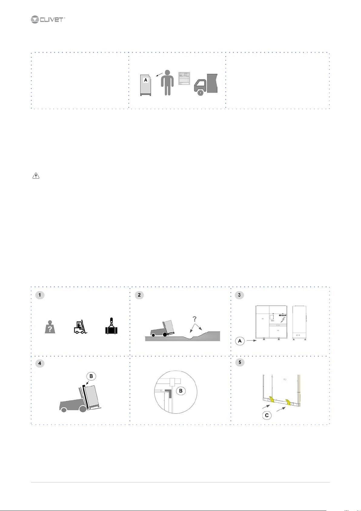
2.2 Handling
Verify unit weight and handling equipment lifting capacity.
•
Identify critical points during handling (disconnected routes, ights, steps, doors).
•
Suitably protect the unit to prevent damage.
•
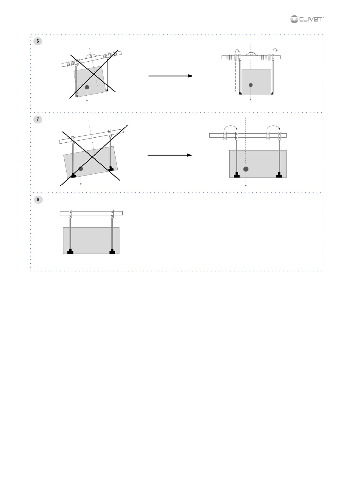
Align the barycenter to the lifting point
•
Use all the lifting brackets (see the dimensional section)
•
Gradually bring the lifting belts under tension, making sure they are positioned correctly.
•
Before starting the handling, make sure that the unit is stable.
•
A Supports for handling: remove after the handling.
B Protections
C Additional lifting brackets
6 WSA-XEE 122-402
M02S40N16-00
Page 7
2.3 Packaging removing
Be careful not to damage the unit.
Keep packing material out of children’s reach it may be dangerous.
Recycle and dispose of the packaging material in conformity with local regulations.
M02S40N16-00 WSA-XEE 122-402 7
Page 8
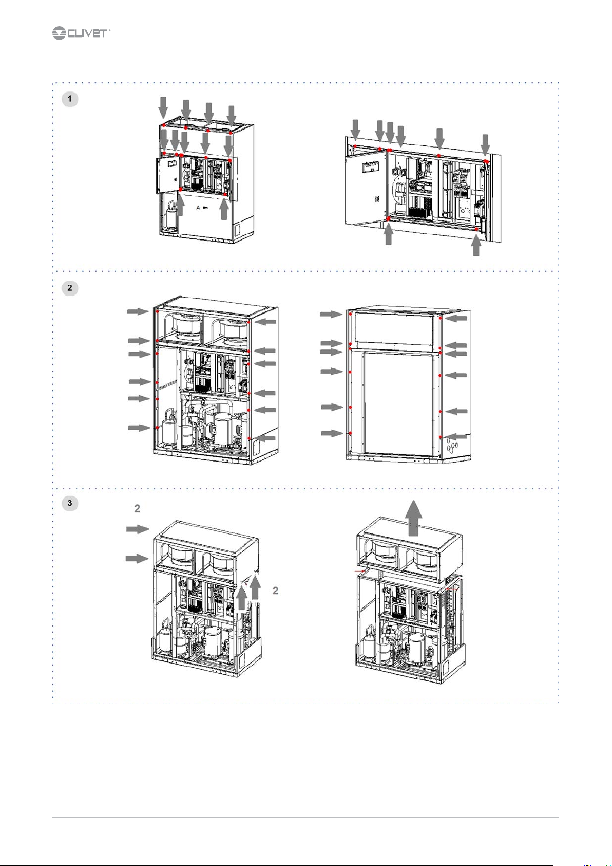
2.4 Removable fan section for shipping
8 WSA-XEE 122-402
M02S40N16-00
Page 9

3 Positioning
During positioning consider these elements:
Technical spaces requested by the unit
•
Electrical connections
•
Water connections
•
Spaces for air exhaust and intake
•
3.1 Functional spaces
Functional spaces are designed to:
guarantee good unit operation
•
carry out maintenance operations
•
protect authorized operators and exposed people
•
Respect all functional spaces indicated in the DIMENSIONS section.
Double all functional spaces if two or more unit are aligned.
3.2 Positioning
Units are designed to be installed:
INTERNAL
•
in xed positions
•
Limit vibration transmission:
use antivibration devices on unit bearing points
•
install exible joints on the hydraulic connections
•
Choose the installation place according to the following criteria:
Customer approval
•
safe accessible position
•
technical spaces requested by the unit
•
spaces for the air intake/exhaust
•
max. distance allowed by the electrical connections
•
Avoid installations in places subject to ooding
•
verify unit weight and bearing point capacity
•
verify that all bearing points are aligned and leveled
•
install the unit raised from the ground
•
A correct circulation of the air is mandatory to guarantee the good unit operating.
Avoid therefore:
obstacles to the airow
•
diculty of exchange
•
leaves or other foreign bodies that can obstruct the air coil
•
winds that hinder or favour the airow
•
heat or pollution sources close to the unit (chimneys, extractors etc..)
•
stratication (cold air that stagnates at the bottom)
•
recirculation (expelled air that is sucked in again)
•
Ignoring the previous indications could:
reduce energy eciency
•
alarm lockout due to HIGH PRESSURE (in summer) or LOW PRESSURE (in winter)
•
3.3 Saftey valve gas side
The installer is responsible for evaluating the opportunity of installing drain tubes, in conformity with the local regulations in force (EN 378).
3.4 Fresh air probe
For details see:
p.
M02S40N16-00 WSA-XEE 122-402 9
Page 10
3.5 Air channelling
When designing and manufacturing the ducting, consider LOAD LOSSES, AIR FLOW AND SPEED that must be consistent with the unit features.
Limit the load losses by optimising the path, the type and number of bends and junctions.
Consider that excessive external static pressure will lead to a reduction in ow rate, with consequent alarm lockout.
Ensure ducts are thermally insulated.
The weight of the ducting must not burden the connection anges.
Place anti-vibration joints between channels and unit.
Connection to the anges and between the various sections of the channels must guarantee air seal, avoiding dispersions penalising the
overall eciency of the system.
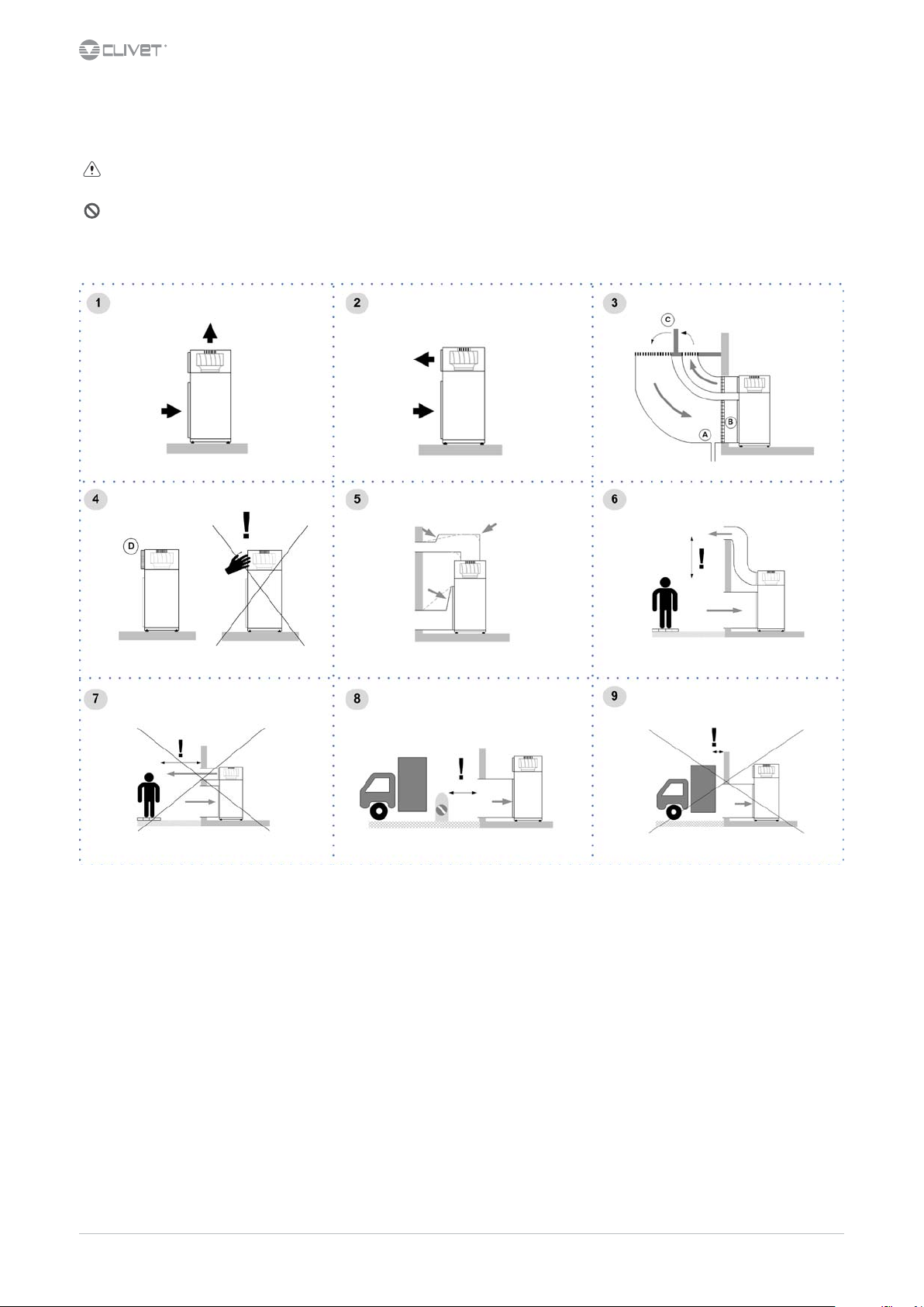
Vertical outlet standard (1)
Rear outlet option (2)
Provide:
water discharge (3-A)
•
grilles to restrict access to small animals (3-B)
•
deectors (3-C) to avoid the by-pass between the two air ows
•
safety grille (4-D)
•
Avoid therefore:
angle curves and narrowings (5)
•
direct air ow on people (6-7), windows, doors, plants, obstacles in general
•
obstacles that prevents the air inow to the coil (8-9)
•
installations next to silent rooms
•
10 WSA-XEE 122-402
M02S40N16-00
Page 11
4 Water connections
4.1 Water quality
Water features
conrming to local regulations
•
total hardness < 14°fr
•
within the limits indicated by table
•
The water quality must be checked by qualied personnel.
Water with inadequate characteristics can cause:
pressure drop increase
•
reduces energy eciency
•
increased corrosion potential
•
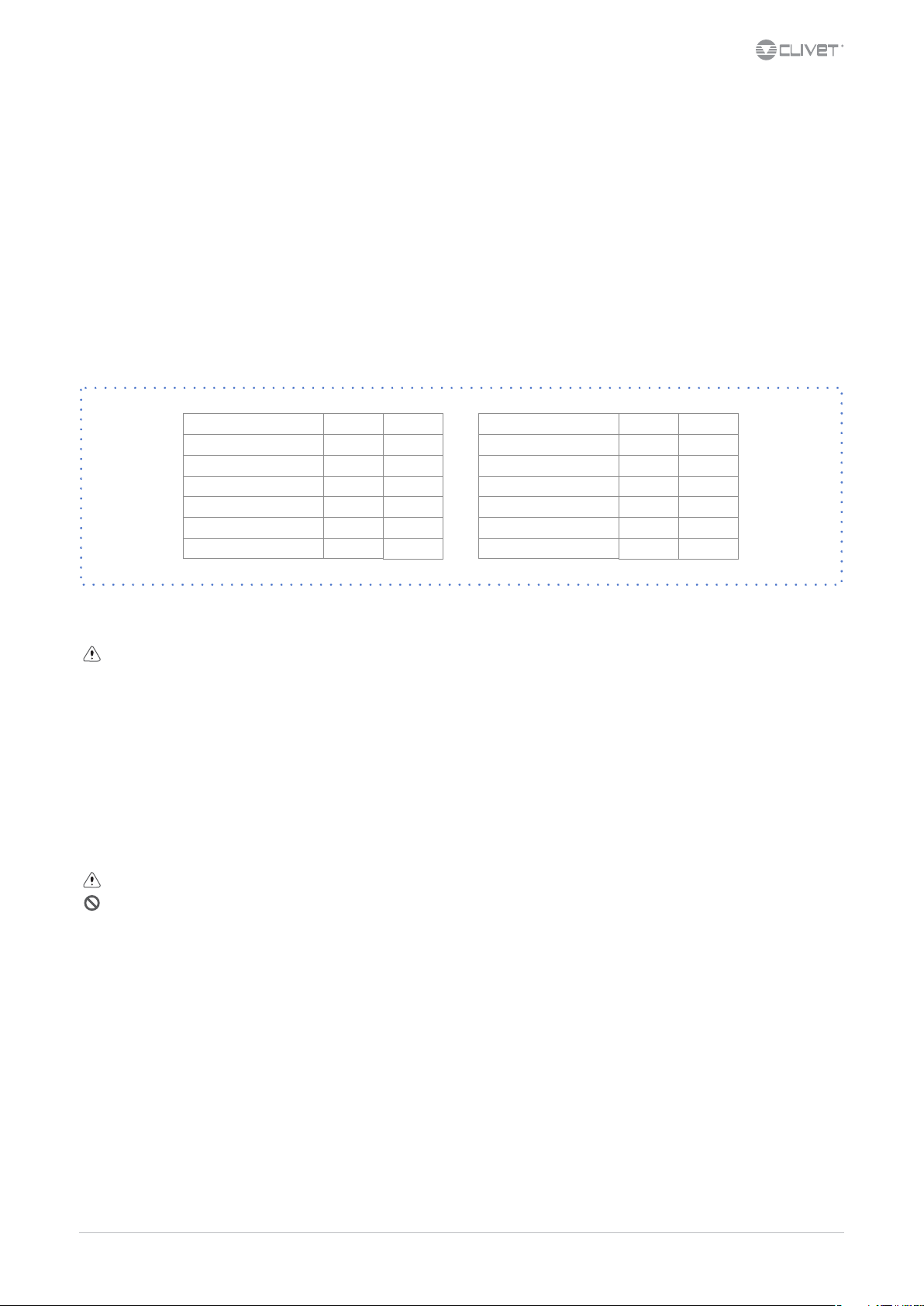
Acceptable water quality values:
PH 7,5 ÷9,0
2-
SO
4
-
HCO
Total Hardness
Cl
PO
NH3 < 0,5
2-
/SO
3
4
-
3-
4
< 100
> 1
4,5 ÷8,5
< 50
< 2,0
ppm
dH
ppm
ppm
ppm
Free Chlorine < 0,5
+
Fe
3
++
Mn
CO
2
H2S
Temperature
Oxygen content < 0,1
< 0,5
< 0,05
< 50
< 50
< 65
ppm
ppm
ppm
ppm
ppb
°C
ppm
Provide a water treatment system if values fall outside the limits.
The warranty does not cover damages caused by limestone formations, deposits and impurities from the water supply and / or failure from
failed system clearing to clean system.
4.2 Risk of freezing
If the unit or the relative water connections are subject to temperatures close to 0°C:
mix water with glycol, or
•
safeguard the pipes with heating cables placed under the insulation, or
•
empty the system in cases of long non-use
•
4.3 Anti-freeze solution
The use of an anti-freeze solution results in an increase in pressure drop.
Make sure that the glycol type utilized is inhibited (not corrosive) and compatible with the water circuit components.
Do not use dierent glicol mixture (i.e. ethylene with propylene).
4.4 Water ow-rate
The project water-ow must be:
inside the exchanger operating limits (see the TECHNICAL INFORMATION section)
•
guarantee, also with variable system conditions (for example in systems where some circuits are bypassed in particular situations).
•
M02S40N16-00 WSA-XEE 122-402 11
Page 12
4.5 Operation sequence
Close all vent valves in the high points of the unit hydraulic circuit
Close all drain valves in the low points of the unit hydraulic circuit:
Heat exchangers
•
Pumps
•
collectors
•
storage tank
•
free-cooling coil
•
1. Carefully wash the system with clean water: ll and drain the system several times.
2. Apply additives to prevent corrosion, fouling, formation of mud and algae.
3. Fill the plant
4. Execute leakage test.
5. Isolate the pipes to avoid heat dispersions and formation of condensate.
6. Leave various point of service free (wells, vent-holes etc).
Neglecting the washing will lead to several lter cleaning interventions and at worst cases can cause damages to the exchangers and the
other parts.
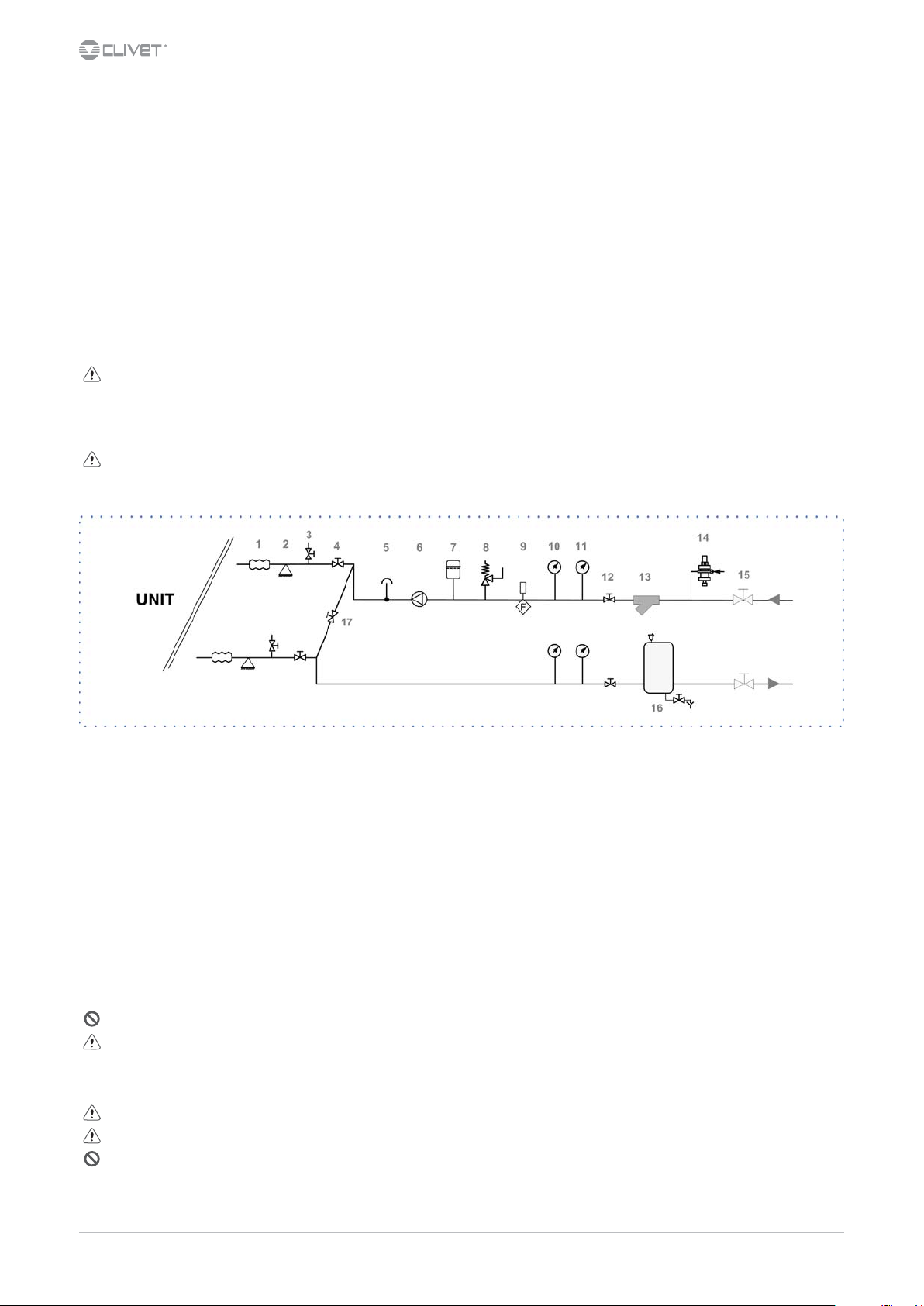
4.6 Recommended connection
The installer must dene:
component type
•
position in system
•
1 antivibration joints 10 pressure gauge
2 piping support 11 thermometer
3 exchanger chemical cleaning bypass 12 shut-o valve
4 shut-o valve 13 lter
5 vent 14 lling valve
6 Pump / circulating pump 15 shut-o valve
7 expansion vessel 16 Internal storage tank
8 safety valve 17 Cleaning system bypass
9 Flow Switch
4.7 Hydraulic connections
take away the supplied connection union by acting on the connection joint
•
weld the union to the installation pipe
•
perform the connection between the installation pipe and the evaporator, using the joint
•
Retirer le joint de connexion avant de souder le tuyau de l’installation.
The rubber gasket might be irreparably damaged.
4.8 Water lter
Use lter with mesh pitch of 1,6 mm
It must be installed immediately in the water input of the unit, in a position that is easily accessible for cleaning.
The lter never should be removed, this operation invalidates the guaranty.
12 WSA-XEE 122-402
M02S40N16-00
Page 13
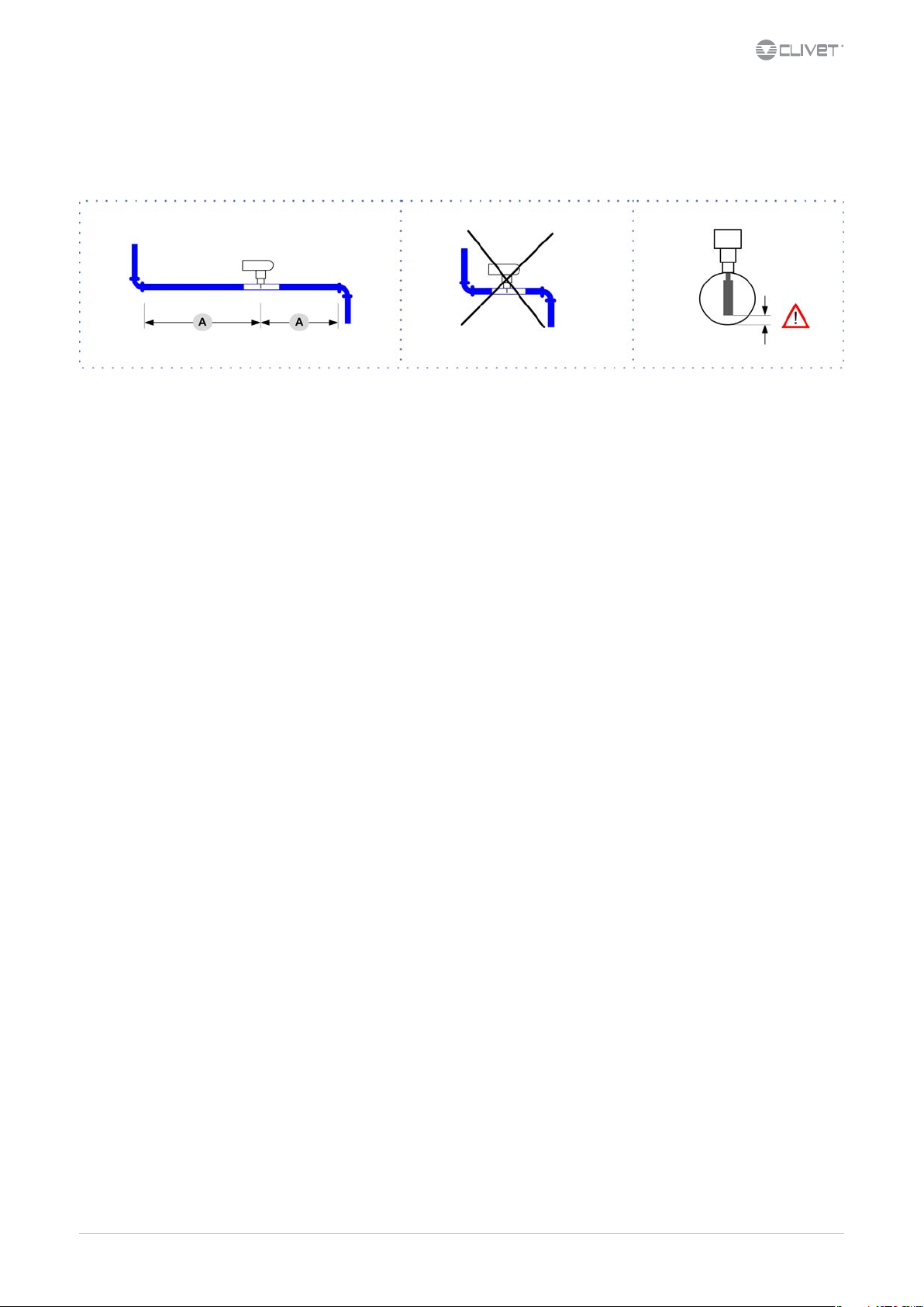
4.9 Flow Switch
The ow switch must be present to ensure shutdown of the unit if water is not circulating.
It has to be installed in a duct rectilinear part, not in proximity of curves that cause turbulences.
A. minimum distance
4.10 Partial energy recovery
For details see:
9.1 Partial energy recoveryp.42
4.11 Single pump
For details see:
p.3
4.12 Couple of manually operated shut-o valves
For details see:
9.3 CSVX - Couple of manually opeated shut-o valvesp.43
M02S40N16-00 WSA-XEE 122-402 13
Page 14

5 Electrical connections
The characteristics of the electrical lines must be determined by qualied electrica personnel able to design electrical installations; moreover,
the lines must be in conformity with regulations in force.
The protection devices of the unit power line must be able to stop all short circuit current, the value must be determined in accordance with
system features.
The power cables and the protection cable section must be dened in accordance with the characteristics of the protections adopted.
All electrical operations should be performed by trained personnel having the necessary qualications required by the regulations in force
and being informed about the risks relevant to these activities.
Operate in compliance with safety regulations in force.
5.1 Electrical data
The serial number label reports the unit specic electrical data, included any electrical accessories.
The electrical data indicated in the technical bulletin and in the manual refer to the standard unit, accessories excluded.
The matriculation plate shows the indications foreseen by the standards, in particular:
Voltage
•
F.L.A.: full load ampere, absorbed current at maximum admitted conditions
•
F.L.I.: full load input, full load power input at max. admissible condition
•
Electrical wiringdiagram Nr.
•
5.2 Connections
1. Refer to the unit electrical diagram (the number of the diagram is shown on the serial number label).
2. Verify that the electrical supply has characteristics conforming to the data shown on the serial number label.
3. Before starting work, ensure the unit is isolated, unable to be turned on and a safety sign used.
4. Ensure correct earth connection.
5. Ensure cables are suitably protected.
6. Before powering up the unit, make sure that all the protections that were removed during the electrical connection work have been
restored.
5.3 Signals / data lines
Do not exceed the maximum power allowed, which varies, according to the type of signal.
Lay the cables far from power cables or cables having a dierent tension and that are able to emit electromagnetic disturbances.
Do not lay the cable near devices which can generate electromagnetic interferences.
Do not lay the cables parallel to other cables, cable crossings are possible, only if laid at 90°.
Connect the screen to the ground, only if there aren’t disturbances.
Guarantee the continuity of the screen during the entire extension of the cable.
Respect impendency, capacity and attenuation indications.
5.4 Power input
Fix the cables: if vacated may be subject to tearing.
The cable must not touch the compressor and the refrigerant piping (they reach high temparatures).
QS1: main isolator switch
XC: Customer connections
5.5 Remote ON-OFF
Do not perform short On O cycles
Do not use the remote On O with thermoregulation function.
YES NO !
A
B
A
A B
A
B
B
14 WSA-XEE 122-402
M02S40N16-00
Page 15
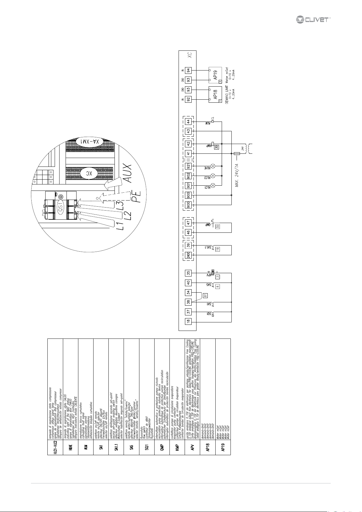
5.6 Connections performer by customer
':*Q6
M02S40N16-00 WSA-XEE 122-402 15
Page 16
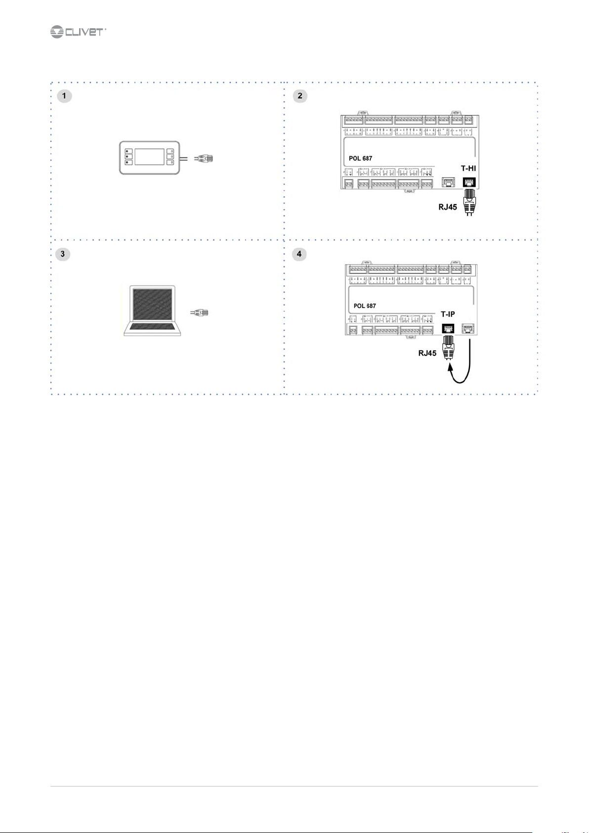
5.7 Computer connection
1. Service keypad
2. RJ45: standard connection
3. P.C.-not supplied
4. P.C. connection, shift RJ45 from T-HI to T-IP
Congure P.C.
1. connect P.C. and main module with LAN cable
2. check in the taskbar that the connection is active
3. open Control Panel and select Network and sharing center
4. select Modify board setting
5. select Local area connection (LAN)
6. select Internet protocol version 4 (TPC) IPV4 and enter Property
7. set the IP address 192.168.1.100
8. set Subnet mask as 255.255.255.0
9. conrm (OK)
10. enter Start (Windows button)
11. write the command cmd and enter/do it
12. write and run the command Ping 192.168.1.42
13. the message, connection is OK, will appear when successful
14. enter the browser (Crhome, Firefox ecc)
15. write and run the command http:/192.168.1.42
16. Userid = WEB
17. Password = SBTAdmin!
16 WSA-XEE 122-402
M02S40N16-00
Page 17
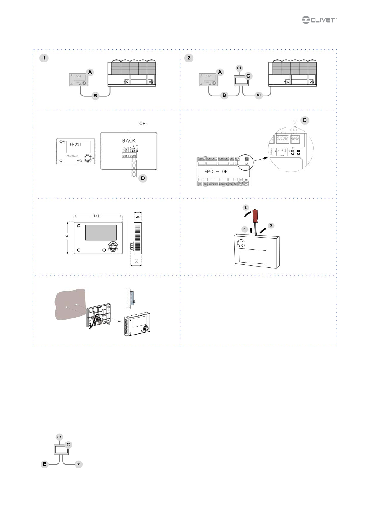
5.8 Remote control
1 Distance up to 350 mt A User interface
2 Distance up to 700 mt B = B1 KNX bus, max 350 mt
C PSX - Mains power supply unit
C1 AC 120...230V, 50...60Hz
D KNX bus, max 350 mt
twisted pair with shield, ø 0,8 mm
EIB/KNX cable marking recommende
pwer supply unit N125/11 5WG1 125-1AB11
5.9 PSX - Mains power supply unit
pwer supply unit N125/11 5WG1 125-1AB11
M02S40N16-00 WSA-XEE 122-402 17
Page 18

5.10 Modbus - RS485
LED BSP communication with AP1 module LED BUS communication with Modbus
green communication ok green communication ok
yellow software ok but communication with AP1
red ashing: software error red communication down
Path
Main menu
down
xed: hardware error
Unit Parameters Modbus
yellow startup / channel not communicating
Parameters Short description Description
P0445: T1 bus termination Termination resistor activation on T1 POL902 [0] port = Passive [1] = Active
P0446: T2 bus termination Termination resistor activation on T2 POL902 [0] port = Passive [1] = Active
A. Unit
B. Metal conduit
C. Metal septums
D. Metal-lined sheath (sleeve)
Modbus / LonWorks / Cable requirements
Couple of conductors twisted and shielded
Section of conductor 0,22mm2…0,35mm2
Rated power between conductors < 50 pF/m
Nominal impedance 120 Ω
Recommended cable BELDEN 3106A
Every RS485 serial line must be set up using the ‘In/Out’ bus system.
•
Other types of networks are not allowed, such as Star or Ring networks.
•
The dierence in potential between the earth of the two RS485 devices that the cable shielding needs to be connected to must be lower
•
than 7 V
There must be suitable arresters to protect the serial lines from the eects of atmospheric discharges
•
A 120 ohm resistance must be located on the end of the serial line. Alternatively, when the last serial board is equipped with an internal
•
terminator, it must be enabled using the specic jumper, dip switch or link.
The cable must have insulation features and non-ame propagation in accordance with applicable regulations.
•
The RS485 serial line must be kept as far away as possible from sources of electromagnetic interference.
•
18 WSA-XEE 122-402
M02S40N16-00
Page 19

5.11 LonWorks
LED BSP communication with AP1 module LED BUS communication with LonWorks
green communication ok green ready for communication
yellow software ok but communication with AP1
down
red ashing: software error red ashing: communicating not possible
xed: hardware error communication down
yellow startup
5.12 BACnet IP
LED BSP communication with AP1 module LED BUS communication with BACnet
green communication ok green ready for communication
yellow software ok but communication with AP1
down
red ashing: software error red BACnet server down
xed: hardware error restart after 3 sec
yellow startup
M02S40N16-00 WSA-XEE 122-402 19
Page 20

6 Start-up
6.1 General description
The indicated operations should be done by qualied technician with specic training on the product.
Upon request, the service centres performing the start-up.
The electrical, water connections and the other system works are by the installer.
Agree upon in advance the star-up data with the service centre.
Before checking, please verify the following:
the unit should be installed properly and in conformity with this manual
•
the electrical power supply line should be isolated at the beginning
•
the unit isolator is open, locked and equipped with the suitable warning
•
make sure no tension is present
•
After turning o the power, wait at least 5 minutes before accessing to the electrical panel or any other electrical component.
Before accessing check with a multimeter that there are no residual stresses.
6.2 Preliminary checks
For details refer to the dierent manual sections.
Unit OFF power supply
1. safety access
2. functional spaces
3. air ow: correct return and supply (no bypass, no stratication)
4. structure integrity
5. fans run freely
6. unit on vibration isolators
7. unit input water lter + shut-o valves for cleaning
8. vibration isolators on water connections
9. expansion tank (indicative volume = 5% system content)
10. Close all drain valves in the low points of the unit hydraulic circuit:
11. cleaned system
12. loaded system + possible glycol solution + corrosion inhibitor
13. system under pressure
14. vented system
15. fresh air probe
16. refrigerant circuit visual check
17. earthing connection
18. power supply features
19. electrical connections provided by the customer
6.3 Start-up sequence
For details refer to the dierent manual sections.
Unit ON power supply
1. compressor crankcase heaters operating at least since 8 hours
2. o-load voltage measure
3. phase sequence check
4. pump manual start-up and ow check
5. shut-o valve refrigerant circuit open
6. unit ON
7. load voltage measure and absorptions
8. liquid sight glass check (no bubbles)
9. check all fan operating
10. measure return and supply water temperature
11. measure super-heating and sub-cooling
12. check no anomalous vibrations are present
13. climatic curve personalization
14. climatic curve personalization
15. scheduling personalization
16. complete and available unit documentation
20 WSA-XEE 122-402
M02S40N16-00
Page 21

6.4 Refrigeration circuit
1. Check carefully the refrigerating circuit: the presence of oil stains can mean leakage caused by transportation, movements or other).
2. Verify that the refrigerating circuit is in pressure: Using the unit manometers, if present, or service manometers.
3. Make sure that all the service outlets are closed with proper caps; if caps are not present a leak of refrigerant can be possible.
4. Open the valves of the refrigerant circuit, if there are any.
6.5 Water circuit
1. Before realizing the unit connection make sure that the hydraulic system has been cleaned up and the cleaning water has been drained.
2. Check that the water circuit has been lled and pressurized.
3. Check that the shut-o valves in the circuit are in the “OPEN” position.
4. Check that there isn’t air in the circuit, if required, evacuate it using the air bleed valve placed in the system high points.
5. When using antifreeze solutions, make sure the glycol percentage is suitable for the type of use envisaged.
Neglecting the washing will lead to several lter cleaning interventions and at worst cases can cause damages to the exchangers and the
other parts.
Weight of glycol (%) 10 20 30 40
Freezing temperature (°C) -3.9 -8.9 -15.6 -23.4
Safety temperature (°C) -1 -4 -10 -19
6.6 Electric Circuit
Verify that the unit is connected to the ground plant.
Check the conductors are tightened as: the vibrations caused by handling and transport might cause these to come loose.
Connect the unit by closing the sectioning device, but leave it on OFF.
Check the voltage and line frequency values which must be within the limits: 400/3/50 +/- 10%
Check and adjust the phase balance as necessary: it must be lower than 2%
Example
Working outside of these limits can cause irreversible damages and voids the warranty.
6.7 Compressor crankcase heaters
Connect the oil resistances on the compressor crankcase at least 8 hours before the compressor is to be starter:
at the rst unit start-up
•
after each prolonged period of inactivity
•
1. Supply the resistances switching o the unit isolator switch.
2. To make sure that heaters are working, check the power input.
3. At start-up the compressor crank-case temperature on the lower side must be higher at least of 10°C than the outside temperature.
Do not start the compressor with the crankcase oil below operating temperature.
6.8 Voltages
Check that the air and water temperatures are within in the operating limits.
Start-up the unit.
With unit operating in stable conditions, check:
Voltage
•
Total absorption of the unit
•
Absorption of the single electric loads
•
M02S40N16-00 WSA-XEE 122-402 21
Page 22

6.9 Remote controls
Check that the remote controls (ON-OFF etc) are connected and, if necessary, enabled with the respective parameters as indicated in the
“electrical connections” section.
Check that probes and optional components are connected and enabled with the respective parameters (“electrical connections” section and
following pages).
6.10 Demand limit
Menu accessible only after having entered the password.
Access reserved only to specically trained personnel.
The parameter modication can cause irreversible damages.
It is possible to limit the absorbed electric power with an external signal 0-10 Vcc or 4-20mA.
The higher the signal is, the lower the number of compressors available to meet the thermal need.
Only if P0050:En DemandLimit ≠ 0
Path: Main Menu / Unit parameters / Demand limit
Step Display Action Menu/Variable Keys Notes
1 Press 3 sec.
2 Password Set Password
3 Press
4 Main menu Select Unit parameters
5 Unit parameters Select Set Point
6 Set Point Select Demand limit
7 Set Demand limit
8 Conrm
9 Press 3 sec.
10 Select Local connections
Path: Main Menu / Unit parameters / Demand limit
Parameters Short description Description
P0009: set demand limit Parameter setting of the value % of demand limit
P0062 TypeDL Inlet signal type: 0=0-10V; 1=4-20mA
22 WSA-XEE 122-402
M02S40N16-00
Page 23

6.11 Climatic TExt
Menu accessible only after having entered the password.
Access reserved only to specically trained personnel.
The parameter modication can cause irreversible damages.
The setpoint dened by the temperature curve is shown at status S0010: ActualSptTExt
Only if P0053: En Climatica ≠ 0
Path: Main Menu / Unit parameters / Climatica TExt
Example
Step Display Action Menu/Variable Keys Notes
1 Press 3 sec.
2 Password Set Password
3 Press
4 Main menu Select Unit parameters
5 Unit parameters Select Climatic TExt
6 Climatic TExt (pwd) Select Parameter
7Set
8 Conrm
9 Press 3 sec.
10 Select Local connections
Path: Main Menu / Unit parameters / Climatica TExt
Parameters Short description Description
P0265: CSptLow setpoint temperature value when the air temperature value is AirAtSptLowC
P0266: AirAtSptLowC external air temperature value where the calculated setpoint takes on the value given by SptLowC
P0267: CSptHigh setpoint temperature value when the air temperature value is AirAtSptHigC
P0268: AirAtSptHigC external air temperature value where the calculated setpoint takes on the value given by SptHigC
M02S40N16-00 WSA-XEE 122-402 23
Page 24

6.12 Water reset
Menu accessible only after having entered the password.
Access reserved only to specically trained personnel.
The parameter modication can cause irreversible damages.
It is possible to limit the absorbed electric power with an external signal 0-10 Vcc or 4-20mA.
The water reset correction aects the setpoint dened by the Climate curve TExt (actual setpoint).
The setpoint is shown at status S0011: ActualSptWR
Only if P0051: En WaterReset ≠ 0
Path: Main Menu / Unit parameters / Water reset
Step Display Action Menu/Variable Keys Notes
1 Press 3 sec.
2 Password Set Password
3 Press
4 Main menu Select Unit parameters
5 Unit parameters Select Water reset
6 Water reset Select Parameter
7Set
8 Conrm
9 Press 3 sec.
10 Select Local connections
Path: Main Menu / Unit parameters / Water reset
Parameters Short description Description
P0063 TypeWR Inlet signal type: 0=0-10V; 1=4-20mA
P0281: MaxCWRC Maximum correction to be applied to the setpoint
P0283: SWRMaxC Value of the WR control signal corresponding to the correction of the set COOL equal to the parameter P0281
P0285 SWRMinC Value of the WR control signal corresponding to the correction of the set COOL equal to 0
24 WSA-XEE 122-402
M02S40N16-00
Page 25

6.13 ECOSHARE function for the automatic management of a group of units
Max 7 units
•
Maximum length of the bus line: 1000 m.
•
Maximum distance between 2 units: 700 m.
•
Type of cable: shielded twisted pair cable Ø 0,8 mm. use an EIB/KNX cable
•
Possible connections: Tree, star, in/out bus, mixed
•
It is not possible to use a ring connection
•
No end-of-line resistor or terminator required
•
There must be suitable arresters to protect the serial lines from the eects of atmospheric discharges
•
The data line must be kept separate from the power conductors or powered at dierent voltage values and away from possible sources
•
of electrical interference
M02S40N16-00 WSA-XEE 122-402 25
Page 26

If there are more units connected in a local network set the mode of operation.
MODE A
Every unit manages its own compressors according to the
setpoint.
Every unit optimizes its refrigeration circuits.
Pumps always active, even with compressor stoped.
P0343 = 0
P0344 > 0 °C
setpoint1 > setpoint2 > setpoint3
or
setpoint1 < setpoint2 < setpoint3
MODE B
The master manages the single cooling.
The master optimizes individual refrigerant circuits.
Pumps always active, even with compressor stoped.
P0343 = 1
P0344 = 0 °C
setpoint1 = setpoint2 = setpoint3
plus: optimal H2O temperature control
MODE C
The master manages the single cooling.
The master optimizes individual refrigerant circuits.
Active pumps only with active compressors.
P0343 = 2
P0344 = 0 °C
setpoint1 = setpoint2 = setpoint3
plus: minimum pumps consumption need balanced system (t1 = t2 = t3)
Path: Main Menu / Unit parameters / Master Slave
Parameters Short description Description
P0340: Address unit ProcessBus address unit
P0341: Unit network Number of network-connected units including the master
P0342: Standby unit Number of units kept in standby
P0343: TypeRegMS Operation mode: 0=mode A; 1=mode B; 2=mode C
P0344: Oset Trm MS
Temperature Oset the master sum or subtract, depending on the way you set, in order of priority, to the set point of
the slave
26 WSA-XEE 122-402
M02S40N16-00
Page 27

6.14 Evaporator water ow-rate
Check that the dierence between the temperature of exchanger return and supply water corresponds to power according to this formula:
unit cooling power (kW) x 860 = Dt (°C) x ow rate (L/h)
The cooling power is shown in the table of the GENERAL TECHNICAL DATA included in this manual, referred to specic conditions, or in the
tables on COOLING PERFORMANCE in the TECHNICAL BULLETIN referred to various conditions of use.
Check for water side exchanger pressure drops:
determine the water ow rate
measure the dierence in pressure between exchanger input and output and compare it with the graph on WATER SIDE EXCHANGER
PRESSURE DROPS
The measurement of pressure will be easier if pressure gauges are installed as indicated in the DIAGRAM OF SUGGESTED WATER CONNECTIONS.
6.15 Operating at reduced load
The units are equipped with partialization steps and they can, therefore, operate with reduced loads.
However a constant and long operation with reduced load with frequent stop and start-up of the compressor/s can cause serious damages
for the lack of oil return.
The above-described operating conditions must be considered outside the operating limits.
In the event of compressor breakdown, due to operating in the above-mentioned conditions, the guarantee will not be valid and Clivet spa
declines any responsibility.
Check periodically the average operating times and the frequency of the compressors starts: approximately the minimum thermal load
should be such as to need the operating of a compressor for at least ten minutes.
If the average times are close to this limit, take the proper corrective actions.
6.16 Scroll compressor
The Scroll compressors have only one rotation direction.
In the event it is reversed, the compressor is not immediately damaged, but increases its noise and jeopardises pumping.
After a few minutes, the compressor blocks due to intervention of the thermal protection.
In this case, disconnect power supply and invert 2 phases on the machine power supply.
Avoid the compressor working for a long time with contrary rotation: more than 2-3 of these anomalous start-ups can damage it.
To ensure the rotation direction is correct, measure the condensation and suction pressure.
The pressures must signicantly dier: upon start-up, the suction pressure decreases whereas the condensation one, increases.
6.17 Start-up report
Identifying the operating objective conditions is useful to control the unit over time.
With unit at steady state, i.e. in stable and close-to-work conditions, identify the following data:
total voltages and absorptions with unit at full load
•
absorptions of the dierent electric loads (compressors, fans, pumps etc)
•
temperatures and ows of the dierent uids (water, air) both in input and in output from the unit
•
temperature and pressures on the characteristic points of the refrigerating circuit (compressor discharge, liquid, intake)
•
The measurements must be kept and made available during maintenance interventions.
6.18 97/23 CE PED directive
97/23 CE PED DIRECTIVE gives instructions for installers, users and maintenance technicians as well.
Refer to local regulations; briey and as an example, see the following:
Compulsory verication of the rst installation:
only for units assembled on the installer’s building site (for ex. Condensing circuit + direct expansion unit)
•
Certication of setting in service:
for all the units
•
Periodical verications:
to be executed with the frequency indicated by the Manufacturer (see the “maintenance inspections” paragraph)
•
M02S40N16-00 WSA-XEE 122-402 27
Page 28

7 Control
7.1 Led
INFO Not used
ALARM Blink / xed = alarm present
CANCEL not used currently
7.2 Display
Ref. Variable Description
A Date - Time
B ActualSetPoint Temperature setting
C T.InH2OUtilitySide Water inlet temperature utility side
D T.OutH2OUtilitySide Water outlet temperature utility side
E ActualState On / o / eco / pmp On
F ActualMode
2 Installed compressors
1 - 0
50% Heating capacity
Cool: water cooling
Heat: Heating (not used)
Compressors ON
example: circuit 1 = 1 compr. On
circuit 2 = 0 compr. On
7.3 Keys
Symbol Name Description
Info Main menu
Alarm Alarm display
Cancel
Exit
Previous level
Keyboard settings
Up Increases value
Down Decreases value
Enter
28 WSA-XEE 122-402
Conrm
Password
M02S40N16-00
Page 29

7.4 Change unit state
Step Display Action Menu/Variable Keys Notes
1 Press
2 Main menu Select Cmd Local state
3 Set OFF - ECO - ON - Pump On *
4 Conrm
6 Exit
* Local state
ECO: recurrent pump ON-OFF; compressors keep water system at setpoint ECO
Pmp ON: pump ON, compressor OFF
7.5 Change the mode
Step Display Action Menu/Variable Keys Notes
1 Press
2 Main menu Select Cmd Local mode
3Set
4 Conrm
5 Exit
Cool: water cooling
Heat: water heating (option)
7.6 Modify setpoint
Step Display Action Menu/Variable Keys Notes
1 Press
2 Main menu Select Unit parameters
3 Unit parameters Conrm Set Point
4 Select Set Point
5 Set Set Point
6 Conrm
7 Exit
Parameters Short description Description
P0001 SetPoint Cool Setpoint Cool
P0002 SetPoint Heat Setpoint Heat Not used
P0003 2°SetPoint Cool 2° Setpoint Cool Enable by remote switch
P0004 2°SetPoint Heat 2° Setpoint Heat not used currently
P0005 SetPoint ECOCool Economic summer SetPoint
P0006 SetPoint ECOHeat Economic winter SetPoint Not used
P0007 SetPointRec Recovery Set Point
M02S40N16-00 WSA-XEE 122-402 29
Page 30

7.7 Scheduler
It is possible to set 6 events (O, Eco, On, Recirculating) for each week day.
Step Display Action Menu/Variable Keys Notes
1 Press
2 Main menu Select Scheduler
3 Scheduler Select Day
4 Select Time
5 Set Event time
6 Conrm
7 Select Value
8 Set On/Eco..
9 Conrm
10 Exit
Enable Scheduler
Step Display Action Menu/Variable Keys Notes
1 Press 3 sec.
2 Password Set Password
3 Press *
4 Main menu Select Unit Parameters
5 Select Option cong
6 Set P0061=1
7 Press 3 sec.
Select Local connections
* Unit Parameters menu is displayed
7.8 Keyboard settings
Step Display Action Menu/Variable Keys Notes
1 Press 3 sec.
2 Press
3 HMI Settings Select
4 Press
5 Press
6 Select Local connections
30 WSA-XEE 122-402
M02S40N16-00
Page 31

7.9 Alarms
Before resetting an alarm identify and remove its cause.
Repeated resets can cause irreversible damage.
Example:
+ eE001: Monitore fase: Fault = active alarm
- EE003: Guasto P1 Util: Ok = resetted alarm
Display of alarm: step 1-3
Reset allarm: step 4-10
Step Display Action Menu/Variable Keys Notes
1 Press
2 Alarm list detail Press
3 Alarm list Select Alarm
4 Alarm list detail Press 3 sec.
5 Password Set Enter password
6 Alarm list detail Press
7 Alarm list Select Alarm
8 Select
9 Press 3 sec.
10 Password management Select Log o
The alarm code identies the concerned circuit:
Example:
ee 1 01:TimeOutModCirc = circuit 1
ee 2 01:TimeOutModCirc = circuit 2
The number of refrigerant circuits depends on series and size of the unit.
Reset
Executed
t.i. input type:
DI = digital input
AI = analogic input
Module:
687 = main module
985 = circuit module
94U = thermostatic driver module
Input:
Connector number:
T1, T2, T3.....
PIN code:
X1, X2, Q13, DO1.....
t.a. alarm type:
A automatic reset
M manual reset
A/M automatic reset, (after N alarm interventions becomes manual reset)
M02S40N16-00 WSA-XEE 122-402 31
Page 32

code detailed description t.i. module input t.a.
eE001 Phase monitor DI 687 central T13 DL1 A/M
EE003 Pump 1 overload DI 687 central T13 DL2 M
EE004 Pump 2 overload DI 687 central T4 D1 M
EE005 Pump 3 overload DI 687 central T13 DL2 M
ee010 Master Oine - Master Slave network enabled A
ee011 Unit 2 in alarm - Master Slave network enabled A
ee012 Unit 2 OLine - Master Slave network enabled A
ee013 Unit 3 in alarm - Master Slave network enabled A
ee014 Unit 3 OLine - Master Slave network enabled A
ee015 Unit 4 in alarm - Master Slave network enabled A
ee016 Unit 4 OLine - Master Slave network enabled A
ee017 Unit 5 in alarm - Master Slave network enabled A
ee018 Unit 5 OLine - Master Slave network enabled A
ee019 Unit 6 in alarm - Master Slave network enabled A
ee020 Unit 6 OLine - Master Slave network enabled A
ee021 Unit 7 in alarm - Master Slave network enabled A
ee022 Unit 7 OLine - Master Slave network enabled A
EE023 Pump 1 thermal protection DI 965 hydronic T1 X4 M
EE024 Pump 2 thermal protection DI 965 hydronic T1 X5 M
EE025 Pump 3 thermal protection DI 965 hydronic T1 X6 A
EE026 Inverter thermal protection DI 965 hydronic T5 DL1 A
ee027 Water inlet temperature probe faulty AI 687 central T1 B1 A
ee028 Water outlet temperature probe faulty AI 687 central T1 B2 A
ee029 External air temperature probe faulty AI 687 central T1 B3 A
ee030 Signal logo or short circuit AI 687 central T2 X1 A
ee031 Signal logo or short circuit AI 687 central T2 X2 A
ee032: External Humidity probe faulty AI 687 central T2 X3 A
ee033: Cabinet temperature probe faulty AI 687 central T2 X4
ee034: Hydronic module on the ProcessBus is disconnected periperal bus A
ee035: Cool opening valve: error limit DI 945 4P X2 A
ee036: Heat opening valve: error limit DI 945 4P X4 A
ee037: Cool closing valve: error limit DI 945 4P X1 A
ee038: Heat closing valve: error limit DI 945 4P X3 A
ee039: Communication timeout 4P module Logico 945 4P periperal bus A
ee040: FCI module water temperature probe fault AI 955 FCI X1 A
ee041: Communication timeout FCI module Logico 955 FCI periperal bus A
EE044: FCI module P1 thermal protection DI 955 FCI X5 M
EE045: FCI module P2 thermal protection DI 955 FCI X6 M
EE046: FCI module P3 thermal protection DI 955 FCI X7 M
ee050: User side exchanger, dierential pressure probe fault 965 hydronic X3 A
ee054: Recovery pump thermal protection DI 955 FCI X6 A
ee101: Circuit 1 module on the ProcessBus is disconnected periperal bus A
ee102: Driver 1 module on the ProcessBus is disconnected periperal bus A
ee103: Recovery 1 module on the ProcessBus is disconnected periperal bus A
ee104: Driver 1 blocked 94U driver A
EE106: Compressor 1 thermal protection DI 985 circuit 1 T4 D1 M
EE107: Compressor 2 thermal protection DI 985 circuit 1 T4 D2 M
EE108: Compressor 3 thermal protection DI 985 circuit 1 T4 D3 M
EE118: Source side protection DI 985 circuit 1 T9 DL2 M
ee122: Faulty probe - discharge temperature compressor 1 AI 985 circuit 1 T1 B1 A
ee123: Faulty probe - discharge temperature compressor 2 AI 985 circuit 1 T1 B2 A
ee124: Faulty probe - discharge temperature compressor 3 AI 985 circuit 1 T2 X2 A
ee125: Faulty probe - source 1 temperature AI 985 circuit 1 T1 B3 A
A
32 WSA-XEE 122-402
M02S40N16-00
Page 33

code detailed description t.i. module input t.a.
ee126: Faulty probe - source 2 temperature AI 985 circuit 1 T2 X1 A
ee127: Faulty probe - Suction temperature AI 94U driver T2 X2 A
ee128: Faulty probe - discharge pressure AI 985 circuit 1 T2 X3 A
ee129: Faulty probe - suction pressure AI 94U driver T1 X1 A
ee130: Faulty probe - Recovery gas temperature AI 965 recovery T1 X1 A
ee131: Faulty probe - Recovery pressure AI 965 recovery T2 X7 A
ee132: Faulty probe - Water recovery inlet AI 965 recovery T1 X2 A
ee133: Faulty probe - Water recovery outlet AI 965 recovery T1 X3 A
ee135: Bios wrong version 985 circuit 1 A
105: Low overheating Thermostatic C1 A
fF109: Low pressure from analogic input DI 985 circuit 1 T3 X7 A/M
110: Pre-alarm - low pressure COOL mode A
111: Pre-alarm - low pressure HEAT mode A
fF112: Low pressure from analogic input AI 94U driver T1 X1 A/M
fF113: High pressure from digital input DI 985 circuit 1 T3 X8 A/M
114: Pre-alarm - high pressure A
fF115: High pressure from analogic input AI 985 circuit 1 T2 X3 A/M
116: Pre-alarm max. compression ratio (high pressure / low pressure) A
fF117: Min. compression ratio (high pressure / low pressure) A/M
FF119: Alarm max. compression ratio (high pressure / low pressure) M
FF134 Empty circuit AI 94U driver T1 X1 M
136: Defrost: low gas temperature Logico 985 X2 M
fF137: Oil pressure DI 985 DL1 A/M
138: Low condensing pressure Logico 985 X3 A
fF139: Maximum saturated condensation temperature Logico A/M
fF140: Minimum saturated condensation temperature Logico
A/M
fF141: Maximum saturated evaporation temperatur Logico A/M
fF142: Minimum saturated evaporation temperatur Logico A/M
fF143: Maximum compression ratio Logico A/M
FF144: Minimum compression ratio Logico M
fF145: Maximum engine torque Logico A/M
iI002: Low water pressure DI 687 central T5 DU1 A/M
iI006: Flow switch utility side DI 687 central T3 X8 A/M
II007: Freeze alarm utility side M
ii008: Utility side pumps On for antifreeze alarm A
COOL:
outlet temperature higher than inlet temperature
II009:
HEAT:
inlet temperature higher than outlet temperature
iI120: Flow switch source side DI 985 circuit 1 T2 X4 A/M
II121: Freeze alarm source side A
II042: FCI module, system pressure DI 955 FCI X3 M
II043: FCI module, antifreeze alarm Logico 955 FCI X1 M
ii047: FCI module, water ow alarm DI 955 FCI X4 A
ii052: Recosery module, ow alarm DI 965 REC X6 A
ii053: Recovery module, system pressure DI 965 REC X6 A
A
M02S40N16-00 WSA-XEE 122-402 33
Page 34

7.10 Display the status
Step Display Action Menu/Variable Keys Notes
1 Press
2 Main menu Select Machine State
3 Select General, circuit, ecc..
4 Exit
7.11 General stata and central module
code description detailed description
AI-687 T.IN H2OUtil_B1 Inlet water temperature utility side
AI-687 T.OUT H2OUtil_B2 Outlet water temperature user side
AI-687 Ext.Air temp_B3 Outdoor air temperature
AI-687 S.DemandLimit_X1 Signal of the demand limit function controls
AI-687 S.WaterReset_X2 Signal of the water reset function controls
AI-687 RHExt_X3 Outside relative humidity
AI-687 El.CabinetTemp_X4 Electrical panel temperature
AO-687 %FREE-COOLING _X5 Percentage value of the status of the external control signal of the ventilation/FREE-COOLING valve
DI-687 Sel.SetPoint_DU2 Status of the second digital input setpoint 0=1°set 1=2°Set
DI-687 SystemPressure_DU1 Status of the system water pressure sensor 0=OK 1=Fault
DI-687 FlowUser_X8 Status of the dierential pressure switch/utilisation ow 0=OK 1=Fault
DI-687 ON-OFFRem_X7 Status of the unit status digital input 0=OFF 1=On
DI-687 Heat/CoolRem_X6 Status of the unit mode digital input 0=Heat 1=Cool
DI-687 PhaseMonitor_DL1 Status of the phase monitor input 0=OK 1=Fault
DI-687 OvlP1Util_D2 Status of thermal protection contact of utilisation pump 1 0=OK 1=Fault
DI-687 OvlP2Util_D1 Status of thermal protection contact of utilisation pump 2 0=OK 1=Fault
DI-687 OvlP3Util_DL2 Status of thermal protection contact of utilisation pump 3 0=OK 1=Fault
DO-687 El.CabinetFAN_DO1 Status of the ventilation control of the electrical panel: 0=O 1=On
DO-687 El.CabinetHEAT_DO2 Status of the heating control of the electrical panel: 0=O 1=On
DO-687 UnitMode_Q1 Status of the digital output related to the operating mode (N.O. Open=Cool N.O. Closed=Heat): 0=Cool 1=Heat
DO-687 Cumul.Alarm_Q2 Unit cumulative alarm status (N.0.Open=All OFF N.O. Closed=All ON): 0=O 1=On
DO-687 CmdP1User_Q3 Command pump 1 utility side: 0=O 1=On
DO-687 CmdP2User_Q4 Command pump 2 utility side: 0=O 1=On
DO-687 CmdP3User_Q5 Command pump 3 utility side: 0=O 1=On
DO-687 OpenYV FC_Q7 Opening control of the FREE-COOLING valve FC Closed = ON: 0=O 1=On
DO-687 CloseYV FC_Q8 Closure control of the FREE-COOLING valve FC Closed = OFF: 0=O 1=On
DO-687 AntifreezeHeater_Q6 Status of the control of the antifreeze heaters: 0=O 1=On
S0001 StartsP1User Number of startup totalized from Pump 1
S0002 StartsP2User Number of startup totalized from Pump 2
S0003 StartsP3User Number of startup totalized from Pump 3
S0004 Pump1 running hours Utilisation pump 1 hours
S0005 Pump2 running hours Utilisation pump 2 hours
S0006 Pump3 running hours Utilisation pump 3 hours
S0007 Antifreeze heat. Antifreeze heater status 0=O 1=On
S0008 Pump in antifreeze Status of the utilisation pump for antifreeze protection 0=O 1=On
S0009 Recovery Recovery status: 0=O 1=On
S0010 ActualSptTExt Setpoint value calculated by the Text climate curve
S0011 ActualSptWR Setpoint value calculated by the WaterReset function
S0012 StatusFREE-COOLING FREE-COOLING status 0=O 1=On
S0013 GenWarning 0=O 1=On
S0014 GenBlock 0=O 1=On
S0015 NCompOnUnit Number of compressors currently active on the machine
34 WSA-XEE 122-402
M02S40N16-00
Page 35

7.12 Circuit 1 status
code description detailed description
AI-94U SuctionTemp_X2 Suction temperature
AI-94U SuctionPressureX1 Low pressure transducer
AI-985 DischargeTC1_B1 Compressor 1 discharge temperature
AI-985 DischargeTC2_B2 Compressor 2 discharge temperature
AI-985 DischargeTC3_X2 Compressor 3 discharge temperature
AI-985 SourceTemp1_B3
AI-985 SourceTemp2_X1
AI-985 DischargePressure_X3 High pressure transducer
AO-985 %Cmd Cmp_X5 Percentage value of the status of the control signal of the modulating compressor
AO-985 %Cmd Source_X6 % value source modulating signal control
DI-985 Source WaterFlow_X4 Status of the source ow contact (Only active on machines with water-based source): 0=Fault 1=OK
DI-985 LP Pressure switch_X7 Status of the LP-pressure switch contact: 0=Fault 1=OK
DI-985 Ovl Inverter_DL1 Status of the inverter compressor heater contact: 0=Fault 1=OK
DI-985 HP Pressure switch_X8 Status of the HP-pressure switch contact: 0=Fault 1=OK
DI-985 Ovl Source_DL2 Status of the contact of the thermal protection of the source motors: 0=Fault 1=OK
DI-985 Ovl Cmp1_D1 Status of the contact of the thermal protection of compressor 1: 0=Fault 1=OK
DI-985 Ovl Cmp2_D2 Status of the contact of the thermal protection of compressor 2: 0=Fault 1=OK
DI-985 Ovl Cmp3_D3 Status of the contact of the thermal protection of compressor 3: 0=Fault 1=OK
DI-985
DI-985 EnCircScrew_D3 Status of the circuit enabling input contact (Active if compressor = Screw): 0=Fault 1=OK
DO-985 Cmd Cmp1_Q2 Status of the compressor 1 control: 0=O 1=On
DO-985 Cmd Cmp2_Q3 Status of the compressor 2 control: 0=O 1=On
DO-985 Cmd Cmp3_Q4 Status of the compressor 3 control: 0=O 1=On
DO-985 Cmd Source_Q1 Status of the source motor control: 0=O 1=On
DO-985 Cmd Inj.Cmp1_Q5 Status of the compressor 1 liquid injection valve control: 0=O 1=On
DO-985 Cmd Inj.Cmp2_Q7 Status of the compressor 2 liquid injection valve control: 0=O 1=On
DO-985 Cmd Inj.Cmp3_Q8 Status of the compressor 3 liquid injection valve control: 0=O 1=On
DO-985
DO-985 Cmd Digital_DO2 Status of the button valve control for compressors PWM: 0=O 1=On
DO-985 Cmd KMLine_Q2 Status of the line counter control for the power supply Cmp (Active if compressor = Screw): 0=O 1=On
DO-985 Cmd KMPW1_Q3
DO-985 Cmd KMPW2_Q4
DO-985 Cmd YV25%_Q7 Status of the start e stop valve YV25%(Active if compressor = Screw): 0=O 1=On
DO-985 Cmd YV75%_Q8 Status of the valve control of the YV75%(CR3_Bitzer) (14_Refcomp) (Active if compressor = Screw): 0=O 1=On
DO-985 Cmd YVUP_DO1 Status of the power increase valve control (CR4_Bitzer) (16_RefComp) (Active if compressor = Screw): 0=O 1=On
DO-985 Cmd YVDW_DO2 Status of the power decrease valve control (CR2_Bitzer) (15_RefComp) (Active if compressor = Screw): 0=O 1=On
S1100 CMP1 starts Number of startup totalized from Compressor 1
S1101 CMP2 starts Number of startup totalized from Compressor 2
S1102 CMP3 starts Number of startup totalized from Compressor 3
S1103 StartsScrew Number of startup totalized from Compressor
S1104 Source starts Number of startup totalized from source Fan or pump
S1105
S1106 Hours Comp.2 Compressor 2 hours
S1107 Hours Comp.3 Compressor 3 hours
S1108 HoursScrew Screw compressor hours
S1109 HoursSource Screw compressor hours
S1110 Total steps Total number of active steps on the circuit
S1111 Comp.1 status Compressor 1: 0=free 1=on 2=timing 3=Disabled
S1112 Comp.2 status Compressor 2: 0=free 1=on 2=timing 3=Disabled
Di.PressureOilScrew_
D2
Cmd YV4 reversingValve_Q6
Hours Comp.1 Compressor 1 hours
Source 1 temperature (for machines with air-based sources and reversible on gas = Probe 1 on source battery.
For machines with water-based source = Source input probe)
Source 2 temperature (for machines with air-based sources and reversible on gas = Probe 2 on source battery.
For machines with water-based source = Source outlet probe)
Status of the oil dierential pressure switch contact (Active if compressor = Screw): 0=Fault 1=OK
Status of the cycle inversion valve control: 0=O 1=On
Status of the control of the motor’s 1st winding (with PartWiding start-up) / Status of the star contactor control (with delta
start-up)(Active if compressor = Screw): 0=O 1=On
Status of the control of the motor’s 2nd winding (with PartWiding start-up) / Status of the control of the triangle contactor
(with delta start-up)(Active if compressor = Screw): 0=O 1=On
M02S40N16-00 WSA-XEE 122-402 35
Page 36
code description detailed description
S1113 Comp.3 status Compressor 3: 0=free 1=on 2=timing 3=Disabled
S1114 Current cap. Capacity currently used up on the circuit
S1115 Requested cap. Capacity required on the circuit
S1116 Pressure ratio Compression ratio status (1+HP/1+LP)
S1117 FANPreAlarm Status of the current maximum ventilation pre-alarm 0=O 1=On
S1118 Defrost delay
S1119 Defrosting status
S1120 HWErr
S1121 BlckingHWErr
S1122 FailSafeSta Active block status: 0=O 1=On
S1123 UPSNotAval UPS failure: 0=O 1=On
S1124 CircWarning Status associated with circuit block alarm
S1125 CircBlock Lock alarm circuit
S1126 ThTDischarge Theoretical discharge temperature
Current value of the countdown towards the cycle inversion due to defrosting. (defrosting starts when the value reaches
zero)
Indicates the defrosting status 0=DfrO (Cycle inversion phase for defrosting phase NOT active) 1=DfrON (Cycle inversion
phase for defrosting phase ACTIVE)
Hardware error of the POL94U module that does not preclude the possibility of moving the valve or closing it.
Possible causes: anomalous voltage values in the valve motor 0=O 1=On
Hardware error of the POL94U module that prevents the electronic valve from moving.
Possible causes: UPS not available, wrong POL94U Bios, HW POL94U Error, Disconnected EEV Motor, calibration error associated with conguration parameters. 0=O 1=On
7.13 Thermostatic C1 status
code description detailed description
S1200 SHSpOp Operating overheating setpoint net with SH and MET adjustments
S1201 AICalSuctSprHtP Actual Overheating SetPoint
S1202 ECVState 0 = Idle 1 = ECVAlarm 2 = FailSafe 3 = Referencing 4 = Positioning 5 = Positioned 6 = ECVWaiting 7 = FastClosing
S1203 EEV:SH_Limiter Maximum valve opening determined by the minimum SH control function
S1204 EEV:LET_Limiter Status of the minimum LET intake temperature control
S1205 EEVMode
S1206 Prepos Thermostatic requested positioning %
S1207 ECVSetPos % Opening valve if EEVMod = Manual
S1208 ECVMode 0 = Idle 1 = Init 2 = Position 3 = FastClose
S1209 SHPIDOut % value of the PID output to adjust the valve
S1210 EEVStatus
S1211 SetPosSteps Control of the number of steps the valve must reach to adjust overheating
S1212 SetPos% Opening % control of the valve to adjust overheating
S1213 Pol94xCommOK Connection status of the POL94U module on processbus: 0=NotOK 1=OK
S1214 ActPos% % value of the actual position valve EEV
S1215 ActPosSteps Current number of steps of the EEV valve
S1216 ECVMode 0 = Idle 1 = Init 2 = Position 3 = FastClose
S1217 ECVState 0 = Idle 1 = ECVAlarm 2 = FailSafe 3 = Referencing 4 = Positioning 5 = Positioned 6 = ECVWaiting 7 = FastClosing
0=Idle (motor o) 1=Init (valve initialised when completely closed) 2=Manual (valve controlled in manual mode) 3=Control
(the valve conducts adjustments to control SH)
0 - Closed (Ready) 1 - StartUpPositioning 2 - StartUpPositioned 3 - SuperHeat 4 - Prepositioning 5 - MET 6 - LET 7 - Closing 8 PumpDown 9 - DangAlarm 10 - PumpDownStartUp 11 - ECVAlarm 12 - MinSHLmtr 13 - WaitValveClose 255 - Warning
7.14 Recovery circuit 1 status
code description detailed description
AI-965 P.OutRec_X7 Pressure value recovery circuit
AI-965 T.InH2ORec_X2 Recovery inlet water temperature
AI-965 T.OutH2ORec_X3 Recovery outlet water temperature
AI-965 T.OutGasRec_X1 Recovery gas outlet temperature (liquid)
AO-965 %CmdPmpRec_X8 % 0-10vcc signal value recovery variable pump
DI-965 EnableRec_X4 Enabling recosvery input: 0=Fault 1=OK
DI-965 Ovl PmpRec_X5 Recovey thermal protection pump 0=Fault 1=OK
DI-965 FlowRec_X6 Flow recovery 0=Fault 1=OK
DI-965
36 WSA-XEE 122-402
SystemPress.Recovery_DL1
State of the water pressure switch contact of the system 0=Fault 1=OK
M02S40N16-00
Page 37

code description detailed description
DO-965 YV1Rec_DO1 Command valve YV1 0=O 1=On
DO-965 YV2Rec_DO2 Command valve YV2 0=O 1=On
DO-965 YV3Rec_Q1 Command valve YV3 0=O 1=On
DO-965 YV4Rec_Q2 Command valve YV4 0=O 1=On
DO-965 YV5Rec_Q3 Command valve YV5 0=O 1=On
DO-965 PmpRec_Q4 Recovery pump command 0=O 1=On
7.15 Master slave status
code description detailed description
S0600 SetPoint Unit1
S0601 SetPoint Unit2
S0602 SetPoint Unit3
S0603 SetPoint Unit4
S0604 SetPoint Unit5
S0605 SetPoint Unit6
S0606 SetPoint Unit7
S0607 statusUnit1
S0608 StatusUnit2
S0609 StatusUnit3
S0610 StatusUnit4
S0611 StatusUnit5
S0612 StatusUnit6
S0613 StatusUnit7
Value accessible from the display of the unit machine network master.
Working setpoint master unit (Address 1 on periferalbus)
Value accessible from the display of the unit machine network master.
Working setpoint unit 2 (Address 2 on periferalbus)
Value accessible from the display of the unit machine network master.
Working setpoint unit 3 (Address 3 on periferalbus)
Value accessible from the display of the unit machine network master.
Working setpoint unit 4 (Address 4 on periferalbus)
Value accessible from the display of the unit machine network master.
Working setpoint unit 5 (Address 5 on periferalbus)
Value accessible from the display of the unit machine network master.
Working setpoint unit 6 (Address 6 on periferalbus)
Value accessible from the display of the unit machine network master.
Working setpoint unit 7 (Address 7 on periferalbus)
Value accessible from the display of the unit machine network master.
Status master unit 7 0=O 1=Eco 2=On 3=PmpOn
Value accessible from the display of the unit machine network master.
Status unit 2 0=O 1=Eco 2=On 3=PmpOn
Value accessible from the display of the unit machine network master.
Status unit 3 0=O 1=Eco 2=On 3=PmpOn
Value accessible from the display of the unit machine network master.
Status unit 4 0=O 1=Eco 2=On 3=PmpOn
Value accessible from the display of the unit machine network master.
Status unit 5 0=O 1=Eco 2=On 3=PmpOn
Value accessible from the display of the unit machine network master.
Status unit 6 0=O 1=Eco 2=On 3=PmpOn
Value accessible from the display of the unit machine network master.
Status unit 7 0=O 1=Eco 2=On 3=PmpOn
7.16 Hydronic module status
code description detailed description
AO-965 %CmdInverter_X7 % value inverter command signal
DI-965 OvlP1.Hid_X4 Pump 1 overload 1: 0=OK 1=Fault
DI-965 OvlP2.Hid_X5 Pump 2 overload: 0=OK 1=Fault
DI-965 OvlP3.Hid_X6 Pump 3 overload: 0=OK 1=Fault
DI-965 OvlInv.Hid_DL1 Inverter overload: 0=OK 1=Fault
DO-965 CmdP1.Hid_DO1 Pump 1 command: 0=O 1=On
DO-965 CmdP1Inv.Hid_Q2 Pump 1 inverter command: 0=O 1=On
DO-965 CmdP2.Hid_DO2 Pump 2 command: 0=O 1=On
DO-965 CmdP2Inv.Hid_Q3 Pump 2 inverter command: 0=O 1=On
DO-965 CmdP3.Hid_Q1 Pump 3 command: 0=O 1=On
DO-965 ComdP3Inv.Hid_Q4 Pump 3 inverter command: 0=O 1=On
DO-965 CmdInverter:X8 Hydronic inverter command: 0=O 1=On
S0500 StartsP1Hidro Hydronic module pump 1 starts
S0501 StartsP2Hidro Hydronic module pump 2 starts
S0502 StartsP3Hidro Hydronic module pump 3 starts
S0503 HoursP1.Hid Hydronic module pump 1 hours
S0504 HoursP32.Hid Hydronic module pump 2 hours
M02S40N16-00 WSA-XEE 122-402 37
Page 38

code description detailed description
S0505 HoursP3.Hid Hydronic module pump 3 hours
S0506 HoursInverter.Hid Hydronic module inverter hours
7.17 Energy meter status
code description detailed description
S0720 U12 L1 - L2 voltage
S0721 U23 L2 - L3 voltage
S0722 U31 L3 - L1 voltage
S0723 Freq Frequency
S0724 IL1 L1 current
S0725 IL2 L2 current
S0726 IL3 L3 current
S0727 Ptotale Current active power
S0728 Cos Total power factor
S0729 Energy Active energy totalized
S0730 THD-U12 Sum of harmonic components of voltage between L1 e L2
S0731 THD-U23 Sum of harmonic components of voltage between L2 e L3
S0732 THD-U31 Sum of harmonic components of voltage between L3 e L1
38 WSA-XEE 122-402
M02S40N16-00
Page 39

8 Maintenance
8.1 General description
Maintenance must be done by authorized centres or by qualied personnel.
The maintenance allows to:
maintain the unit eciency
•
increase the life span of the equipment
•
assemble information and data to understand the state of the unit eciency and avoid possible damages
•
Before checking, please verify the following:
the electrical power supply line should be isolated at the beginning
•
the unit isolator is open, locked and equipped with the suitable warning
•
make sure no tension is present
•
After turning o the power, wait at least 5 minutes before accessing to the electrical panel or any other electrical component.
Before accessing check with a multimeter that there are no residual stresses.
8.2 Inspections frequency
Perform an inspection every 6 months minimum.
The frequency, however, depends on the use.
In the event of frequent use it is recommended to plan inspections at shorter intervals:
frequent use (continuous or very intermittent use, near the operating limits, etc)
•
critical use (service necessary)
•
√ intervention frequency (months) 1612
1 presence corrosion X
2 panel xing X
3 fan xing X
4 coil cleaning X
5 water lter cleaning X
6 check the exchanger eciency X
7 circulating pumps X
8 check of the xing and the insulation of the power lead X
9 check of the earthing cable X
10 electric panel cleaning X
11 capacity contactor status X
12 termina closing, cable insulation integrity X
13 voltage and phase unbalancing (no load and on-load) X
14 absorptions of the single electrical loads X
15 test of the compressor crankcase heaters X
16 leak control* X
17 survey of the refrigerant circuit operating parameters X
18 protective device test: pressure switches, thermostats, ow switches etc.. X
19 Safety valves: refer to the local regulations
20 control system test: setpoint, climatic compensations, capacity stepping, water / air ow-rate variations X
21 control device test: alarm signalling, thermometers, probes, pressure gauges etc.. X
* European regulation 303/2008
Refer to the local regulations; and ensure correct adherance. Companies and technicians that eect interventions of installation, maintenance/
repairs, leak control and recovery must be CERTIFIED as expected by the local regulations. The leak control must be eected with annual
renewal.
8.3 Unit booklet
It’s advisable to create a unit booklet to take notes of the unit interventions.
In this way it will be easier to adequately note the various interventions and aid any troubleshooting.
Report on the booklet:
date
•
type of intervention eected
•
intervention description
•
carried out measures etc.
•
M02S40N16-00 WSA-XEE 122-402 39
Page 40

8.4 Standby mode
If a long period of inactivity is foreseen:
turn o the power
•
avoid the risk of frost (empty the system or add glycol)
•
Turn o the power to avoid electrical risks or damages by lightning strikes.
With lower temperatures keep heaters turned on in of the electrical panel (option).
It’s recommended that the re-start after the stopping period is performed by a qualied technician, especially after seasonal stops or seasonal
switching.
When restarting, refer to what is indicated in the “start-up” section.
Schedule technical assistance in advance to avoid hitches and to guarantee that the system can be used when required.
8.5 Water side exchanger
It is very important for the exchanger to be able to provide the maximum thermal exchange, therefore it is essential for the inner surfaces to
be clean of dirt and incrustations.
Periodically check the dierence between the temperature of the supply water and the condensation temperature: if the dierence is greater
than 8°C–10°C it is advisable to clean the exchanger.
The clearing must be eected:
with circulation opposite to the usual one
•
with a speed at least 1,5 times higher than the nominal one
•
with an appropriate product moderately acid (95% water + 5% phosphoric acid)
•
after the cleaning rinse with water to inhibit the action of any residual product
•
8.6 Water lter
Check that no impurities prevent the correct passage of water.
8.7 Circulating pumps
Check:
no leaks
•
bearing status (anomalies are highlighted by abnormal noise and vibration)
•
the terminal protection covers are closed and the cable holders are properly positioned
•
8.8 Flow Switch
controls the operations
•
remove incrustations from the palette
•
8.9 Electric fans
Check:
the fans and the relative protection gridsare well xed
•
the fan bearings (evident by noise and anomalous vibrations)
•
the terminal protection covers are closed and the cable holders are properly positioned
•
8.10 Air coil
Contact with the exchanger ns can cause cuts: wear protective gloves to perform the above described operations.
It is extremely important that the battery gives the maximum thermal exchange; therefore, its surface must be cleaned from dust and deposits.
Remove all impurities from the surface.
Using an air pressure gun, clean the aluminum surface of the battery; be careful to direct the air in the opposite direction of the fan air
movement.
Hold the gun parallel to the ns to avoid damages.
As an alternative, vacumn cleaner can be used to suck impurities from the air input side.
Verify that the aluminum ns are not bent or damaged, in the event of damages contact the authorized assistance center and get the ns
straightened in order to restore the initial condition for an optimal air ow.
40 WSA-XEE 122-402
M02S40N16-00
Page 41

8.11 Compressor supply line shut-o valve
A. Supply line shut-o valve
Do not remove the seal
Remove only if authorized by the manufacturer.
Please contact the maker for informations.
8.12 crankcase heather
Check:
closure
•
Operation
•
8.13 System discharge
1. evacuate the system
2. evacuate the exchanger, use all the cocks presents
3. use compressed air to blow the exchanger
4. dry completely the exchanger by an hot air jet; for greater safety ll the exchanger with glycoled solution
5. protect the exchanger from the air
6. remove the drain plugs to the pumps
Any anti-freeze liquid contained in the system should not be discharged freely as it is a pollutant.
It must be collected and reused.
Before starting a washing the plant.
Example
emptying pump
•
It’s recommended that the re-start after the stopping period is performed by a qualied technician, especially after seasonal stops or seasonal
switching.
When restarting, refer to what is indicated in the “start-up” section.
Schedule technical assistance in advance to avoid hitches and to guarantee that the system can be used when required.
M02S40N16-00 WSA-XEE 122-402 41
Page 42

9 Accessories
9.1 Partial energy recovery
A conguration which enables the production of hot water free-of-charge while operating in the cooling mode, thanks to the partial recovery
of condensation heat that would otherwise be rejected to the external heat source.
The maximum capacity available from the partial recovery is equal to the 15% of the rejected heating capacity (cooling capacity + compressor
power input)
The recovery exchanger must be always maintained full of water
The lack of water amplies the noise generated by the operation
When the temperature of the water to be heated is particularly low, it is wise to insert a ow-rate control valve into the system water circuit,
in order to maintain the temperature at the recovery output at above 35°C and thus avoid the condensation of the refrigerant into the partial
energy recovery device.
QAB
V
M
QB
UNIT
QA
QAB
QB
42 WSA-XEE 122-402
M02S40N16-00
Page 43

9.2 Single pump
1 Internal exchanger 8 Pressure gauge
3 Purge valve 9 Safety valve
5 drain valve 12 System load safety pressure switch
6 shut-o valve 13 Anti-ice electric heater
7 lter 15 Circulation pump with inverter
9.3 CSVX - Couple of manually opeated shut-o valves
Il kit allows to isolate the water circuit at the inlet and outlet.
It includes:
no. 2 cast-iron shut-o buttery valves with fast ttings and activation lever with a mechanical calibration lock
•
no. 2 of quick connections
•
9.4 Fresh air probe
The external probe allows to automatically change the unit set point according to the external enthalpy (temperature + humidity).
It is then possible to optimize the unit energy eciency.
Positioning
The sensor has not to be inuenced by factors that can false the reading (for ex. direct solar irradiation, exhaust air by fan or other sources,
contact with the unit structure or other sources of heat, accumulations of snow/ice), it has therefore to be placed in a protected place (possibly
to the north), for example in an attic, under a terrace and if it is on a free wall, provide a small roong.
M02S40N16-00 WSA-XEE 122-402 43
Page 44

9.5 Antivibration
ISTRUZIONI - GUIDE INSTRUCTIONS
PER L’INSTALLAZIONE DEI SUPPORTI ANTIVIBRANTI
INSTALLATION OF THE ANTI-VIBRATION MOUNTS
SUPPORTI ANTIVIBRANTI IN ELASTOMERO serie BBS... FORNITI IN KIT
ELASTOMER ANTI-VIBRATION MOUNTS BBS... line SUPPLIED WITH “KIT”
Il kit è formato da antivibranti serie BBS... per isolare le
macchine citate nella selezione con martinetti M12 e istruzioni di montaggio.
The kit consists of anti-vibration mounts BBS... line to isolate the machines listed in the selection, M12 jacks and instructions for the installation.
17 cm
12 cm
Pesi kit macchine Clivet serie WSA-XEE
taglie da 122 a 402
Kit weights for Clivet machines serie WSA-XEE
codici kit
kit code
PE2S00002 1,7 2,0
PE2S00003 1,7 2,0
PE2S00004 1,7 2,0
PE2S00001 1,7 2,0
Kit antivibranti dim. scatola 21x17x12 cm
anti-vibrations “kit” package dimensions 21x17x12 cm
sizes from 122 to 402
peso netto
net weight (Kg)
peso lordo
gross weight (Kg)
21 cm
44 WSA-XEE 122-402
M02S40N16-00
Page 45

ATTENZIONE:
Prima di procedere all’installazione degli antivibranti accertarsi che il codice identificativo del kit, evidenziato
sulla scatola, sia rispondente al modello di macchina sulla quale deve essere installato.
Il supporto antivibrante è formato da:
x INVOLUCRO “X” involucro d i contenimento in Polyamide 6 (PA6) con elevata resistenza allo
shock, protegge i corpi elastici all’interno.
x ANELLO SUPERIORE “Y” anelli in elastomero termoplastico con elevato grado di isolamento termico
x ANELLO INFERIORE “Z” ed elettrico, ottima resistenza alla fatica, ai raggi UV, all’invecchiamento
atmosferico, a vari agenti chimici quali basi, acidi, alcoli, detergenti,
soluzioni acquose e solventi polari, buona resistenza all’abrasione, elevato
ritorno elastico in ampio intervallo di temperature, resistenza alle
temperature da –50 a +120 °C.
x MARTINETTO “W” in acciaio zincato per registrare il livello della macchina sospesa.
CAUTION:
Make sure the code of the “anti-vibration support kit”, shown on the box corresponds to the machine model on
which it has to be installed.
The anti-vibration support is composed by:
x ENCLOSURE “X” containment enclosure in Polyamide 6 (PA6) with high resistance to
shock, protects the inside elastic bodies.
x UPPER RING “Y” rings in thermoplastic elastomer with a high degree of thermic and electric.
x LOWER RING “Z” insulation, excellent fatigue resistance, UV, aging pollution, to various
chemicals such as bases, acids, alcohols, detergents, aqueous
solutions and polar solvents, good abrasion resistance, high
elastic return in wide range of temperatures, resistance to
temperatures from -50 to +120 ° C.
x JACK “W” in galvanized steel to register the level of the suspended machine.
W
X
Y
Z
M02S40N16-00 WSA-XEE 122-402 45
Page 46

COMPONENTI DEL MARTINETTO fig.1
JACK’S COMPOSITION fig.1
fig.1
E2
E
E3
E1 Grano M12 con sede per chiave a brugola del 6.
M12 grain with lodging for Allen Key of the 6
E2 - E6
Dado basso UNI 5589.
TH
.
Low nut UNI 5589.
E3
Rondella elastica spaccata UNI 1751.
Broken elastic washer UNI 1751.
E4
Disco in acciaio Ø esterno 65 foro 13 e sp. 4 mm
per grano M12.
Steel-Disc Ø 65 sp.4 for M12 jack.
E5
Dado alto UNI 5587.
High nut UNI 5587.
PROCEDURA PER L’INSERIMENTO DEL
MARTINETTO SULL’ANTIVIBRANTE.
ROCEDURE TO INSERT THA JACK ON
THE ANTI-VIBRATING.
Configurazione del martinetto
prima dell’inserimento
sull’antivibrante
Configuration of the jack
before the insertion of the
anti-vibrators.
Chiave a brugola del 6
“Allen key” of the 6
TH
E1
E4
E5
E6
Chiave del 19
“simple key” of the 19
E1
TH
fig.2 Utilizzando la chiave a brugola del 6 avvitare il grano M12 (E1)
nell’attacco filettato dell’antivibrante (A1).
Fit the M12 grain (E1) in the threaded housing on the upper plate
of the anti-vibration mount with allen key of the 6
TH
(A1).
fig.3 Utilizzando la chiave del 19, bloccare con il dado basso (E6) il
grano M12 (E1), sulla bussola. L’antivibrante così configurato è
pronto per essere installato come indicato nella pagina seguente.
Using the simple key of the 19
TH
, fit the M12 grain (E1) mounted
on the anti-vibration mount in the hole of the machines base, with
steel nut (E6). In this way, the anti-vibration is ready to be
installed as shown in the next page.
A1
fig.2
E6
fig.3
46 WSA-XEE 122-402
M02S40N16-00
Page 47

ATTENZIONE:
Gli antivibranti devono essere collocati sotto la macchina, secondo l o
schema indicato nell’impronta a terra indicata nella pagine seguenti.
INSTALLAZIONE
A. Posizionare la macchina ad un’altezza che consenta all’operatore di
inserire nel foro (A1), predisposti sul basamento, i martinetti con gli
antivibranti.
B. Attraverso il foro (B1) fe
interponendo la rondella elastica spaccata (E3).
C. Calare in piano la macchina sulla superficie di appoggio, in modo che
gli antivibranti siano caricati simultaneamente. Regolare il livello della
macchina agendo sui dadi alti (E5). Ottenuta la messa in piano della
macchina, bloccare i dadi (E2).
D. Al termine delle operazioni la macchina deve risultare elastica sugli
antivibranti.
BE CAREFUL:
The antivibratings have to be positioned under the machine, according to the
scheme on next pages “foot print”.
INSTALLATION
A. The machine has to be reached by the operator who has to put in the
holes (A1) done on the basement, the jack with the anti-vibrating.
B. Through the hole (B1) fix the anti-vibrating using the low nut (E2) in
opposition with broken elastic washer (E3).
C. Put the machine on the floor on the same time so as to charge
sim
the high nuts (E5). When the machine has reached its right position fix
the before-said nuts (E2).
D. At the end of the
ultaneously the anti-vibrators. Fix the machines’ level working on
elastic on the anti vibratings.
rmare i martinetti con il dado basso (E2),
se operation the machine has to be
A
A1
E3
B
C
E5
B1
E2
E2
M02S40N16-00 WSA-XEE 122-402 47
Page 48

serie BBS...
Impronta a terra / Foot print
Dimensioni / Dimensions
(9)
Codice kit
Kit code
PE2S00002
PE2S00003
(9)
W1
W3 W4
1450100
W2
(9)
(9)
500
0
0
3
1
6
(9)
1000
100
(9)
W1
W3
1875
(9)
W2
W4
6
(9)
500
serie WSA-XEE / WSA-XEE line
Macchine / Machines Punti di appoggio antivibranti / Antivibratings supporting points
Modelli / ModelsW1 W2 W3 W4
WSA-XEE 122
WSA-XEE 162
BBS100 45 sh BBS100 45 sh BBS100 45 sh BBS100 45 sh
BBS100 45 sh BBS100 60 sh BBS100 45 sh BBS100 60 sh
(9)
1300
(9)
1000
Codice kit
Kit code
PE2S00003
PE2S00003
48 WSA-XEE 122-402
Macchine / Machines Punti di appoggio antivibranti / Antivibratings supporting points
Modelli / ModelsW1 W2 W3 W4
WSA-XEE 182
WSA-XEE 222
BBS100 45 sh BBS100 60 sh BBS100 45 sh BBS100 60 sh
BBS100 45 sh BBS100 60 sh BBS100 45 sh BBS100 60 sh
M02S40N16-00
Page 49

serie BBS...
Impronta a terra / Foot print
Dimensioni / Dimensions
Codice kit
Kit code
PE2S00004
PE2S00004
PE2S00001
PE2S00001
(9)
1300
6
100
(9)
W1
W3
W2
W4
(9)
1000
(9)
2650
500
(9)
serie WSA-XEE / WSA-XEE line
Macchine / Machines Punti di appoggio antivibranti / Antivibratings supporting points
Modelli / ModelsW1 W2 W3 W4
WSA-XEE 262
WSA-XEE 302
WSA-XEE 352
WSA-XEE 402
BBS100 45 sh BBS100 60 sh BBS100 60 sh BBS100 60 sh
BBS100 45 sh BBS100 60 sh BBS100 60 sh BBS100 60 sh
BBS100 60 sh BBS100 60 sh BBS100 60 sh BBS100 60 sh
BBS100 60 sh BBS100 60 sh BBS100 60 sh BBS100 60 sh
M02S40N16-00 WSA-XEE 122-402 49
Page 50

10 Decommissioning
10.1 Disconnecting
Only authorised personnel must disconnect the unit.
Avoid leak or spills into the environment.
Before disconnecting the unit, the following must be recovered, if present:
refrigerant gas
•
anti-freeze solutions in the water circuit
•
Awaiting dismantling and disposal, the unit can also be stored outdoors, if the electrical, cooling and water circuits of the unit have 100%
integrity and are isolated, bad weather and rapid change in temperature will not result in any environmental impact.
10.2 Dismantling and disposal
The unit must always be sent to authorised centres for dismantling and disposal.
When dismantling the unit, the fan, the motor and the coil, if operating, may be recovered by the specialist centres for reuse.
All the materials must be recovered or disposed of in compliance with the corresponding national standards in force.
For further information on the decommissioning of the unit, contact the manufacturer.
10.3 Directive EC RAEE
The units covered by the legislation in question are marked with the symbol on the side.
With the aim of protecting the environment, all of our units are produced in compliance with Directive EC on waste electrical and electronic
equipment (RAEE).
The potential eects on the environment and on human health due to the presence of hazardous substances are shown in the use and
maintenance manual in the section on residual risks.
Information in addition to that indicated below, if required, can be obtained from the manufacturer/distributor/importer, who are responsible
for the collection/handling of waste originating from equipment covered by EC-RAEE. This information is also available from the retailer who
sold this appliance or from the local authorities who handle waste.
Directive EC-RAEE requires disposal and recycling of electrical and electronic equipment as described therein to be handled through
appropriate collection, in suitable centres, separate from collection for the disposal of mixed urban waste.
The user must not dispose of the unit at the end of its life cycle as urban waste, it must instead be handed over to appropriate collection
centres as set forth by current standards or as instructed by the distributor.
50 WSA-XEE 122-402
M02S40N16-00
Page 51

11 Residual risks
General description
In this section the most common situations are indicated,as these
cannot be controlled by the manufacturer and could be a source of
risk situations for people or things.
Danger zone
This is an area in which only an authorised operator may work.
The danger zone is the area inside the unit which is accessible only
with the deliberate removal of protections or parts thereof.
Handling
The handling operations, if implemented without all of the protection necesssary and without due caution, may cause the drop or the
tipping of the unit with the consequent damage, even serious, to
persons, things or the unit itself.
Handle the unit following the instructions provided in the present
manual regarding the packaging and in compliance with the local
regulations in force.
Should the refrigerant leak please refer to the refrigerant “Safety
sheet”.
Installation
The incorrect installation of the unit could cause water leaks,
condensate accumulation, leaking of the refrigerant, electric shock,
poor operation or damage to the unit itself.
Check that the installation has been implemented by qualied
technical personnel only and that the instructions contained in
the present manual and the local regulations in force have been
adhered to.
The installation of the unit in a place where even infrequent leaks
of inammable gas and the accumulation of this gas in the area
surrounding the area occur could cause explosions or res.
Carefully check the positioning of the unit.
The installation of the unit in a place unsuited to support its weight
and/or guarantee adequate anchorage may result in consequent
damage to things, people or the unit itself.
Carefully check the positioning and the anchoring of the unit.
Easy access to the unit by children, unauthorised persons or animals
may be the source of accidents, some serious.
Install the unit in areas which are only accessible to authorised
person and/or provide protection against intrusion into the danger
zone.
General risks
Smell of burning, smoke or other signals of serious anomalies may
indicate a situation which could cause damage to people, things or
the unit itself.
Electrically isolate the unit (yellow-red isolator).
Contact the authorised service centre to identify and resolve the
problem at the source of the anomaly.
Accidental contact with exchange batteries, compressors, air delivery tubes or other components may cause injuries and/or burns.
Always wear suitable clothing including protective gloves to work
inside the danger zone.
Maintenance and repair operations carried out by non-qualied
personnel may cause damage to persons, things or the unit itself.
Always contact the qualied assistance centre.
Failing to close the unit panels or failure to check the correct
tightening of all of the panelling xing screws may cause damage to
persons, things or the unit itself.
Periodically check that all of the panels are correctly closed and
xed.
If there is a re the temperature of the refrigerant could reach values
that increase the pressure to beyond the safety valve with the
consequent possible projection of the refrigerant itself or explosion
of the circuit parts that remain isolated by the closure of the tap.
Do not remain in the vicinity of the safety valve and never leave the
refrigerating system taps closed.
Electric parts
An incomplete attachment line to the electric network or with incorrectly sized cables and/or unsuitable protective devices can cause
electric shocks, intoxication, damage to the unit or res.
Carry out all of the work on the electric system referring to the
electric layout and the present manual ensuring the use of a system
thereto dedicated.
An incorrect xing of the electric components cover may lead to
the entry of dust, water etc inside and may consequently electric
shocks, damage to the unit or res.
Always x the unit cover properly.
When the metallic mass of the unit is under voltage and is not
correctly connected to the earthing system it may be as source of
electric shock and electrocution.
Always pay particular attention to the implementation of the earthing system connections.
Contact with parts under voltage accessible inside the unit after
the removal of the guards can cause electric shocks, burns and
electrocution.
Open and padlock the general isolator prior to removing the guards
and signal work in progress with the appropriate sign.
Contact with parts that could be under voltage due to the start up
of the unit may cause electric shocks, burns and electrocution.
When voltage is necessary for the circuit open the isolator on the
attachment line of the unit itself, padlock it and display the appropriate warning sign.
Moving parts
Contact with the transmissions or with the fan aspiration can cause
injuries.
Prior to entering the inside of the unit open the isolater situated
on the connection line of the unit itself, padlock and display the
appropriate warning sign.
Contact with the fans can cause injury.
Prior to removing the protective grill or the fans, open the isolator
on the attachment line of the unit itself, padlock it and display the
appropriate warning sign.
Refrigerant
The intervention of the safety valve and the consequent expulsion
of the gas refrigerant may cause injuries and intoxication.
Always wear suitable clothing including protective gloves and
eyeglasses for operations inside the danger zone.
Should the refrigerant leak please refer to the refrigerant “Safety
sheet”.
Contact between open ames or heat sources with the refrigerant
or the heating of the gas circuit under pressure (e.g. during welding
operations) may cause explosions or res.
Do not place any heat source inside the danger zone.
The maintenance or repair interventions which include welding
must be carried out with the system o.
Hydraulic parts
Defects in tubing, the attachments or the removal parts may cause
a leak or water projection with the consequent damages to people,
things or shortcircuit the unit.
M02S40N16-00 WSA-XEE 122-402 51
Page 52

12 Technical information
Standard unit
General technical data
Size 122 162 182 222 262 302 352 402
Cooling
Cooling capacity 1 kW 36.4 42.0 49.7 58.7 68.0 78.9 90.1 102
Compressor power input 1 kW 11.6 13.7 16.0 19.8 23.2 26.1 30.2 35.0
Partial recovery heating capacity 2 kW 12.0 13.9 16.4 19.6 22.8 26.2 30.1 34.3
Cooling capacity (EN14511:2013) 3 kW 36.1 41.7 49.3 58.3 67.5 78.6 89.8 102
Total power input (EN14511:2013) 3 kW 12.8 14.9 17.6 21.4 24.7 27.9 32.1 37.7
EER (EN 14511:2013) 3 2.83 2.80 2.81 2.72 2.74 2.81 2.79 2.70
ESEER 4.24 4.39 4.42 4.37 4.34 4.32 4.45 4.41
Compressor
Type of compressors 4 Scroll Scroll Scroll S croll Scroll Scroll Scroll Scroll
No. of compressors Nr 22222222
Rated power (C1) HP 14 16 20 22 27 30 35 40
Std Capacity control steps Nr 23333233
Oil charge (C1) l 3.50 5.90 5.90 6.00 6.60 6.80 8.10 10.2
Refrigerant charge (C1) kg 8.0 10 14 14 14 17 23 24
Refrigeration circuits Nr 11111111
Internal exchanger
Type of internal exchanger 5 PHE PHE PHE PHE PHE PHE PHE PHE
Water ow-rate (User Side) 3 l/s 1.70 2.00 2.40 2.80 3.20 3.80 4.30 4.90
Internal exchanger pressure drops 3 kPa 42 42 46 48 49 25 26 26
Water content l 2.90 3.40 4.00 4.70 5.40 6.40 7.00 8.00
External Section Fans
Type of fans 6 RAD RAD RAD RAD RAD RAD RAD RAD
Number of fans Nr 22223333
Fan diameter mm 500 500 500 500 500 500 500 500
Type of motor 7 EC EC EC EC EC EC EC EC
Standard airow l/s 4444 4444 5000 5000 6667 7500 7500 8333
Installed unit power kW 2.70 2.70 2.70 2.70 2.70 2.70 2.70 2.70
Max external static pressure Pa 570 570 450 450 570 450 420 240
Connections
Water ttings 1 1/2” 1 1/2” 1 1/2” 1 1/2” 1 1/2” 2” 2” 2”
Power supply
Standard power supply V 400/3~/50 400/3~/50 400/3~/50 400/3~/50 400/3~/50 400/3~/50 400/3~/50 400/3~/50
Dimensions
Length mm 1450 1450 1875 1875 2650 2650 2650 2650
Depth mm 780 780 780 780 780 780 780 780
Height mm 1995 1995 1995 1995 1995 1995 1995 1995
1. Data refer to the following conditions: internal water exchanger = 12/7 °C; outdoor air temperature 35°C
2. Exchanger water temperature - Partial recovery = 40/45°C
3. Data calculated in compliance with Standard EN 14511:2011referred to the following conditions : Internal exchanger water temperature = 12/7 °C. Input air temperature to the external exchanger = 35°C Static pressure of the ducted
external section = 120 Pa
4. SCROLL = scroll compressor
5. PHE = plate exchanger
6. RAD = ventilatore radiale
7. EC Electronic switching motor
52 WSA-XEE 122-402
M02S40N16-00
Page 53

Sound levels
Size
Sound power level (dB)
Octave band (Hz)
Sound
power
level
Sound
pressure
level
63 125 250 500 1000 2000 4000 8000 dB(A) dB(A)
122 69 74 76 75 70 65 62 52 76 59
162 70 75 77 76 71 67 64 52 77 60
182 74 78 81 79 74 70 66 55 80 63
222 75 79 82 80 75 72 67 56 81 64
262 71 76 79 77 73 70 65 56 79 61
302 76 81 83 81 77 73 68 58 82 65
352 77 82 85 82 78 76 70 58 84 66
402 80 86 88 85 81 79 73 62 87 70
Sound levels refer to units at full load.
The sound pressure is measured at 1 m from the external surface of the ducted unit operating in an open eld. (standard UNI EN ISO 9614-2)
Data referred to the following conditions:
- Internal exchanger water temperature = 12/7°C
- outdoor air temperature 35°C
- Static available pressure 120 Pa
Please note that when the unit is installed in conditions dierent from nominal test conditions (e.g. near walls or obstacles in general), the sound levels may undergo substantial variations.
Operating range
Size 122 162 182 222 262 302 352 402
External exchanger
Max entering air temperature 1 °C 45 45 45 45 45 45 45 44
Max entering air temperature 2 °C 48 48 48 48 48 48 48 47
Min. entering air temperature 3 °C -10 -10 -10 -10 -10 -10 -10 -10
Min. entering air temperature 4 °C -7.0 -7.0 -7.0 -7.0 -7.0 -7.0 -7.0 -7.0
Internal exchanger
Max inlet water temperature °C 21 27 27 27 27 27 24 24
Min. leaving water temperature 5 °C 5.0 5.0 5.0 5.0 5.0 5.0 5.0 5.0
Min. leaving water temperature 6 °C -7.0 -7.0 -7.0 -7.0 -7.0 -7.0 -7.0 -7.0
Data referred to the following conditions:
Internal exchanger water temperature = 12/7°C
Entering eExternal exchanger air temperature = 35°C
1. unit at full load
2. Unit with automatic staging of the compressor capacity.
3. unit at full load
4. Part-load unit
5. Standard unit and external exchanger entering air 35 °C (no ‘Low water temperature (Brine)’ conguration).
6. Unit in ‘Low water temperature (Brine)’ conguration. Fluid processed with 40% ethylene glycol
Graph referred to size 352
The detail of each size is shown in tabular date.
Ta (°C) = entering external exchanger air temperature (dry bulb).
To (°C)= leaving internal exchanger water temperature
1. Standard unit:(no “Liquid low temperature” conguration)
2. Operation eld extension for unit in ‘Low water temperature
(Brine)’ conguration (40% ethylene glycol).
3. Unit with automatic staging of the compressor capacity.
4. Unit at full-load with air ow automatic modulation
M02S40N16-00 WSA-XEE 122-402 53
Page 54

Admissible water ow rates
Min. (Qmin) and max. (Qmax) water ow-rates admissibles for the correct unit operation
Size 122 162 182 222 262 302 352 402
Qmin [l/s] 1.0 1.1 1.3 1.5 1.7 2.9 3.2 3.6
Qmax [l/s] 2.8 3.2 3.6 4.2 4.7 8.1 9.0 10.2
Exchanger operating range
Internal exchanger
TYPE OF TEST
CLIVET C 4500 1000
PED (CE) 4500 1000
DPr = Max. operating pressure referigerant gas side
DPw = Max. operating pressure water side (utility)
DPr DPw
[kPa] [kPa]
Overload and control device calibrations
Setting instruments
High pressure safety pressure switch [kPa] 4050 3300 -
Low pressure safety switch [kPa] 450 600 -
low pressure switch (Brine) [kPa] 200 350 -
antifreeze protection [°C] 3 5.5 -
high pressure safety valve [kPa] - - 4500
low pressure safety valve [kPa] - - 3000
Max no. of compressor starts per hour [n°] - - 10
high compressor discharge temperature safety thermostat [°C] - - 120
apre chiude valore
54 WSA-XEE 122-402
M02S40N16-00
Page 55

Dimensional drawings
Sizes 122-162
DAB2S122_162_0 REV00
DATA 23/06/2016
(1) Compressor compartment
(2) General electrical panel
(3) Exhaust radial electric fans
(4) External exchanger
(5) Internal exchanger
(6) Electric line input
(7) Hydraulic ttings ush with unit (optional)
(8) Partial recovery water ttings (optional)
Size 122 162
A - Length mm 1450 1450
B - Width mm 780 780
C - Height mm 1996 1996
W1 Supporting Point kg 88 83
W2 Supporting Point kg 124 151
W3 Supporting Point kg 107 105
W4 Supporting Point kg 144 173
Shipping weight kg 456 506
Operating weight kg 463 513
La presenza di accessori opzionali può comportare una variazione signicativa dei pesi indicati in tabella.
M02S40N16-00 WSA-XEE 122-402 55
(9) Functional clearances
(10) Separation line
(R) Outdoor air return
(EV) Vertical air exhaust (standard)
(EO) Horizontal air exhaust (optional)
Page 56

Sizes 182-222
DAB2S182_222_0 REV00
DATA 23/06/2016
(1) Compressor compartment
(2) General electrical panel
(3) Exhaust radial electric fans
(4) External exchanger
(5) Internal exchanger
(6) Electric line input
(7) Hydraulic ttings ush with unit (optional)
(8) Partial recovery water ttings (optional)
Size 182 222
A - Length mm 1874 1874
B - Width mm 780 780
C - Height mm 1996 1996
W1 Supporting Point kg 98 98
W2 Supporting Point kg 169 171
W3 Supporting Point kg 117 118
W4 Supporting Point kg 188 191
Shipping weight kg 565 572
Operating weight kg 572 578
La presenza di accessori opzionali può comportare una variazione signicativa dei pesi indicati in tabella.
56 WSA-XEE 122-402
(9) Functional clearances
(10) Separation line
(R) Outdoor air return
(EV) Vertical air exhaust (standard)
(EO) Horizontal air exhaust (optional)
M02S40N16-00
Page 57
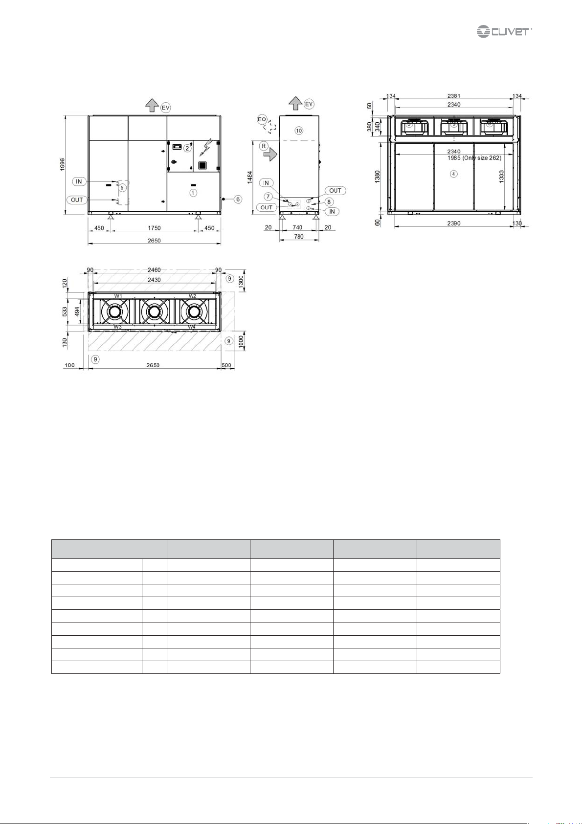
Sizes 262-302-352-402
DAB2S262_402_0 REV00
DATA 23/06/2016
(1) Compressor compartment
(2) General electrical panel
(3) Exhaust radial electric fans
(4) External exchanger
(5) Internal exchanger
(6) Electric line input
(7) Hydraulic ttings ush with unit (optional)
(8) Partial recovery water ttings (optional)
Size 262 302 352 402
A - Length mm 2650 2650 2650 2650
B - Width mm 780 780 780 780
C - Height mm 1996 1996 1996 1996
W1 Supporting Point kg 128 138 150 153
W2 Supporting Point kg 192 202 242 250
W3 Supporting Point kg 146 154 164 168
W4 Supporting Point kg 210 217 255 265
Shipping weight kg 667 704 804 829
Operating weight kg 676 711 810 836
La presenza di accessori opzionali può comportare una variazione signicativa dei pesi indicati in tabella.
(9) Functional clearances
(10) Separation line
(R) Outdoor air return
(EV) Vertical air exhaust (standard)
(EO) Horizontal air exhaust (optional)
M02S40N16-00 WSA-XEE 122-402 57
Page 58

Page intentionally left blank
58 WSA-XEE 122-402
M02S40N16-00
Page 59

Page intentionally left blank
M02S40N16-00 WSA-XEE 122-402 59
Page 60

CLIVET SPA
Via Camp Lonc 25, Z.I. Villapaiera - 32032 Feltre (BL) - Italy
Tel. + 39 0439 3131 - Fax + 39 0439 313300 - info@clivet.it
CLIVET UK LTD (Sales)
4 Kingdom Close, Segensworth East - Fareham, Hampshire - PO15 5TJ - United Kingdom
Tel. + 44 (0) 1489 572238 - Fax + 44 (0) 1489 573033 - info@clivet-uk.co.uk
CLIVET AIRCON LTD (Service and Maintenance Division)
Units F5&F6 Railway Triangle Ind Est, Walton Road - Portsmouth, Hampshire - PO6 1TG - United Kingdom
Tel. +44 (0) 2392 381235 - Fax. +44 (0) 2392 381243 - info@clivetaircon.co.uk
CLIVET ESPAÑA COMERCIAL S.L. (Sales)
Calle Gurb, 17 1º 1ª - 08500 Vic, Barcelona - España
Tel: +34 93 8606248 - Fax +34 93 8855392 - info@clivetcomercial.com
CLIVET ESPAÑA S.A.U. (Service and Maintenance Division)
Calle Real de Burgos Nº 12 - 28860 Paracuellos del Jarama, Madrid - España
Tel. +34 91 6658280 - Fax +34 91 6657806 - info@clivet.es
CLIVET GmbH
Hummelsbütteler Steindamm 84, 22851 Norderstedt - Germany
Tel. + 49 (0) 40 32 59 57-0 - Fax + 49 (0) 40 32 59 57-194 - info.de@clivet.com
CLIVET RUSSIA
Elektrozavodskaya st. 24, oce 509 - 107023, Moscow, Russia
Tel. + 74956462009 - Fax + 74956462009 - info.ru@clivet.com
CLIVET MIDEAST FZCO
Dubai Silicon Oasis (DSO), High Bay Complex, Ind Unit No. 3, PO BOX 28178, Dubai, UAE
Tel. + 9714 3208499 - Fax + 9714 3208216 - info@clivet.ae
CLIVET AIRCONDITIONING SYSTEMS PRIVATE LIMITED
4BA, Gundecha Onclave - Kherani Road,Saki Naka, Andheri (East) - Mumbai 400 072 - India
Tel. +91 22 6193 7000 - Fax +91 22 6193 7001 - info.in@clivet.com
www.clivet.com
 Loading...