

CLIVET ELFOROOM 3, ELFOROOM 11, ELFOROOM 17, ELFOROOM 5, ELFOROOM 15 Installation And Maintenance Manual
Page 1

ELFORoom2 3 - 5 - 11 - 15 - 17
Terminale ad acqua
I
GB
F
E
D
RU
MANUALE DI INSTALLAZIONE E MANUTENZIONE pagina 3
ISTALLATION AND MAINTENANCE MANUAL page 45
MANUEL D’INSTALLATION ET D’ENTRETIEN page 89
MANUAL DE INSTALACIÓN Y USO página 133
ANLEITUNG ZUR INSTALLATION UND WARTUNG Saite 177
ИНСТРУКЦИЯ ПО УСТАНОВКЕ И ЭКСПЛУАТАЦИИ
страница 221
M09160A13-02 13-02-14
Page 2

Gentile Cliente,
Ci congratuliamo con Lei per avere scelto un prodotto che fa parte della
famiglia ELFOSystem il sistema di climatizzazione a ciclo annuale che Le
offre la possibilità in un unico impianto di rispondere a tutte le necessità di
riscaldamento, condizionamento ed acqua calda sanitaria.
Clivet da anni opera per proporre al mercato sistemi in grado di assicurare il
massimo benessere per lungo tempo con elevata affidabilità, efficienza,
qualità e sicurezza.
L’obiettivo dell’azienda è quello di portare ai propri clienti sistemi evoluti, che
assicurino il comfort migliore, riducano i consumi di energia, i costi di
installazione e di manutenzione per l’intero ciclo di vita del sistema.
Con questo manuale, desideriamo fornire informazioni che potranno essere
utili in tutte le fasi: dalla ricezione, all’installazione, all’utilizzo e fino allo
smaltimento affinché un sistema così evoluto incontri le migliori modalità
d’istallazione ed utilizzo.
Cordiali saluti e buona lettura.
CLIVET Spa
I dati contenuti nel presente manuale non sono impegnativi e possono venire cambiati dal
costruttore senza obbligo di preavviso. Riproduzione anche parziale VIETATA
Page 3

INDICE
3
Generalità
1
Ricevimento
2
Posizionamento
3
Collegamenti idraulici
4
Collegamenti elettrici
5
Regolazione
6
Manutenzione
7
Dismissione
8
Informazioni tecniche
9
4
7
8
11
16
23
34
37
38
10
Rischi residui
42
Page 4
1 - GENERALITA'
4
1.1 MANUALE
Il manuale permette una corretta installazione, uso e
manutenzione dell’unità.
Fare particolare attenzione ad :
AVVERTENZE, indicano operazioni o informazioni
particolarmente importanti
DIVIETI, indicano operazioni che non si possono fare , che
compromettono la funzionalità della macchina o che possono
causare danni a cose o persone .
• Leggere con attenzione consente di risparmiare tempo
nelle varie operazioni.
• Seguire le indicazioni riportate per non incorrere in danni
a cose o persone.Le informazioni preliminari devono
essere lette prima di effettuare qualsiasi operazione
seguente.
1.2 AVVERTENZE GENERALI
Preliminari
L’ubicazione, l’impianto idraulico, frigorifero, elettrico e le
canalizzazioni dell’aria devono essere stabilite dal progettista
dell’impianto in accordo con la legislazione locale vigente .
Sull’unità può intervenire solo personale qualificato, come
previsto dalle normative in vigore.
Utilizzare l’unità in presenza di guasto o malfunzionamento:
• fa decadere la garanzia
• può compromettere la sicurezza della macchina
• può aumentare costi e tempi di riparazione .
Attenersi in qualsiasi operazione alle norme di sicurezza
locali.
Tenere fuori dalla portata di bambini il materiale di imballaggio
perché potenziale fonte di pericolo.
Riciclare e smaltire il materiale di imballaggio secondo le
norme locali.
Situazioni di rischio
L’unità è progettata e costruita in modo tale da non esporre a
rischio la salute e la sicurezza delle persone.
In fase di progetto non è possibile intervenire su tutte le cause
di rischio.
Leggere la sezione “Rischi residui” che riporta le situazioni
che possono dare origine a rischi per cose o persone.
Installazione, avviamento, manutenzione e riparazione
richiedono conoscenze specifiche; se effettuate da personale
inesperto possono portare danni a cose o persone.
Destinazione d’uso
Destinare l’unità solo al raffreddamento/riscaldamento di
acqua o acqua glicolata per il condizionamento attenendosi ai
limiti previsti dal bollettino tecnico e dal presente manuale.
Qualsiasi diverso utilizzo non comporta al costruttore impegno
o vincolo di alcun genere.
Installazione
Verificare che le caratteristiche della rete elettrica siano
conformi ai dati riportati sulla targhetta matricolare dell’unità.
Manutenzione
Prevedere ispezioni e manutenzioni periodiche per evitare e
limitare i costi di riparazione.
Togliere tensione prima di ogni operazione
.
Modifiche
Ogni tipo di modifica all’unità fa decadere la garanzia e la
responsabilità del costruttore.
Guasto o funzionamento difettoso
Disattivare subito l’unità in caso di guasto o
malfunzionamento.
Rivolgersi ad un centro assistenza autorizzato dal costruttore.
Richiedere l’utilizzo di ricambi originali.
Formazione utilizzatore
L’installatore deve istruire l’ utilizzatore; in particolare su :
• Accensione/spegnimento;
• Modifica setpoint;
• Messa a riposo
• Manutenzione;
• Cosa fare/non fare in caso di guasto.
Aggiornamento dati
I continui miglioramenti apportati al prodotto possono
determinare variazioni dei dati indicati in questo manuale.
Consultare il sito web www.clivet.it per ottenere dati
aggiornati.
1.3 INDICAZIONI PER L'UTENTE
Conservare questo manuale insieme allo schema elettrico in
luogo accessibile all’operatore.
Annotare i dati identificativi dell’unità in modo da poterli fornire
al centro assistenza in caso di richiesta di intervento (vedere il
paragrafo “Identificazione della macchina”).
Prevedere un libretto di macchina che consenta di tenere
traccia degli interventi effettuati sull’unità, in questo modo sarà
più facile cadenzare adeguatamente i vari interventi e sarà
facilitata una eventuale ricerca guasti.
In caso di guasto o malfunzionamento:
• disattivare subito l'unità
• rivolgersi ad un centro assistenza autorizzato.
• richiedere l'utilizzo di ricambi originali.
Chiedere all’installatore di essere formati su:
• accensione/spegnimento
• modifica setpoint
• messa a riposo
• manutenzione
• cosa fare/non fare in caso di guasto.
Page 5
1 - GENERALITA'
5
1.4 REGOLE FONDAMENTALI DI SICUREZZA
Ricordiamo che l’utilizzo di prodotti che impiegano energia
elettrica ed acqua, comporta l’osservanza di alcune regole
fondamentali di sicurezza quali:
• È vietato l’uso dell’apparecchio ai bambini e alle persone
inabili non assistite.
• È vietato toccare l’apparecchio se si è a piedi nudi e con
parti del corpo bagnate o umide.
• È vietata qualsiasi operazione di pulizia, prima di aver
scollegato l’apparecchio dalla rete di alimentazione
elettrica posizionando l’interruttore generale dell’impianto
su “spento”.
• È vietato modificare i dispositivi di sicurezza o di
regolazione senza l’autorizzazione e le indicazioni del
costruttore dell’apparecchio.
• È vietato tirare, staccare, torcere i cavi elettrici
fuoriuscenti dall’apparecchio, anche se questo è
scollegato dalla rete di alimentazione elettrica.
• È vietato introdurre oggetti e sostanze attraverso le griglie
di aspirazione e mandata d’aria.
• È vietato aprire gli sportelli di accesso alle parti interne
dell’apparecchio, senza aver prima posizionato
l’interruttore generale dell’impianto su “spento”.
• È vietato disperdere e lasciare alla portata di bambini il
materiale dell'imballo in quanto può essere potenziale
fonte di pericolo.
• È vietato salire con i piedi sull’apparecchio e/o
appoggiarvi qualsiasi tipo di oggetto.
• L’apparecchio può raggiungere temperature, sui
componenti esterni, superiori ai 70°C.
PRESTARE MOLTA ATTENZIONE AL CONTATTO,
PERICOLO SCOTTATURE.
• dati elettrici
• logo e indirizzo del costruttore
Numero di matricola
Identifica in modo univoco ciascuna macchina.
Permette di individuare i ricambi specifici per la macchina
Richieste di intervento
Annotare dall’etichetta matricolare i dati caratteristici e ripor-
tarli in tabella in modo da averli facilmente disponibili in caso
di necessità.
In caso di richiesta di intervento fornire sempre i dati.
Serie
Grandezza
Numero di matricola
Anno di produzione
Schema elettrico
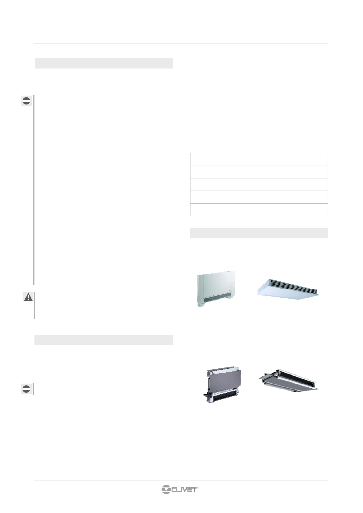
1.6 VERSIONI DELLA MACCHINA
Verticale / orizzontale a vista
1.5 IDENTIFICAZIONE DELLA MACCHINA
Etichetta matricolare
L’ etichetta matricolare è posizionata sull’unità, generalmente
in prossimità del quadro elettrico, e consente di risalire a tutte
le caratteristiche della macchina.
L'etichetta matricolare non deve mai essere rimossa.
L’etichetta matricolare riporta le indicazioni previste dalle nor-
mative, in particolare :
Verticale / orizzontale ad incasso
• il tipo di macchina
serie → ELFOROOM
grandezza → 3 ( o 5 o 11 o 15 o 17)
2
• il numero di matricola, esempio : Axxxxxxxxxxx
• l’anno di fabbricazione
• il numero di schema elettrico
Page 6

1 - GENERALITA'
6
1.7 ACCESSORI FORNITI SEPARATAMENTE
Ogni accessorio è fornito con le istruzioni di montaggio.
• KASPX
Kit aspirazione
• GMX
Griglia di mandata
• GRA1X
Griglia di aspirazione aria
• PR90MX
Plenum a 90° di mandata aria
• PMSTX
Kit plenum di mandata superiore telescopico
• KV3B4X
Kit valvola 3 vie con testina elettrotermica e bilanciamento per impianto 4 tubi
(disponibile solo con opzioni: B4T)
• KV3VBX
Kit valvola 3 vie con testina elettrotermica e bilanciamento
• HIDE1X
Selettore 3 velocità + on/off per installazione a muro (disponibile solo con opzioni: 3V010)
• HIDE2X
Controllo ambiente semplificato E/I +3V +on/off per installazione a muro (disponibile solo con opzioni: 3V010)
• HIDE3X
Controllo ambiente plurifunzionale per installazione a muro (disponibile solo con opzioni: 3V010)
• HID-T2X
Controllo ambiente elettronico HID-T2
(esterno solo temperatura)
• HID-T3X
Controllo ambiente elettronico HID-T3
(esterno temperatura e umidità)
• HID-TI2X
Controllo ambiente elettronico da incasso HID-TI2
(da incasso solo temperatura)
• KCMDX
Cavi per collegamento motore per unità con attacchi a destra
• PCIX
Pannello di chiusura ad incasso
•
BACKVX
Pannello posteriore verniciato per unità a vista
• CSFIX
Cassaforma per installazione a incasso
• FXPPX
Kit staffe di fissaggio a pavimento
• KPDX
Kit Piedini
Page 7
2 - RICEVIMENTO
7
2.1 INFORMAZIONI PRELIMINARI
Generali
Operare rispettando le normative di sicurezza in vigore.
Per le informazioni di dettaglio (dimensioni, pesi,
caratteristiche tecniche, etc) far riferimento al capitolo
INFORMAZIONI TECNICHE.
Per effettuare le operazioni usare dispositivi di
protezione: guanti , occhiali ecc.
Stoccaggio
Rispettare le indicazioni riportate sull’esterno
dell’imballo.
Movimentazione
Verificare peso dell’unità e capacità del mezzo di
sollevamento.
Individuare i punti critici nel percorso di
movimentazione
(percorsi sconnessi, rampe, scalini, porte).
Considerare che il baricentro potrebbe essere spostato
rispetto al centro dell'unità .
Prima di iniziare la movimentazione assicurarsi che
l’unità sia in equilibrio stabile.
Rimozione imballo
Fare attenzione a non danneggiare l’unità.
Riciclare e smaltire il materiale di imballaggio secondo
le norme locali.
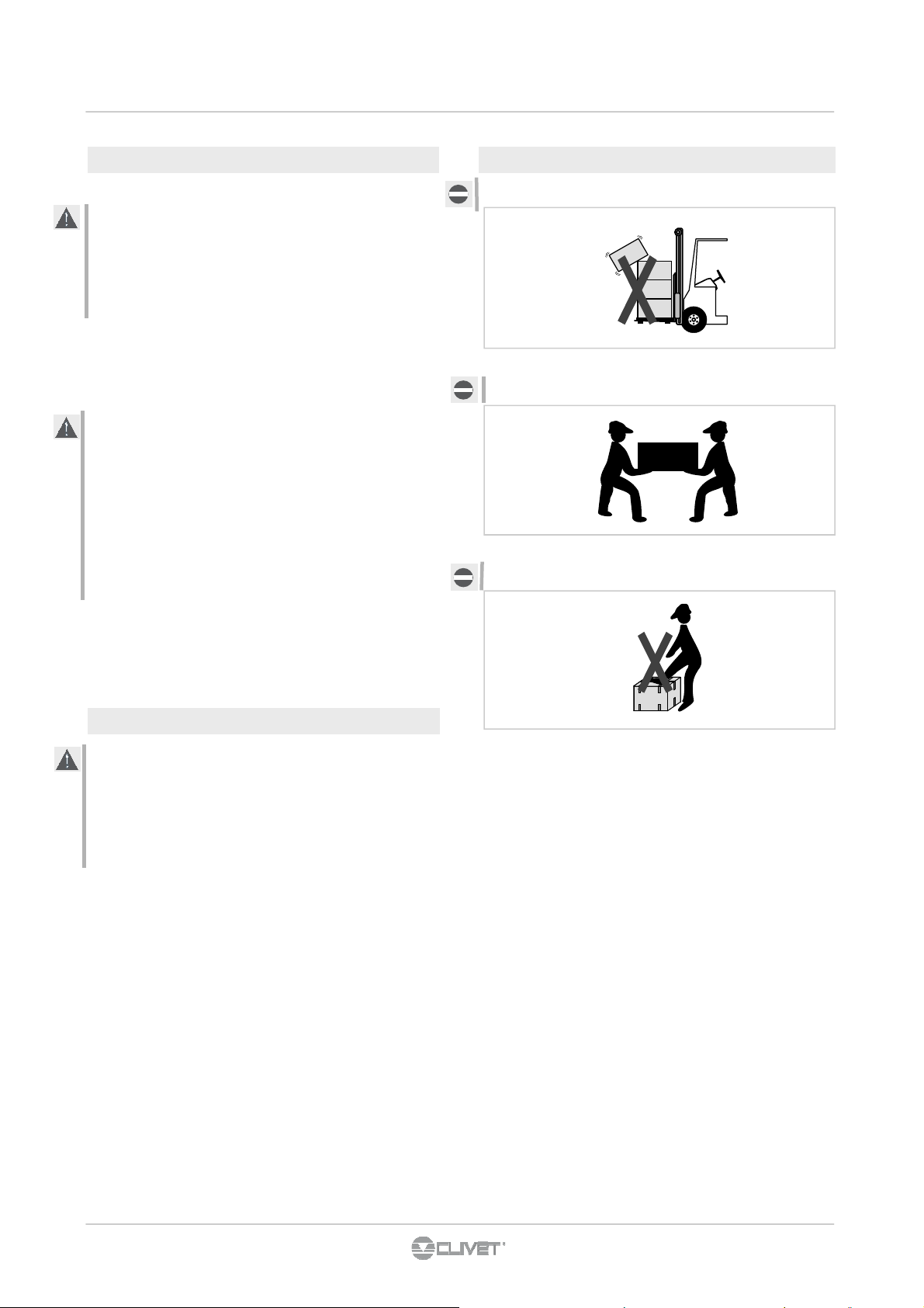
2.3 MOVIMENTAZIONE
non lasciare gli imballi sciolti durante il trasporto
non spostare l'unità da soli
non calpestare
2.2 CONTROLLO ALL’ARRIVO
Prima di accettare la consegna controllare:
• Che l’unità non abbia subito danni nel trasporto
• Che il materiale consegnato corrisponda a quanto
indicato sul documento di trasporto confrontando i
dati con l’etichetta matricolare posizionata
sull’imballo.
In caso di danni o anomalie :
• annotare immediatamente sul documento di tra-
sporto il danno riscontrato e riportare la dicitura:
“Ritiro con riserva per evidenti ammanchi/danni da
trasporto”.
• contestare via fax e con raccomandata A.R. al vet-
tore e al fornitore.
Le contestazioni devono essere effettuate entro 8 giorni dal ricevimento, le segnalazioni oltre tale termine
non sono valide.
Page 8
3 - POSIZIONAMENTO
8
3.1 INFORMAZIONI PRELIMINARI
Generali
Operare rispettando le normative di sicurezza in vigore.
Per le informazioni di dettaglio (dimensioni, pesi,
caratteristiche tecniche, etc) far riferimento al capitolo
INFORMAZIONI TECNICHE .
Per effettuare le operazioni usare dispositivi di protezione:
guanti, occhiali ecc.
Nel posizionamento considerare questi elementi :
• spazi tecnici richiesti dalla macchina e dall’impianto
• scelta del luogo di installazione della macchina
• collegamenti elettrici
• collegamenti idraulici
• aria / canalizzazioni aerauliche
Trascurare questi aspetti può diminuire prestazioni e vita
operativa dell’unità.
3.2 SPAZI FUNZIONALI
Gli spazi funzionali hanno lo scopo di:
• garantire il buon funzionamento dell’unità
• consentire le operazioni di manutenzione
• salvaguardare gli operatori autorizzati e le persone
esposte.
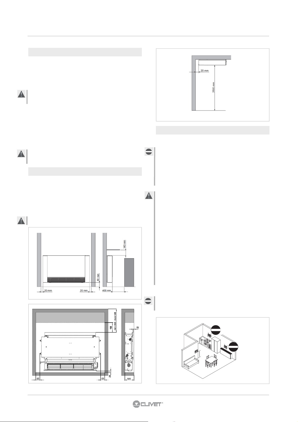
Rispettare gli spazi funzionali indicati in figura .
3.3 POSIZIONAMENTO
Evitare l’installazione dell’unità in prossimità di :
• posizioni soggette all’esposizione diretta dei raggi solari;
• in prossimità di fonti di calore
• in ambienti umidi e zone con probabile contatto con
l’acqua
• in ambienti con vapori d’olio
• in ambienti sottoposti ad alte frequenze.
Accertarsi che :
• la parete su cui si intende installare l’unità abbia una
struttura e una portata adeguata
• la zona della parete interessata non sia percorsa da
tubazioni o linee elettriche
• la parete interessata sia perfettamente in piano
• sia presente un’area libera da ostacoli che potrebbero
compromettere la circolazione dell’aria in ingresso ed
uscita
• la parete di installazione sia possibilmente una parete di
perimetro esterno per consentire lo scarico della
condensa all’esterno
• in caso di installazione a soffitto il flusso dell’aria non sia
rivolto direttamente verso le persone.
Se previsto un termostato ambiente a parete - OPZIONE - :
installare il termostato ambiente lontano da fonti di calore
(caloriferi, raggi del sole, cucine), da porte , finestre ecc.
OK
1,5 m
Page 9

3 - POSIZIONAMENTO
9
3.4 INSTALLAZIONE
Le seguenti descrizioni sulle varie fasi di montaggio ed i relativi disegni fanno riferimento ad una versione di macchina con attacchi a
sinistra. Le descrizioni per le operazioni di montaggio delle macchine con attacchi a destra sono le medesime.
Solo le immagini sono da considerarsi rappresentate specularmente.
3.5 APERTURA FIANCHI
• sollevare A
• svitare B
• spostare a sinistra C
• alzare C
3.6 INSTALLAZIONE A SOFFITTO O ORIZZONTALE
• sollevare A
• svitare B
• spostare a destra D
• alzare D
• Utilizzare la dima di carta, e tracciare a soffitto la posizione delle due staffe di fissaggio e delle due viti posteriori.
• Forare con una punta adeguata ed infilare i tasselli (2 per ogni staffa) (fig. 3.1 rif. A) ; fissare le due staffe (fig. 3.1 rif. B). Non
stringere eccessivamente le viti.
• Infilare la macchina sulle due staffe, mantenendola in posizione quindi fissare le due viti nei tasselli posteriori (fig. 3.1 rif. C), una
per ogni lato.
• Si raccomanda di conferire un’adeguata inclinazione dell’unità verso il tubo di drenaggio per agevolare la fuoriuscita dell’acqua
(fig. 3.1 rif. D).
• Stringere definitivamente tutte le 6 viti di fissaggio.
fig 3.1
Page 10

3 - POSIZIONAMENTO
10
3.7 INSTALLAZIONE A PARETE O PAVIMENTO VERTICALE
In caso di montaggio a pavimento con piedini, rispettare l’altezza minima da terra di 80mm. e fare riferimento ai singoli fogli
d’istruzione in dotazione e al relativo manuale .
• Utilizzare la dima di carta, e tracciare sulla parete la posizione delle due staffe di fissaggio (fig. 3.2).
• Forare con una punta adeguata ed infilare i tasselli (2 per ogni staffa)(fig. 3.3 rif. A); fissare le due staffe (fig. 3.3 rif. B). Non
stringere eccessivamente le viti, in modo da poter effettuare una regolazione delle staffe con una bolla di livello (fig. 3.4).
• Bloccare definitivamente le due staffe serrando completamente le quattro viti.
• Verificarne la stabilità spostando manualmente le staffe verso destra e sinistra, alto e basso.
• Montare l’unità, verificando il corretto aggancio sulle staffe e la sua stabilità (fig. 3.5).
fig 3.2 fig 3.3
fig 3.4
fig 3.5
Page 11

4 - COLLEGAMENTI IDRAULICI
11
4.1 DIAMETRO TUBAZIONI
Ingresso acqua : EUROKONUS 3/4
Uscita acqua : EUROKONUS 3/4
Scarico condensa : Ø 14 mm (diametro interno)
Per la posizione delle tubazioni per gli attacchi a parete fare
riferimento ai disegni riportati nei paragrafi successivi, in base
alla specifica configurazione.
4.2 COLLEGAMENTI
La scelta ed il dimensionamento delle linee idrauliche è demandato per competenza al progettista, che dovrà operare
secondo le regole della buona tecnica e delle legislazioni
vigenti.
Isolare le linee idrauliche / In figura componenti opzionali
Per effettuare i collegamenti :
• posizionare le linee idrauliche
• serrare le connessioni utilizzando il metodo “chiave contro
chiave” ( rif. B)
• verificare l’eventuale perdita di liquido
• rivestire le connessioni con materiale isolante ( rif. C).
Le linee idrauliche e le giunzioni devono essere isolate termicamente.
Evitare isolamenti parziali delle tubazioni.
Evitare di stringere troppo per non danneggiare l’isolamento.
Per la tenuta idrica delle connessioni filettate utilizzare canapa
e pasta verde; l’utilizzo di nastro di teflon è consigliato in presenza di liquido antigelo nel circuito idraulico.
4.3 SCARICO CONDENSA
La rete di scarico della condensa deve essere
opportunamente dimensionata (diametro interno tubo minimo
16 mm) e la tubazione posizionata in modo da mantenere
sempre lungo il percorso una determinata pendenza, mai
inferiore a 1%.
• Nell’installazione verticale il tubo di scarico si collega
direttamente alla vaschetta di scarico, posizionata in
basso sulla spalla laterale, sotto gli attacchi idraulici.
• Nell’installazione orizzontale il tubo di scarico viene
allacciato a quello già presente sulla macchina.
Se possibile fare defluire il liquido di condensa direttamente in
una grondaia o in uno scarico di “acqua bianche”.
In caso di scarico nella rete fognaria, si consiglia di realizzare
un sifone per impedire la risalita dei cattivi odori verso gli
ambienti. La curva del sifone deve essere più in basso
rispetto alla bacinella di raccolta condensa.
Nel caso si debba scaricare la condensa all’interno di un
recipiente, questo deve restare aperto all’atmosfera ed il tubo
non deve essere immerso in acqua, evitando fenomeni di
adesività e contropressioni che ostacolerebbero il libero
deflusso.
Nel caso si debba superare un dislivello che ostacolerebbe il
deflusso della condensa, è necessario montare una pompa
(kit accessorio):
• per l’installazione verticale montare la pompa sotto la
vaschetta di drenaggio laterale;
• per l’installazione orizzontale la posizione della pompa
deve essere decisa in funzione delle specifiche esigenze.
In ogni caso consultare le specifiche istruzioni presenti nel kit
pompa smaltimento condensa.
Al termine dell’installazione,verificare il corretto deflusso del
liquido di condensa versando molto lentamente (circa 1/2 l di
acqua in circa 5-10 minuti) nella vaschetta di raccolta.
Page 12
4 - COLLEGAMENTI IDRAULICI
12
4.3.2 Scarico condensa versione VERTICALE 4.3.1 Scarico condensa versione ORIZZONTALE
Per il montaggio della bacinella orizzontale fare riferimento
alle istruzioni contenute nei kit .
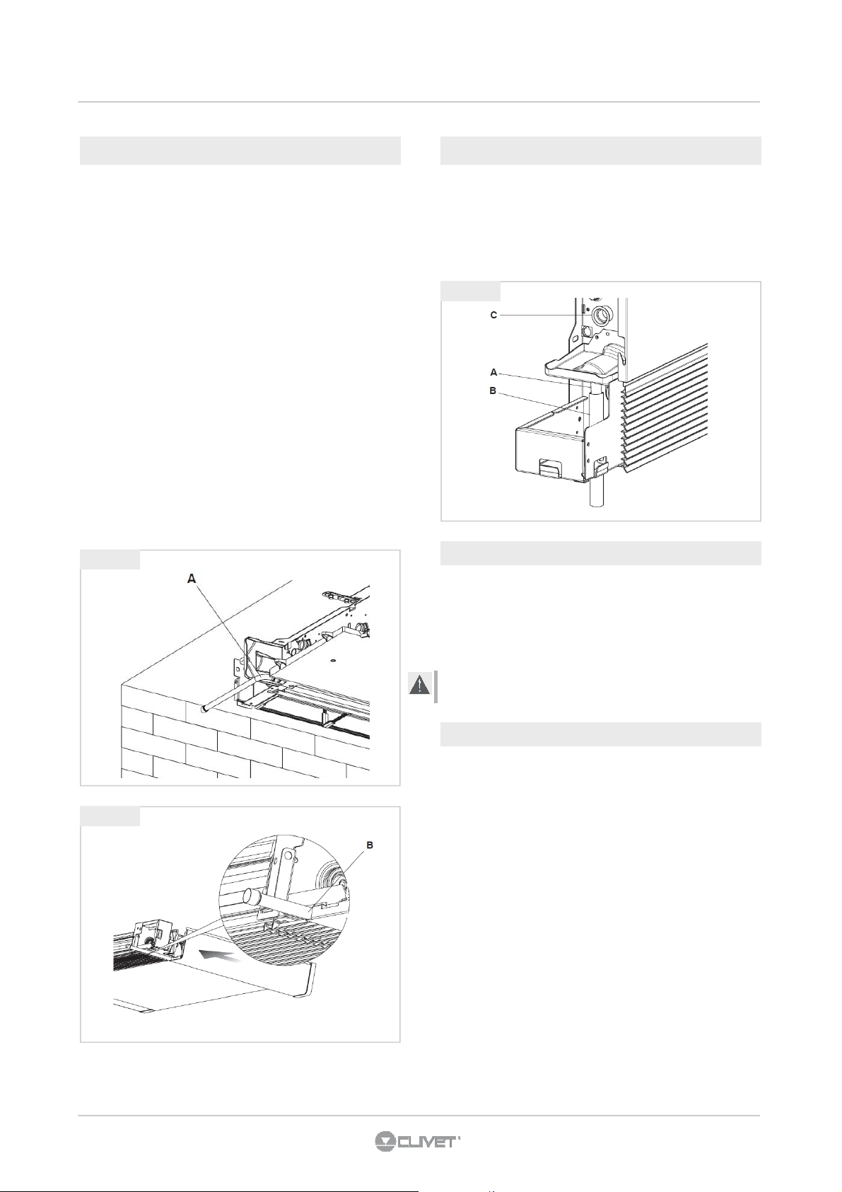
• verificare che il tubo ad “L” e quello in gomma flessibile
siano correttamente allacciati alla bacinella (fig. 4.1 rif. A).
• infilare il fianco della macchina tenendo il tubo in posizio-
ne a battuta sulla griglia anteriore.
• chiudere definitivamente il fianco verificando che il tubo
rimanga bloccato nell’apposito scasso presente sul fianco
(fig. 4.2 rif. B).
Per l’installazione orizzontale osservare le seguenti avvertenze :
• assicurarsi che la macchina sia installata perfettamente a
livello, o con una leggera inclinazione nel verso dello scarico della condensa;
• coibentare bene i tubi di mandata e ritorno fino all’imbocco
della macchina, in modo da impedire gocciolamenti di
condensa all’esterno della bacinella di raccolta stessa ;
• coibentare il tubo di scarico della condensa della bacinella
per tutta la sua lunghezza.
fig 4.1
• Collegare al raccordo di scarico della vaschetta raccogli
condensa (fig. 4.3 rif. A) un tubo per il deflusso del liquido
(fig. 4.3 rif. B) bloccandolo in modo adeguato.
• Verificare che la prolunga rompigoccia (fig. 4.3 rif. C) sia
presente e correttamente installata.
fig 4.3
4.4 ROTAZIONE ATTACCHI
Le operazioni descritte, e le immagini relative, si riferiscono ad
una macchina con attacchi a sinistra su cui necessita la rotazione degli attacchi sul lato destro.
Nel caso si abbia a disposizione una macchina con attacchi a
destra con necessità di rotazione a sinistra, la sequenza delle
operazioni è la medesima, solo le immagini sono da considerarsi speculari.
Per la connessione del motore ai kit di comando è necessario
utilizzare l’apposito cablaggio opzionale .
fig 4.2
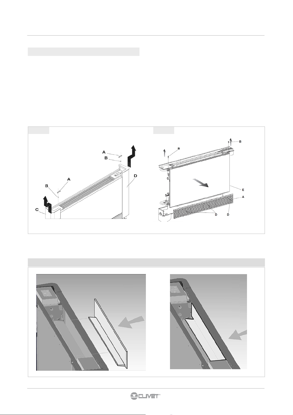
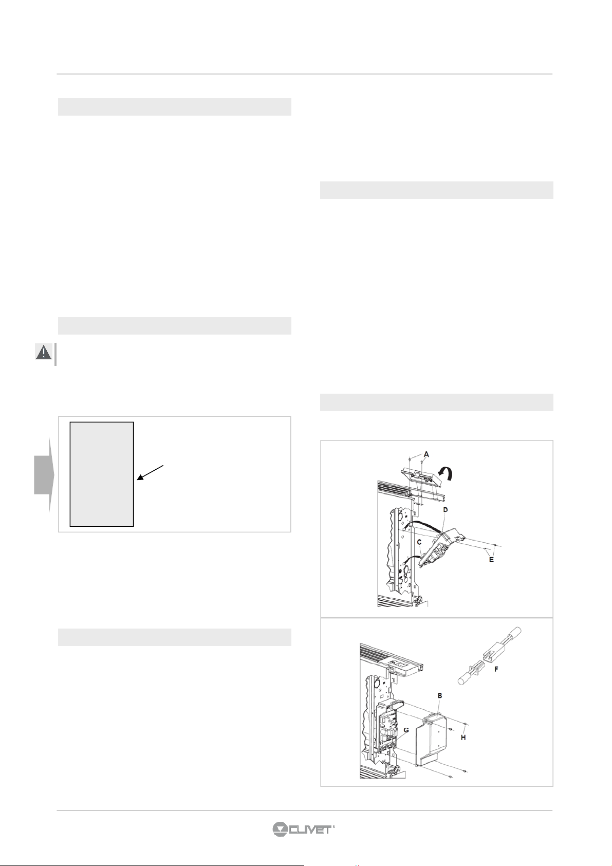
4.4.1 Smontaggio pannellature
• Smontare la griglia superiore (fig. 4.4) svitando le due viti
di fissaggio .
• Sul lato sinistro svitare la vite che fissa il fianchetto sini-
stro, spostarlo leggermente verso sinistra e sollevarlo.
• Sul alto opposto sollevare il coperchietto di copertura vite
e svitarla
• Spostare leggermente verso destra il fianchetto e sollevar-
lo.
• Togliere la griglia anteriore inferiore (fig. 4.5 rif. A).
• Svitare le viti (fig. 4.5 rif. B-D) di fissaggio pannello fronta-
le (fig. 4.5 rif. E) e smontarlo.
Page 13
4 - COLLEGAMENTI IDRAULICI
13
4.4.2 Smontaggio pannello di comando
• Posizionare l’interruttore generale dell’impianto su spento.
• Utilizzare, per la connessione del motore, l’apposito
• Smontare lo sportellino di accesso gruppi collettori (fig.
4.6 rif. A) svitando le due viti di fissaggio (fig. 4.6 rif. B).
• Smontare il pannello di comando (fig. 4.6 rif. C) svitando
le due viti di fissaggio (fig. 4.6 rif. D).
• Staccare la scheda di controllo (fig. 4.6 rif. E).
• Invertire le posizioni di montaggio dello sportellino (fig. 4.6
• Smontare la vaschetta di raccolta condensa (fig. 4.6 rif. F) e
• Staccare i connettori dei collegamenti elettrici.
• Sfilare i cablaggi all’interno della macchina e reinfilarli dal
lato opposto.
fig 4.4 fig 4.5
cablaggio per attacchi a destra disponibile come
accessorio.
rif. A) con il pannello di comando (fig. 4.6 rif. C) e rimontarli
nelle rispettive posizioni.
rimontarla sul lato opposto con le relative viti di fissaggio
(fig. 4.6 rif. G).
Il pannello isolante deve essere nella posizione indicata, altrimenti la batteria non viene attraversata dal'aria
Page 14
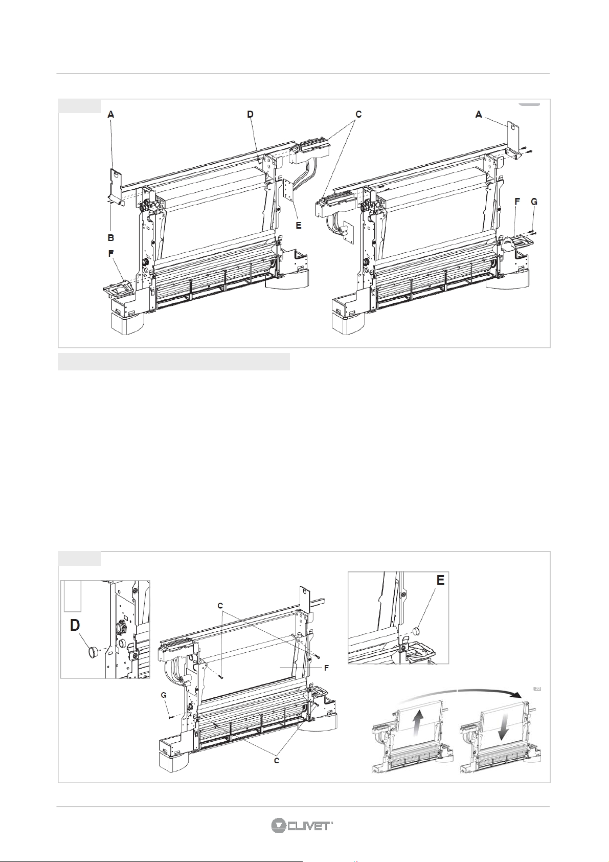
fig 4.6
14
4 - COLLEGAMENTI IDRAULICI
4.4.3 Rotazione batteria per attacchi a DX
• svitare le quattro viti che fissano lo scambiatore (fig. 4.7
rif. C);
• sfilare la sonda acqua della batteria;
• sfilare lo scambiatore (fig. 4.7 rif. F);
• sfilare la prolunga rompigoccia dalla vaschetta centrale
(fig. 4.7 rif. D);
• sul lato opposto sfilare il tappo sul foro di evacuazione
condensa (fig. 4.7 rif. E);
• svitare la vite di fissaggio vaschetta di raccolta condensa
centrale (fig. 4.7 rif. G), portare la vaschetta in appoggio
fig 4.7
sul lato opposto in modo che dalla struttura fuoriesca il
bocchettone di attacco per la prolunga rompigoccia indi
bloccare la bacinella con la vite precedentemente smontata;
• reinfilare la prolunga rompigoccia e sul lato opposto il tappo;
• ruotare lo scambiatore portando gli attacchi sul lato opposto,
e reinfilarlo sulla macchina
• avvitare tutte le viti di fissaggio dello scambiatore
• Completate tutte le operazioni descritte rimontate tutti i
componenti precedentemente smontati seguendo le
operazioni di smontaggio in senso inverso.
Page 15
4 - COLLEGAMENTI IDRAULICI
15
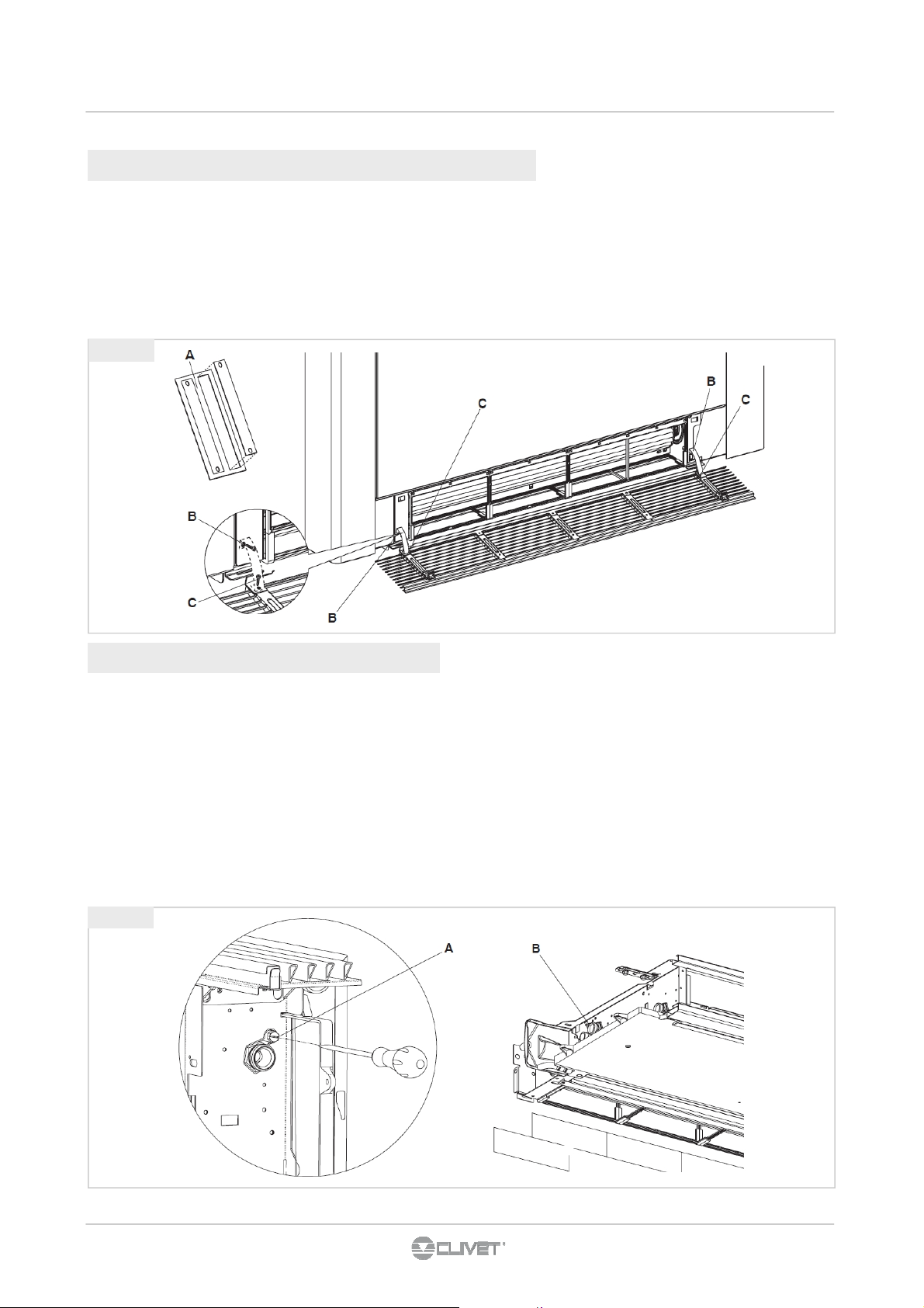
4.5 MONTAGGIO SOSTEGNO SICUREZZA GRIGLIA ANTERIORE
Nel caso in cui il ventilconvettore venga installato in posizione
orizzontale, per garantire la sicurezza delle operazioni di
pulizia/sostituzione filtri, devono obbligatoriamente essere
montate, dall'installatore, le due fascette di sicurezza presenti
nel sacchetto in dotazione assieme al manuale di istruzioni ed
agli accessori.
• Separare le due fascette (fig. 4.8 rif. A);
fig 4.8
• aprire la griglia anteriore e svitare completamente le viti di
fissaggio delle molle (fig. 4.8 rif. B);
• fissare le due fascette riavvitando le viti (fig. 4.8 rif. B);
• fissare l'altra parte delle fascette alla griglia per mezzo delle
viti in dotazione (fig. 4.8 rif. C);
• chiudere la griglia.
4.6 RIEMPIMENTO IMPIANTO
Durante l’avviamento dell’impianto assicurarsi che il detentore
sul gruppo idraulico sia aperto.
Se ci si trova in mancanza di alimentazione elettrica e la termovalvola è già stata alimentata precedentemente sarà necessario utilizzare l’apposito cappuccio per premere
l’otturatore della valvola per aprirla.
• Aprire tutti i dispositivi di intercettazione dell’impianto
(manuali o automatici);
• Iniziare il riempimento aprendo lentamente il rubinetto di
carico acqua impianto;
fig 4.9
• Per i modelli installati in posizione verticale agire
(utilizzando un cacciavite) sullo sfiato della batteria posto
più in alto (fig.4.9 rif.A);
• per gli apparecchi installati in posizione orizzontale agire
sullo sfiato posizionato più in alto (fig.4.9 rif.B);
• Quando comincia ad uscire acqua dalle valvole di sfiato
dell’apparecchio, chiuderle e continuare il caricamento fino
al valore nominale previsto per l’impianto.
• Verificare la tenuta idraulica delle guarnizioni.
• Si consiglia di ripetere questa operazione dopo che
l’apparecchio ha funzionato per alcune ore e di controllare
periodicamente la pressione dell’impianto.
Page 16
5 - COLLEGAMENTI ELETTRICI
16
5.1 INFORMAZIONI PRELIMINARI
Le caratteristiche delle linee devono essere determinate da
personale abilitato alla progettazione di impianti elettrici,
attenendosi alle normative in vigore.
I dispositivi di protezione della linea di alimentazione dell’unità
devono essere in grado di interrompere la corrente di corto
circuito presunta, il cui valore deve essere determinato in
funzione delle caratteristiche dell’impianto.
La sezione dei cavi di alimentazione e del cavo di protezione
deve essere determinata in funzione delle caratteristiche delle
protezioni adottate.
Tutte le operazioni di carattere elettrico devono essere
eseguite da personale in possesso dei requisiti previsti dalle
normative in vigore, istruito sui rischi correlati a tali operazioni.
Operare rispettando le normative di sicurezza in vigore
5.2 DATI ELETTRICI
L’ etichetta matricolare riporta i dati elettrici specifici dell’unità,
compresi eventuali accessori elettrici.
I dati elettrici indicati nel bollettino tecnico e nel manuale sono
riferiti all’unità standard, accessori esclusi. Fare quindi
riferimento ai dati riportati in etichetta matricolare .
5. Proteggere i cavi utilizzando passacavi di misura
adeguata
6. Prima di alimentare elettricamente l’unità, assicurarsi che
siano state ripristinate tutte le protezioni che erano state
rimosse durante i lavori di allacciamento elettrico.
5.4 LINEE SEGNALI / DATI
Non superare la massima distanza consentita, che varia in
funzione del tipo di cavo e del segnale .
Posare i cavi lontano da linee di potenza, con tensione
diversa, o che emettano disturbi di origine elettromagnetica.
Evitare di posare i cavi nelle vicinanze di apparecchiature che
possono creare interferenze elettromagnetiche.
Evitare la posa in parallelo con altri cavi, eventuali incroci con
altri cavi sono ammessi solo se a 90°.
Lo schermo va connesso ad una terra priva di disturbi.
Garantire la continuità dello schermo per tutta l’estensione del
cavo .
Rispettare le indicazioni relative a impedenza, capacità,
attenuazione.
5.5 ACCESSO QUADRO ELETTRICO
etichetta
matricolare
F.L.A. full load ampere
corrente assorbita alle massime condizioni ammesse
F.L.I. Full load input
Potenza assorbita a pieno carico
( alle massime condizioni ammesse )
n° SCHEMA ELETTRICO
TENSIONE ALIMENTAZIONE
FLA (A)
FLI (kW)
5.3 COLLEGAMENTI
1. Fare riferimento allo schema elettrico dell’unità (il numero
di schema elettrico è indicato nell’etichetta matricolare)
2. Verificare che la rete abbia caratteristiche conformi ai dati
riportati sulla targhetta matricolare
3. Prima di iniziare i lavori verificare che il dispositivo di
sezionamento alla partenza della linea di alimentazione
dell’unità sia aperto, bloccato e dotato dell’apposito
cartello di segnalazione
4. Realizzare per primo il collegamento di messa a terra
Aprire i fianchi : istruzioni al paragrafo 3.5.
Page 17
5 - COLLEGAMENTI ELETTRICI
17
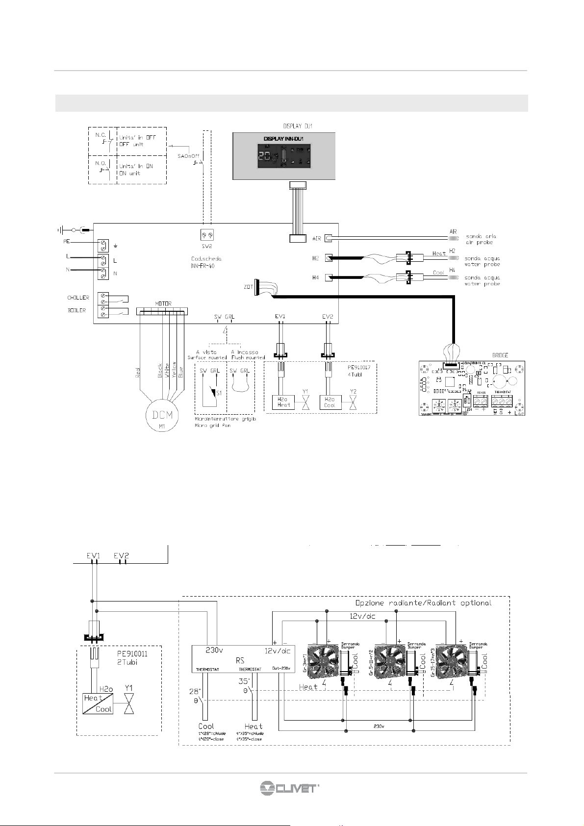
5.6 Collegamento con termostato a bordo
4 tubi : Y1 + Y2
2 tubi : Y1
BOILER uscita consenso riscaldamento (boiler-caldaia)
contatto pulito max 1A
CHILLER uscita consenso raffreddamento (chiller)
contatto pulito max 1A
SW2 ON / OFF remoto
H2 sonda temperatura acqua (4T → riscaldamento)
2T → raffreddamento / riscaldamento
H4 sonda temperatura acqua (4T → raffreddamento)
S1 microinterruttore sicurezza griglia
Y1 Elettrovalvola acqua (4T → riscaldamento)
(2T → riscaldamento / raffreddamento)
Y2 Elettrovalvola acqua (4T → raffreddamento)
Page 18
5 - COLLEGAMENTI ELETTRICI
18
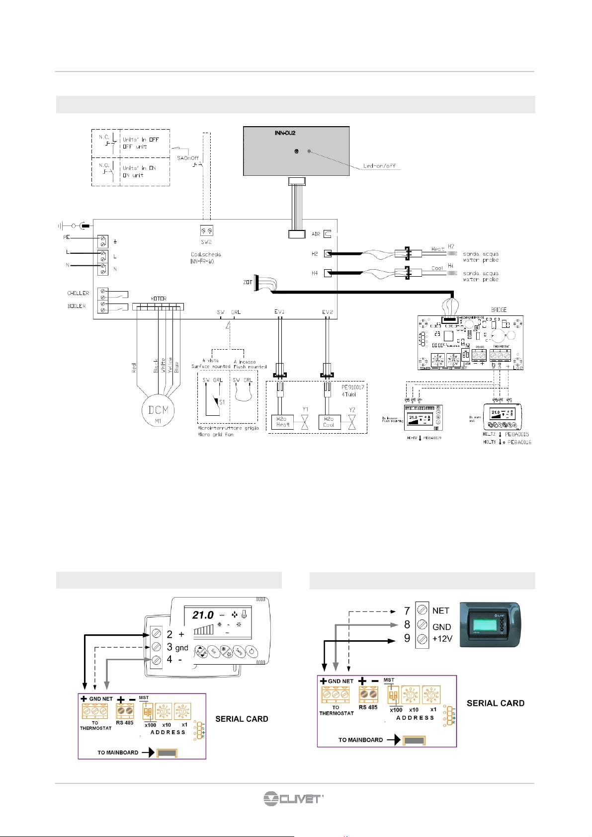
5.7 Collegamento a termostato ambiente elettronico HID-Txx
4 tubi : Y1 + Y2
2 tubi : Y1
BOILER uscita consenso riscaldamento (boiler-caldaia)
contatto pulito max 1A
CHILLER uscita consenso raffreddamento (chiller)
contatto pulito max 1A
SW2 ON / OFF remoto
H2 sonda temperatura acqua (4T → riscaldamento)
2T → raffreddamento / riscaldamento
TERMOSTATO HID-T2 / T3
H4 sonda temperatura acqua (4T → raffreddamento)
S1 microinterruttore sicurezza griglia
off = ventilazione spenta a setpoint soddisfatto
Y1 Elettrovalvola acqua (4T → riscaldamento)
(2T → riscaldamento / raffreddamento)
Y2 Elettrovalvola acqua (4T → raffreddamento)
Opzione radianti: vedere 5.6
TERMOSTATO HID-Ti2
Page 19

5 - COLLEGAMENTI ELETTRICI
19
5.8 MINIRETE - MAX 9 ELFORoom2
* Resistenza terminazione rete 120 Ω - a cura cliente
5.9 ELFOSystem GAIA Edition
1. Bus RS485
2. ELFOControl Home
3. GAIA
4. ELFOFRESH
5. zona con 2 ELFOROOM
comanda entrambi i terminali
6. zona con 1 ELFOROOM
comanda il terminale
7. ELFOROOM
entrambi i terminali
8. ELFOROOM
2
2
con tastiera e termostato HID-T3 che comanda
2
con termostato a bordo
2
con tastiera e termostato HID-Ti2 che
2
con tastiera e termostato HID-Ti2 che
Page 20

5 - COLLEGAMENTI ELETTRICI
20
5.10 Collegamento con controllo elettronico 4 velocità
AIR sonda temperatura aria
H2 sonda temperatura acqua
S1 microinterruttore sicurezza griglia
Y1 Elettrovalvola acqua
Page 21
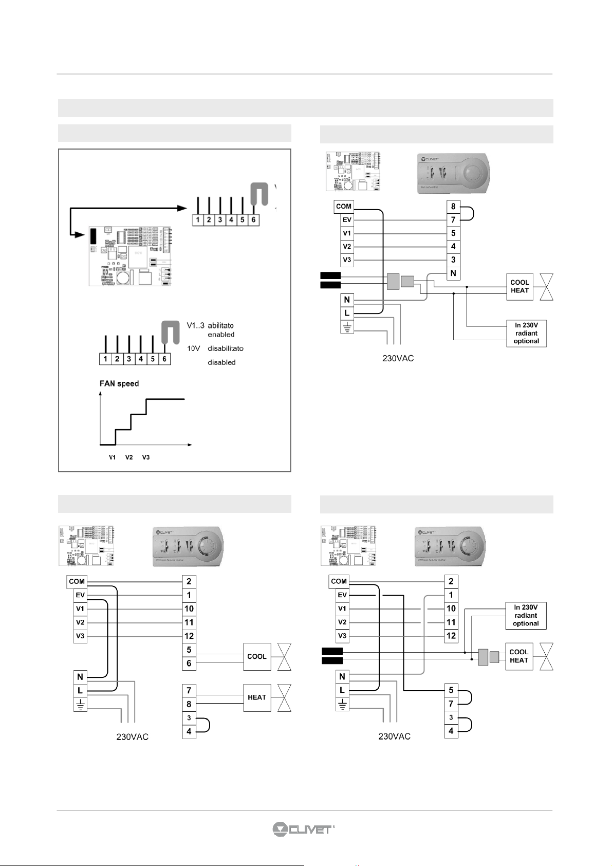
5.11 Collegamenti termostati
21
5 - COLLEGAMENTI ELETTRICI
Abilitare comando 3 velocità
Termostato HID-E1 - impianto 2 tubi
Termostato HID-E2 - impianto 4 tubi
Termostato HID-E2 - impianto 2 tubi
Page 22

5 - COLLEGAMENTI ELETTRICI
22
Termostato HID-E3 - impianto 4 tubi
H2O sonda temperatura acqua
Termostato HID-E3 - impianto 2 tubi
H2O sonda temperatura acqua
Abilitare comando 0-10V
10v = fan 1400 rpm
1v = fan 450 rpm
<1v = fan off
Page 23

6.1 TERMOSTATO A BORDO MACCHINA
23
6 - REGOLAZIONE
display tasti
display
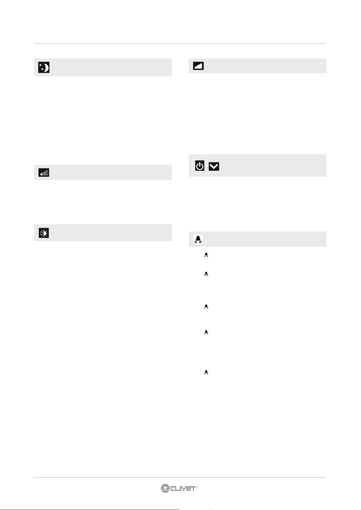
funzionamento automatico
funzionamento silenzioso
massima velocità ventilatore
funzionamento notturno
riscaldamento
raffreddamento
supervisione da webserver
allarme attivo
ON / Standby
Tenere premuto il tasto ON stand-by per circa 2 secondi .
La mancanza di qualsiasi segnalazione luminosa dal display
identifica lo stato di "stand-by" (assenza di funzione).
Quando il comando si trova in questo modo di funzionamento
garantisce una sicurezza antigelo.Nel caso in cui la
temperatura ambiente scenda al di sotto dei 5°C vengono
attivate le uscite elettrovalvola acqua calda e consenso
caldaia.
regolazione automatica velocità ventilatore
Tener premuto il tasto AUTO. L’attivazione della funzione
viene segnalata dall'accensione del relativo simbolo a display
La regolazione della velocità di ventilazione avverrà
automaticamente tra un valore minimo ed un valore massimo,
secondo la effettiva distanza della temperatura ambiente dal
setpoint impostato in base ad un algoritmo di tipo PI.
tasti
ON / Standby
aumenta temperatura impostata
diminuisce temperatura
regolazione automatica velocità ventilatore
funzionamento notturno
minima velocità ventilazione
riscaldamento / raffreddamento
massima velocità di ventilazione
modificare temperatura impostata
Impostare con l'ausilio dei due tasti aumento e diminuzione il
valore di temperatura desiderato in ambiente visualizzato sui
3 digit del display.
Il range di regolazione va da 16 a 28 °C, con risoluzione di
0,5°C, ma sono consentiti anche i valori fuori scala di 5°C e di
40°C.
Impostare tali valori solo per brevi periodi e poi regolare la
selezione su un valore intermedio.
Il comando è molto preciso, portarlo sul valore desiderato ed
attendere che il comando esegua la regolazione in base alla
effettiva temperatura ambiente rilevata.
Page 24
6 - REGOLAZIONE
24
funzionamento notturno
Tener premuto il tasto Funzionamento notturno.
L’attivazione della funzione viene segnalata dall'accensione
del relativo simbolo a display
Selezionando questo modo di funzionamento, viene limitata la
velocità di ventilazione ad un valore molto contenuto e la
temperatura impostata viene variata automaticamente come
segue:
- diminuita di 1° C dopo un ora ed un ulteriore grado dopo 2
ore nella funzione riscaldamento;
- aumentata di 1°C dopo un ora e un ulteriore grado dopo 2
ore nella funzione raffreddamento.
minima velocità ventilazione
Tener premuto il tasto minima velocità ventilazione.
L’attivazione della funzione viene segnalata dall'accensione
del relativo simbolo a display
La velocità di ventilazione viene limitata ad un valore massimo
più contenuto.
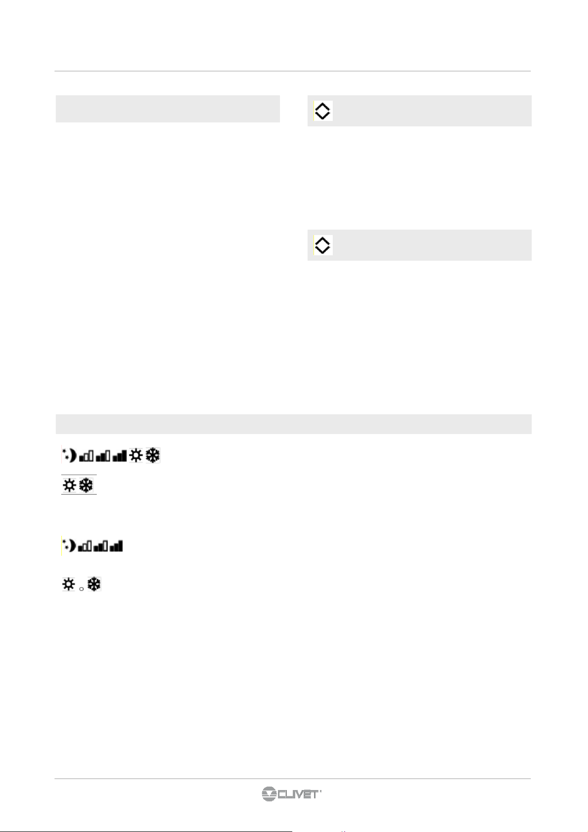
riscaldamento / raffreddamento
Tenere premuto il tasto Riscaldamento / Raffrescamento per
circa 2 secondi per commutare il modo di funzionamento tra
riscaldamento e raffrescamento visibile attraverso
l’accensione dei 2 simboli riscaldamento attivo o
raffrescamento attivo.
In riscaldamento il simbolo è acceso con setpoint superiore
alla temperatura ambiente, spenti entrambi con setpoint
inferiore.
In raffrescamento il simbolo è acceso con setpoint inferiore
alla temperatura ambiente, spenti entrambi con setpoint
superiore.
Nelle versioni a 4 tubi, con il sistema di regolazione
raffrescamento/riscaldamento automatico attivato
I'accensione contemporanea dei 2 simboli indica il
raggiungimento del setpoint (banda neutra).
Il lampeggio di uno dei 2 simboli indica che la temperatura
dell’acqua (calda o fredda) non è soddisfatta e comporta
l'arresto del ventilatore finché la temperatura non raggiunge
un valore adeguato a soddisfare la richiesta.
Se la temperatura dell'acqua non raggiunge un valore idoneo
al funzionamento richiesto, dopo 10minuti il comando va in
blocco, compare il simbolo di indicazione allarme E5.
Lo sblocco avviene automaticamente dopo 45 minuti o
manualmente premendo uno degli 8 tasti.
massima velocità di ventilazione
Tener premuto il tasto massima velocità di ventilazione.
L’attivazione della funzione viene segnalata dall'accensione
del relativo simbolo a display
Con questa modalità di funzionamento, si ottiene
immediatamente il massimo della potenza erogabile sia in
riscaldamento che in raffreddamento.
Una volta raggiunta latemperatura ambiente desiderata è
consigliabile selezionare uno degli altri 3 modi di
funzionamento per ottenere un miglior confort termico ed
acustico.
Premendo contemporaneamente i tasti ON stand-by e Temp
per 1 secondo si attiva il blocco locale di tutti i tasti, la
conferma è data dalla visualizzazione di Loc.
Tutte le regolazioni vengono inibite all’utente e alla pressione
di qualsiasi tasto compare Loc. Ripetendo la sequenza si
ottiene lo sblocco dei tasti.
E1 +
Guasto della sonda di temperatura ambiente (AIR).
E2 +
Guasto della sonda di rilevazione della temperatura dell’acqua
delle versioni a 2 tubi (H2) posizionata nella batteria
principale.
E3 +
Guasto della sonda di rilevazione della temperatura dell’acqua
fredda delle versioni a 4 tubi (H4).
E4 +
Problema al motore ventilatore (ad esempio inceppamento
dovuto a corpi estranei, guasto del sensore di rotazione,
azionamento del micro di protezione dovuto all’operazione di
pulizia del filtro).
E5 +
Se, dopo 10 minuti di funzionamento la temperatura
dell'acqua non ha raggiunto un valore idoneo al
funzionamento richiesto viene disattivato il contatto
dell'elettrovalvola e del consenso al chiller o alla caldaia
(Esempio 1: in riscaldamento con temperatura ambiente di
20°C e temperatura acqua inferiore ai 15°C. Esempio 2: in
raffrescamento con temperatura ambiente di 20°C e
temperatura acqua superiore ai 25°C).
Lo sblocco avviene automaticamente dopo 45 minuti o
manualmente premendo uno degli 8 tasti.
blocco tasti
allarmi
Page 25

6 - REGOLAZIONE
25
Impostazione sistema di regolazione
raffrescamento/ riscaldamento automatico
L’impostazione di questo tipo di regolazione permette al
comando di effettuare automaticamente la selezione del
raffrescamento o del riscaldamento escludendo la normale
selezione manuale.
Tale regolazione è particolarmente indicata per le versioni a 4
tubi.
Questo sistema di regolazione può essere attivato solo da un
tecnico installatore qualificato ed autorizzato.
Per attivare questa funzione mantenere premuto il tasto est/
inv (rif. A) per 10 secondi fino all’accensione simultanea dei
simboli raffrescamento (rif. C) e riscaldamento (rif. B).
Per ritornare nuovamente alla regolazione del funzionamento
solo raffrescamento o solo riscaldamento manuale premere il
tasto est/inv (rif. A) per 10 secondi fino allo spegnimento dei
simboli raffrescamento (rif. C) e riscaldamento (rif. B).
Premere nuovamente il tasto per selezionare la funzione
inverno.
Verificare il funzionamento del simbolo riscaldamento (rif. B)
(acceso con setpoint superiore alla temperatura ambiente,
spenti entrambi con setpoint inferiore).
Premere 1 volta il tasto est/inv per selezionare la funzione
estate. Verificare il funzionamento del simbolo raffrescamento
(rif. C) (acceso con setpoint inferiore alla temperatura
ambiente, spenti entrambi con setpoint superiore).
Questa selezione viene mantenuta anche in caso di
interruzione d’alimentazione.
Page 26

6.2 CONTROLLO A 4 VELOCITA'
26
6 - REGOLAZIONE
Il comando rende completamente autonoma la regolazione
della temperatura ambiente attraverso l’impostazione del
setpoint regolabile da 5 a 40°C, di una delle 4 velocità e la
selezione estate/inverno.
Essendo collegato alla sonda di rilevazione della temperatura
dell’acqua all’interno della batteria esegue la funzione di
minima temperatura invernale (30°C) e massima temperatura
estiva (20°C
).
display
Supersilent
velocità minima
velocità media
velocità massima
raffreddamento
Dopo un periodo di 20 secondi dall’ultima azione la luminosità
del pannello viene appositamente ridotta per aumentare il
confort nelle ore notturne e sul display viene visualizzata la
temperatura ambiente.
Alla pressione di un qualsiasi tasto viene ripristinata la
massima luminosità.
Tasti
aumenta temperatura impostata
diminuisce temperatura
Riscaldamento/Raffrescamento: consente di
commutare il modo di funzionamento tra
riscaldamento e raffrescamento (2 secondi)
mode
Consente di attivare l’apparecchio, di selezionare
una delle 4 velocità o di porlo in stand-by
off
(2 secondi).
riscaldamento
mode
Premere il tasto mode/off
Selezionare una delle 4 velocità di funzionamento premendo il
relativo tasto mode/off. In riscaldamento i simboli rimangono
accesi con setpoint superiore alla temperatura ambiente,
spenti con setpoint inferiore.
In raffrescamento i simboli sono accesi con setpoint inferiore
alla temperatura ambiente, spenti con setpoint superiore.
Stand-by: tenere premuto il tasto mode/off per circa 2
secondi . La mancanza di qualsiasi segnalazione luminosa dal
display identifica lo stato di "stand-by" (assenza di funzione).
Accensione / spegnimento
off
Riscaldamento/Raffrescamento
Tenere premuto il tasto Riscaldamento / Raffrescamento per
circa 2 secondi per commutare il modo di funzionamento tra
riscaldamento e raffrescamento visibile attraverso
l’accensione dei 2 simboli riscaldamento attivo o
raffrescamento attivo.
Il lampeggio di uno dei 2 simboli o indica che la temperatura
dell’acqua (calda o fredda) non è soddisfatta e comporta
l'arresto del ventilatore finché la temperatura non raggiunge
un valore adeguato a soddisfare la richiesta.
Page 27
6 - REGOLAZIONE
27
mode
Ad ogni pressione del pulsante del tasto mode/off corrisponde
la variazione della velocità del ventilatore tra supersilent,
minima, media e massima.
L’attivazione della funzione viene segnalata dall'accensione
del relativo simbolo a display
La velocità supersilent darà luogo ad una forte
deumidificazione in raffrescamento e ad un funzionamento
solo radiante (con ventilatore spento ed elettrovalvola
azionata) in riscaldamento.
Impostando la velocità massima si ottiene immediatamente il
massimo della potenza erogabile sia in riscaldamento che in
raffreddamento.
Una volta raggiunta latemperatura ambiente desiderata è
consigliabile selezionare uno degli altri 3 modi di
funzionamento per ottenere un miglior confort termico ed
acustico.
Regolazione velocità ventilatore
off
blocco tasti
Premendo contemporaneamente i tasti incremento e
decremento temperatura per 5 secondi si attiva il blocco
locale di tutti i tasti, la conferma è data dalla visualizzazione di
bL.
Tutte le regolazioni vengono inibite all’utente e alla pressione
di qualsiasi tasto compare bL.
Ripetendo la sequenza si ottiene lo sblocco dei tasti.
modificare temperatura impostata
Impostare con l'ausilio dei due tasti aumento e diminuzione il
valore di temperatura desiderato in ambiente visualizzato sui
2 digit del display.
Il range di regolazione va da 15 a 30 °C, con risoluzione di 1°
C, ma sono consentiti anche i valori fuori scala di 5°C e di 40°
C.
Impostare tali valori solo per brevi periodi e poi regolare la
selezione su un valore intermedio.
Il comando è molto preciso, portarlo sul valore desiderato ed
attendere che il comando esegua la regolazione in base alla
effettiva temperatura ambiente rilevata.
allarmi
Guasto della sonda di temperatura ambiente (AIR). Lampeggio dei 6 LED (allarme a riarmo
automatico).
Guasto della sonda di rilevazione della temperatura dell’acqua (H2) posizionata nella batteria
principale. Lampeggio dei 2 LED (possibile riarmo manuale).
Se la scheda rileva la sonda della temperatura dell’acqua, presente sull’apparecchio, l’avvio avviene
in condizioni normali. Se la sonda non viene connessa è possibile confermare il funzionamento privo
di sonda, premendo il pulsante Riscaldamento/Raffreddamento per 5 secondi
Problema al motore ventilatore (ad esempio inceppamento dovuto a corpi estranei, guasto del
sensore di rotazione, azionamento del micro di protezione griglia dovuto all’operazione di pulizia del
filtro). Lampeggio simultaneo dei 4 LED (allarme a riarmo automatico).
Richiesta di acqua (calda o fredda) non soddisfatta (sopra i 20°C in raffreddamento, sotto i 30°C in
riscaldamento).
Il LED della funzione selezionata lampeggia ed il ventilatore è arrestato finchè la temperatura
dell'acqua non raggiunge un valore adeguato a soddisfare la richiesta.
Page 28
6 - REGOLAZIONE
28
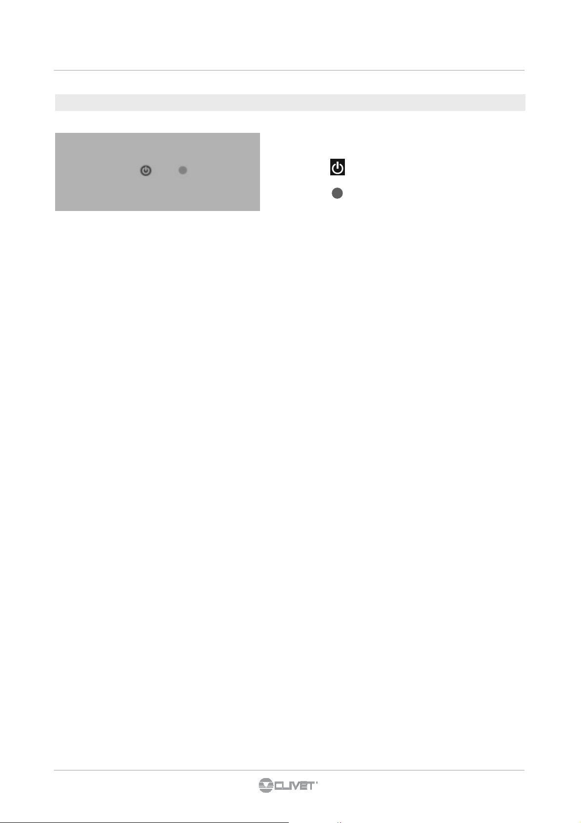
6.3 TASTIERA ON/OFF CON LED DI SEGNALAZIONE
Consente di attivare l'apparecchio o di metterlo
in condizione di attesa (tenere premuto 2 sec.)
Segnala il funzionamento dell’apparecchio.
Lampeggia in caso di anomalie.
Led di segnalazione
Acceso fisso Macchina connessa in rete e correttamente funzionante
Spento ventilconvettore spento o privo di alimentazione elettrica; nel primo caso alla successiva riaccensione del
comando remoto il ventilconvettore viene riacceso.
1 lampeggio + pausa Richiesta di acqua (calda o fredda) non soddisfatta. Comporta l'arresto del ventilatore finchè la temperatura
dell'acqua non raggiunge un valore adeguato a soddisfare la richiesta.
2 lampeggi + pausa Errore di comunicazione, il comando prevede uno scambio di informazioni continuo sulla linea seriale
RS485 con il controllo remoto , se questo viene a mancare per oltre 5 minuti viene visualizzato l'errore ed il
ventilradiatore/ventilconvettore viene disattivato.
3 lampeggi + pausa Bloccato per acqua non idonea, lo sblocco viene eseguito automaticamente dopo 45 minuti oppure
manualmente premendo due volte il tasto ON stand-by.
4 lampeggi + pausa Sonda acqua malfunzionante, tutte le uscite vengono spente fino alla risoluzione del problema.
5 lampeggi + pausa La segnalazione è associata ad un problema del motore ventilatore (ad esempio inceppamento dovuto a
corpi estranei, guasto del sensore di rotazione, azionamento del micro di protezione dovuto all’operazione
di pulizia del filtro).
Page 29
6 - REGOLAZIONE
29
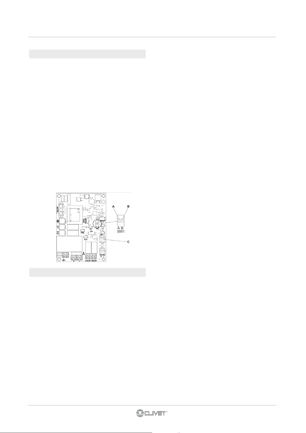
6.4 settaggio funzioni ausiliarie
Sulla scheda elettronica del comando sono posizionati due dip
-switch per la configurazione del funzionamento dell'apparec-
chio in funzione delle necessità.
Tramite il cursore A (fig. 9) si modifica la logica del funziona-
mento notturno:
• nella posizione ON viene inibita la ventilazione permetten-
do così alla macchina di riscaldare gli ambienti mediante
irraggiamento e convezione naturale, come avviene nei
radiatori tradizionali;
• in posizione OFF si ha invece il normale funzionamento
del ventilatore.
Posizionando il cursore B (fig. 9) in ON viene abilitata, solo in
raffrescamento, la ventilazione continua alla minima velocità
anche dopo il raggiungimento del set point (nella banda neutra) per consentire un più regolare funzionamento della sonda
di temperatura. Il passaggio alla condizione di riscaldamento
annulla la condizione;
con il cursore nella posizione OFF si disabilita tale funzione
6.5 spegnimento per lunghi periodi
In caso di spegnimenti stagionali o per vacanze procedere
come segue:
• Disattivare l'apparecchio.
• Posizionare l'interruttore generale impianto su Spento.
La funzione antigelo non è attiva
Page 30
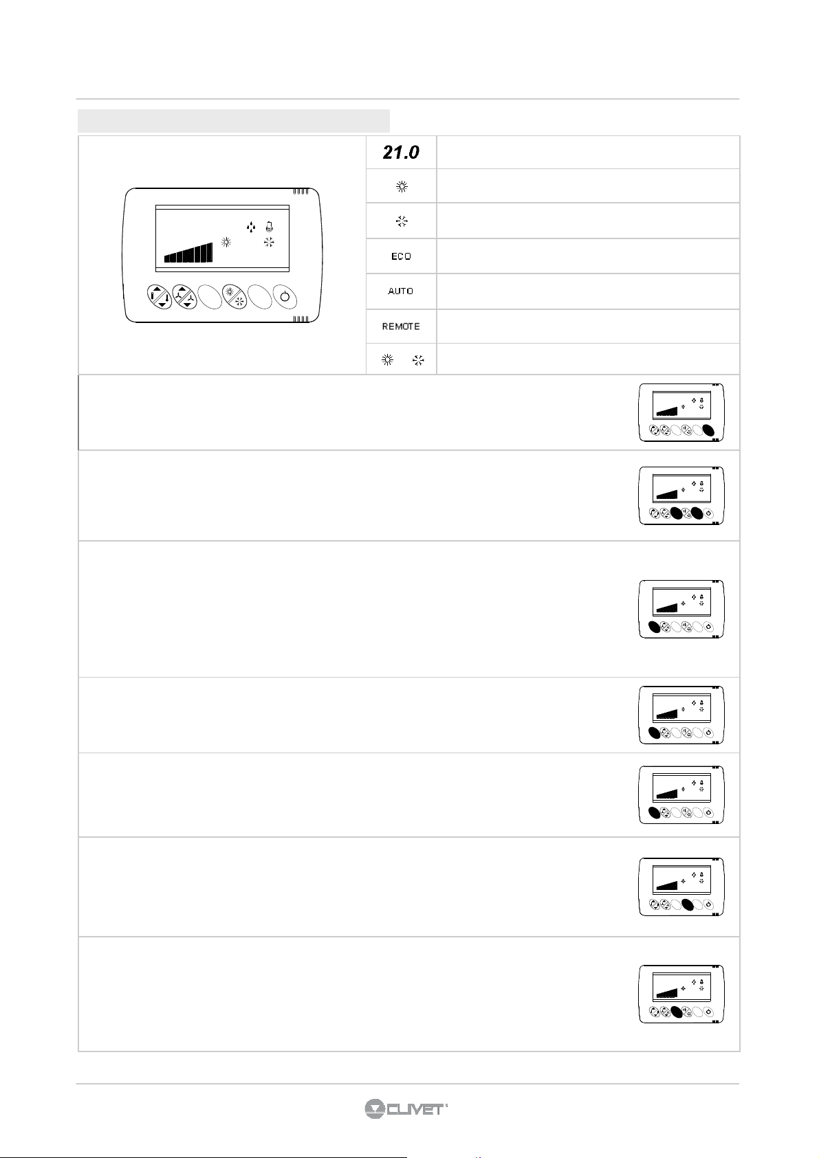
6.6 TERMOSTATO HID-T2 / T3 - OPZIONE
30
6 - REGOLAZIONE
set-point
unità in RAFFREDDAMENTO
21.0
REMOTE
ECO
AUTO
E
c
o
S
w
i
n
g
unità in RISCALDAMENTO
modalità ECO
visibile se la scelta del modo raffreddamento/riscaldamento
è AUTOMATICA
unità gestita da RETE
lampeggio : temperatura acqua fuori limiti
(ESTATE > 20°C , INVERNO < 30°C )
Accendere il termostato
tenere premuto per 4 sec il tasto ON OFF.
Se la funzione è gestita in modo remoto via ModBus non è possibile effettuare alcuna modifica (la dicitura
REMOTE inizia a lampeggiare).
Inserire / togliere il BLOCCO ANTIMANOMISSIONE
premere per 5 sec. i tasti ECO + SWING.
ll blocco è evidenziato dalla comparsa di 3 barrette orizzontali ogniqualvolta viene premuto un tasto qualsiasi.
Se la funzione è gestita in modo remoto via ModBus non è possibile effettuare alcuna modifica (la dicitura
REMOTE inizia a lampeggiare).
Modificare il set-point
premendo sulle frecce si aumenta o diminuisce il set-point del modo di lavoro in corso (riscaldamento, ECO
risc. , raffreddamento, ECO raff.
La differenza minima tra i due set point non può essere inferiore a 1°C e il valore è mantenuto automaticamente.
Ad esempio se con unità in raffreddamento si abbassa il set point estate fino a portarlo a ridosso del set inverno automaticamente quest’ultimo viene anch’esso abbassato.
Se la funzione è gestita in modo remoto via ModBus non è possibile effettuare alcuna modifica (la dicitura
REMOTE inizia a lampeggiare).
21.0
21.0
21.0
REMOTE
ECO
AUTO
S
E
w
c
i
n
o
g
REMOTE
ECO
AUTO
S
E
w
c
i
n
o
g
REMOTE
ECO
AUTO
S
E
w
c
i
n
o
g
Visualizzare la temperatura ambiente
premere a lungo entrambe le frecce del tasto SET, la temperatura ambiente viene visualizzata alternata alla
sigla “ t a ”.
Visualizzare l’umidità ambiente
SOLO PER TERMOSTATI HID-T3 CON SONDA UR
premere a lungo entrambe le frecce del tasto SET, la temperatura ambiente viene visualizzata alternata alla
sigla “ t a ”.
premere ancora a lungo il tasto set apparirà il valore di umidità alternato alla scritta “ ur “.
Passare dal modo RISCALDAMENTO al modo RAFFREDDAMENTO e viceversa
Se l’unità è in manuale la commutazione viene effettuata con il tasto relativo
Se a display è attiva la scritta “AUTO” il passaggio da un modo all’altro è gestito automaticamente dall’unità e
la pressione di questo tasto non ha alcun effetto.
Se la funzione è gestita in modo remoto via ModBus non è possibile effettuare alcuna modifica (la dicitura
REMOTE inizia a lampeggiare).
Mettere l’unità in modo ECO
Premere brevemente il tasto ECO.
Per ripristinare il funzionamento normale ripetere l’operazione.
Il set point ECO estivo è più alto del setpoint ESTATE, mentre il setpoint ECO invernale è più basso del setpoint INVERNO.
Se la funzione è gestita in modo remoto via ModBus non è possibile effettuare alcuna modifica (la dicitura
REMOTE inizia a lampeggiare).
21.0
21.0
21.0
21.0
REMOTE
ECO
AUTO
S
E
w
c
i
n
o
g
REMOTE
ECO
AUTO
S
E
w
c
i
n
o
g
REMOTE
ECO
AUTO
S
E
w
c
i
n
o
g
REMOTE
ECO
AUTO
S
E
w
c
i
n
o
g
Page 31

6 - REGOLAZIONE
31
FUNZIONAMENTO NOTTURNO
Premere brevemente il tasto ECO 2 volte : sul display compare NGT (NIGHT)
Vedere paragrafo 6.11.
Mettere l’unità in VENTILAZIONE MANUALE
ventilazione AUTOMATICA:
la velocità del ventilatore si autoregola in base alla temperatura ambiente
ventilazione MANUALE:
la velocità viene aumentata o diminuita dall’utente.
La pressione di uno dei due tasti freccia disattiva la ventilazione automatica.
Con ventilazione in manuale lampeggia la barra corrispondente alla velocità attiva.
Per ripristinare la ventilazione AUTOMATICA:
- aumentare la velocità fino alla massima
- una ulteriore pressione farà lampeggiare tutte le 8 barrette
- se non si compie nessuna ulteriore azione si torna alla ventilazione automatica.
Attenzione : nel passare al modo manuale l’unità potrebbe momentaneamente fermarsi
Se la funzione è gestita in modo remoto via ModBus non è possibile effettuare alcuna modifica (la dicitura
REMOTE inizia a lampeggiare).
SILENT
Premendo brevemente il tasto di ON-OFF si attiva la modalità silenziata. Per disattivarla si dovrà ripremere il
tasto di ON-OFF. Quando è attiva la modalità silenziata sul display del termostato appare la scritta SIL.
Quando si premono i tasti di variazione del Set la prima pressione visualizza il set corrente al posto della
scritta SIL.
Dopo un time-out di 10 sec se non vengono premuti i tasti di variazione del set-point si visualizza la scritta
SIL.
Se la funzione è gestita in modo remoto via ModBus non è possibile effettuare alcuna modifica (la dicitura
REMOTE inizia a lampeggiare).
21.0
NGT
21.0
21.0
REMOTE
ECO
AUTO
S
E
w
c
i
n
o
g
REMOTE
ECO
AUTO
S
E
w
c
i
n
o
g
REMOTE
ECO
AUTO
S
E
w
c
i
n
o
g
ALLARMI
Prima di resettare un allarme identificare e rimuovere la causa che lo ha generato .
Reset ripetuti possono determinare danni irreversibili . In caso di dubbio rivolgersi comunque ad un centro assistenza autorizzato .
La tabella riporta tutte le variabili gestibili dal sistema elettronico .
In funzione della configurazione di macchina e degli accessori presenti alcuni allarmi possono non essere significativi
RES allarme resistenze attivo.
FES allarme filtro.
BT1 allarme guasto sonda aria.
BT2 allarme guasto sonda acqua.
H2O allarme temperatura acqua non idonea.
EHH mancanza comunicazione/errato collegamento termostato.
SYS guasto interno al modulo di regolazione
Mot sensore del motore del ventilatore in allarme
RESET
auto
man (tasto SWING)
auto
auto
auto
auto
auto
auto
Page 32

6.7 TERMOSTATO HID-Ti2 - OPZIONE
32
6 - REGOLAZIONE
selezione modo di funzionamento
incrementa campo selezionato
decrementa campo selezionato
Stato ventilazione
Umidificazione attiva
Compressore attivo
MODI DI FUNZIONAMENTO
Funzionamento “normale” , HID-TI collegato al CLIVET-BUS :
REMOTE
OK conferma dato impostato / ON – OFF termostato
Unità in RAFFREDDAMENTO
Unità in RISCALDAMENTO
Gestione da ELFO CONTROL
Setpoint ECO abilitato
Unità sceglie automaticamente se
riscaldare o raffreddare
• il termostato HID visualizza lo stato di funzionamento dell’unità a cui è collegato
• misura periodicamente la temperatura/umidità dell’ambiente in cui è installato
• è possibile utilizzare i soli 4 tasti frontali ( programmazione utente ).
Funzionamento “nolink” , HID-TI non collegato al CLIVET-BUS
• il termostato viene alimentato dall’alimentazione ausiliaria ( deve essere presente la batteria )
• è possibile accedere ai pulsanti nascosti ad uso installatore
• è una modalità temporanea che permette di eseguire una “programmazione avanzata” dell’unità .
Accensione - Spegnimento
Per accendere e spegnere l’unità di regolazione, premere tasto OK in modo prolungato.
Lo stato spento viene indicato a display con la scritta OFF
Scelta del modo di funzionamento
Con la pressione di circa 3s del tasto
Con la pressione del tasto
riscaldamento → riscaldamento economico → raffreddamento → raffreddamento economico → ventilazione → riscaldamento
Con la pressione del tasto [OK] si conferma il modo visualizzato: i simboli diventano lampeggianti durante l’impostazione del modo,
poi si torna al funzionamento normale.
Se durante la programmazione del modo di funzionamento non si preme alcun tasto per circa 10s si ritorna al funzionamento norma-
le, senza modificare il modo di funzionamento.
Modifica del setpoint di regolazione
Nel funzionamento normale, nei modi di funzionamento che lo prevedono, è possibile modificare il setpoint di regolazione mediante i
tasti [▲] e [▼] rispettivamente per aumentare/diminuire con step di 0.1°.
Visualizzazione della temperatura ambiente
E’ possibile visualizzare la temperatura ambiente misurata dalla sonda a bordo termostato o da quella a bordo unità . Dallo stato di
funzionamento normale:
premere brevemente il tasto
premere nuovamente il tasto
premere il tasto [OK] per confermare la scelta: sul display lampeggerà la scritta tA per poi ritornare al funzionamento normale in cui
per qualche secondo la scritta tA sarà alternata al valore della temperatura ambiente.
E’ anche possibile tornare al funzionamento normale premendo invece del tasto OK il tasto
premere alcun tasto.
è possibile selezionare il modo di funzionamento desiderato con la seguente sequenza circolare :
: sul display compare la scritta Fan e la barra delle ventole
il display indica i simboli che definiscono il modo di funzionamento corrente .
: sul display compare solamente la scritta tA.
oppure attendendo circa 10s senza
Page 33

6 - REGOLAZIONE
33
Gestione della velocità delle ventole
Modo ventilazione
in modalità VENTILAZIONE non viene eseguita alcuna regolazione di temperatura
è possibile modificare la velocità delle ventole mediante i tasti ▲e ▼ .
Modi : Riscaldamento , Riscaldoamento-ECO , Raffreddamento, Raffreddamento-ECO
• premere brevemente il tasto : sul display compare la scritta “Fan” e la barra delle ventole
• mediante i tasti ▲e ▼ selezionare la velocità desiderata
• ritornare al funzionamento normale premendo il tasto OK
Se durante la modifica della velocità delle ventole non si preme alcun tasto per circa 10s si ritorna al funzionamento normale mantenendo le eventuali modifiche apportate.
Impostando la velocità delle ventole si passa dal funzionamento AUTOMATICO (dove la velocità delle ventole si autoregola in base
alla temperatura ambiente) ad un funzionamento MANUALE dove la velocità è definita dall’utente.
Per passare nuovamente al funzionamento automatico della ventilazione premere ripetutamente ▲ fino a visualizzare tutta la barra
lampeggiante.
Lo stato manuale delle ventole è indicato da una barra lampeggiante
L’impostazione della velocità delle ventole non è di tipo circolare
Modalità silenziata
Per attivare/disattivare la modalità silenziata premere brevemente il tasto OK.
La modalità silenziata è indicata a display con la scritta SIL
Blocco tastiera
Si utilizza per disabilitare le funzioni associate alla pressione dei tasti utente.
Estrarre il termostato dalla sede, premere il tasto [11]:
- compare a display la scritta bLC
- reinserire il termostato.
R
A
11109 8 7 6 5
- la scritta bLC lampeggerà fino al termine della procedura (qualche secondo)
Da questo istante in poi la pressione di un qualsiasi tasto non ha alcun effetto e produce momentaneamente a display la visualizzazione della stringa bLC.
Per tornare alla situazione normale, disinserendo il blocco tastiera ripetere l’operazione
Per il funzionamento con HID-Ti2 è necessario settare il parametro 96=1
FUNZIONAMENTO NOTTURNO non disponibile con termostato HID-Ti2
ALLARMI
Prima di resettare un allarme identificare e rimuovere la causa che lo ha generato .
Reset ripetuti possono determinare danni irreversibili . In caso di dubbio rivolgersi comunque ad un centro assistenza autorizzato .
La tabella riporta tutte le variabili gestibili dal sistema elettronico .
In funzione della configurazione di macchina e degli accessori presenti alcuni allarmi possono non essere significativi
RES allarme resistenze attivo.
FES allarme filtro.
BT1 allarme guasto sonda aria.
BT2 allarme guasto sonda acqua.
H2O allarme temperatura acqua non idonea.
EHH mancanza comunicazione/errato collegamento termostato.
SYS guasto interno al modulo di regolazione
Mot sensore del motore del ventilatore in allarme
RESET
auto
man (tasti ▲+ ▼)
auto
auto
auto
auto
auto
auto
Page 34

7 - MANUTENZIONE
34
7.1 GENERALITÀ
La manutenzione periodica è indispensabile per mantenere il
ventilconvettore sempre efficiente, sicuro ed affidabile nel
tempo.
Essa può essere effettuata con periodicità semestrale, per
alcuni interventi e annuale per altri, dal Servizio Tecnico di
Assistenza, che è tecnicamente abilitato e preparato e può
inoltre disporre, se necessario, di ricambi originali.
7.2 FREQUENZA INTERVENTI
La frequenza delle ispezioni deve essere almeno:
• annuale per le unità di solo raffreddamento estivo
• semestrale per le unità di raffreddamento e riscaldamento
La frequenza è comunque funzione del tipo di utilizzo.
Prevedere interventi ad intervalli ravvicinati in caso di utilizzi:
• pesanti (continuativi oppure altamente intermittenti, prossi-
mi ai limiti di funzionamento ecc)
• critici (servizio indispensabile).
7.3 PULIZIA ESTERNA
Prima di ogni intervento di pulizia e manutenzione scollegare
l’unità dalla rete elettrica spegnendo l’interruttore generale di
alimentazione.
Attendere il raffreddamento dei componenti per evitare il
pericolo di scottature.
Quando necessita pulire le superfici esterne del
ventilconvettore con un panno morbido e inumidito con
acqua .
Non usare spugne abrasive o detergenti abrasivi o corrosivi
per non danneggiare le superfici verniciate.
7.4 Estrazione celle filtranti nelle versioni con griglia
aspirazione ad alette
• estrarre la griglia anteriore sollevandola leggermente (fig.
7.1 rif. A) e ruotarla fino alla completa uscita dalla sua
sede (fig. 7.1 rif. B) ;
• estrarre il filtro (fig. 7.1 rif. C), tirando in senso orizzontale
verso l’esterno (fig. 7.1 rif. D).
7.5 Estrazione celle filtranti nelle versioni con pannello
aspirazione mobile
• Infilare le mani sotto le estremità del pannello mobile A
• Premere le linguette in plastica B
• Sollevare ed estrarre il pannello mobile C
• Estrarre il filtro D.
fig 7.2
7.6 Pulizia setti filtranti
• Aspirare la polvere dal filtro con un aspirapolvere ( rif. A)
• Lavare sotto acqua corrente, senza utilizzare detergenti o
solventi, il filtro (fig. rif. B), e lasciare asciugare.
• Rimontare il filtro sul ventilconvettore (fig. 7.4 rif. A), pre-
stando particolare attenzione ad infilare il lembo inferiore
(fig. 7.4 rif. B) nella sua sede (fig. 7.4 rif. C).
• E’ vietato l’uso dell’apparecchio senza il filtro a rete.
• L'apparecchio è dotato di un interruttore di sicurezza che
impedisce il funzionamento del ventilatore in assenza o
con pannello mobile mal posizionato.
• Dopo le operazioni di pulizia del filtro verificare il corretto
montaggio del pannello.
fig 7.3
fig 7.1
Page 35

7 - MANUTENZIONE
35
fig 7.4
7.7 Termine operazioni di pulizia
• Per le versioni con griglia ad alette infilare le due linguette (fig. 7.5 rif. A) nelle apposite asole (fig. 7.5 rif. B), farla ruotare ed aggan-
ciarla con un leggero colpo nella parte superiore.
• Per le versioni con pannello mobile appoggiarlo nella propria posizione parallelamente al frontale e premere fino a bloccarlo
fig 7.5
Page 36

7 - MANUTENZIONE
36
7.8 TABELLA DELLE ANOMALIE E DEI RIMEDI
Gli interventi devono essere eseguiti da un installatore qualificato o da un centro di assistenza specializzato.
Effetto
La batteria non raggiunge una
temperatura uniforme.
La ventilazione si attiva in ritardo rispetto
alle nuove impostazioni di temperatura o di
funzione.
La velocità di ventilazione aumenta o
diminuisce automaticamente.
L’apparecchio non attiva la ventilazione. Manca acqua calda o fredda nell’impianto. Verificare che la caldaia o il refrigeratore
La ventilazione non si attiva anche se nel
circuito idraulico è presente acqua calda o
fredda.
L’apparecchio perde acqua in funzione
riscaldamento.
Sono presenti formazioni di rugiada sul
pannello frontale.
Presenza di aria nel circuito interno
dell’apparecchio.
La valvola di circuito richiede un certo tempo
per la sua apertura e quindi per far circolare
l’acqua calda o fredda nell’apparecchio.
Il controllo elettronico agisce in modo di
regolare il miglior livello di comfort.
La valvola idraulica rimane chiusa Smontare il corpo valvola e verificare se si
Il motore di ventilazione è bloccato o
bruciato.
Il microinterruttore che ferma la ventilazione
all’apertura della griglia filtro non si chiude
correttamente.
I collegamenti elettrici non sono corretti. Verificare i collegamenti elettrici.
Perdite nell’allacciamento idraulico
dell’impianto.
Perdite nel gruppo valvole. Verificare lo stato delle guarnizioni.
La valvola termostatica integrata nel gruppo
di collegamento tra piastra e batteria non
chiude il flusso verso la parete.
Causa Rimedio
Sfiatare bene l’aria più volte
Attendere 2 o 3 minuti per l’apertura della
valvola del circuito.
Attendere la regolazione della temperatura
o in caso di necessità selezionare la
funzione silent.
d’acqua siano in funzione.
ripristina la circolazione dell’acqua.
Controllare lo stato di funzionamento della
valvola alimentandola separatamente a
220 V. Se si dovesse attivare, il problema
può essere nel controllo elettronico.
Verificare gli avvolgimenti del motore e la
libera rotazione della ventola.
Controllare che la chiusura della griglia
determini l’attivazione del contatto del
microinterruttore.
Controllare la perdita e stringere a fondo i
collegamenti .
Sostituire il raccordo che integra la valvola
termostatica nel gruppo superiore di
ingresso acqua.
Isolanti termici staccati. Controllare il corretto posizionamento degli
Sono presenti alcune gocce d’acqua sulla
griglia di uscita aria.
L’apparecchio perde acqua nella sola
funzione di raffreddamento.
L’apparecchio emette un rumore
eccessivo.
La ventola è sbilanciata. Lo sbilanciamento determina eccessive
Lampeggiano contemporaneamente tutti i
led.
In situazioni di elevata umidità relativa
ambientale (>60%) si possono verificare dei
fenomeni di condensa, specialmente alle
minime velocità di ventilazione.
La bacinella condensa è ostruita.
Lo scarico della condensa non ha la
necessaria pendenza per il corretto
drenaggio.
Le tubazioni di collegamento ed i gruppo
valvole non sono ben isolati.
La ventola tocca la struttura. Verificare le eventuali interferenze facendo
Filtri sporchi. Pulire i filtri e resettare la segnalazione
isolanti termoacustici con particolare
attenzione a quello anteriore sopra la
batteria alettata.
Appena l’umidità relativa tende a scendere
il fenomeno scompare. In ogni caso
l’eventuale caduta di alcune gocce
d’acqua all’interno dell’apparecchio non
sono indice di malfunzionamento.
Versare lentamente una bottiglia d’acqua
nella parte bassa della batteria per
verificare il drenaggio; nel caso pulire la
bacinella e/o migliorare la pendenza del
tubo di drenaggio. .
Controllare l’isolamento delle tubazioni
ruotare manualmente la ventola.
vibrazioni della macchina: sostituire la
ventola.
premendo per almeno 5 secondi il tasto
MODE.
Page 37

8 - DISMISSIONE
37
8.1 SCOLLEGAMENTO
Le operazioni di scollegamento devono essere effettuate da
tecnici qualificati.
• Evitare versamenti o perdite in ambiente.
• Prima di scollegare l’unità recuperare, se presenti :
- soluzioni incongelabili presenti nei circuiti idraulici
• In attesa di smantellamento e smaltimento l’unità può
essere immagazzinata anche all’aperto in quanto
intemperie e sbalzi di temperatura non provocano effetti
dannosi per l’ambiente, purché l’unità abbia i circuiti
elettrici, frigoriferi e idraulici integri e chiusi.
8.2 SMANTELLAMENTO E SMALTIMENTO
PER LO SMANTELLAMENTO E SMALTIMENTO, L’UNITÀ
DEVE ESSERE SEMPRE CONSEGNATA AI CENTRI
AUTORIZZATI.
In fase di smantellamento, il ventilatore, il motore e la batteria,
se funzionanti, potrebbero essere recuperati dai centri
specializzati per l'eventuale riutilizzo.
Tutti i materiali devono essere recuperati o smaltiti in
conformità alle norme nazionali vigenti in materia.
Per ulteriori informazioni sulla dismissione dell’unità contattare
la ditta produttrice
.
distributore, in appositi centri di raccolta.
Qualora lo smaltimento avvenga in concomitanza con la
fornitura di una nuova apparecchiatura elettrica ed elettronica
destinata ad un nucleo domestico, il prodotto potrà essere
ritirato direttamente dal distributore.
8.3 DIRETTIVA CE RAEE
Le unità che rientrano nella normativa in oggetto sono
contraddistinte dal simbolo a fianco.
Nell’ottica del rispetto dell’ambiente le nostre unità sono
prodotte in accordo alla Direttiva CE sui rifiuti di
apparecchiature elettriche ed elettroniche (RAEE).
Gli effetti potenziali sull’ambiente e sulla salute umana, dovuti
alla presenza di sostanze pericolose, sono riportati all’interno
del manuale d’uso e manutenzione nella sezione di rischi
residui.
Informazioni aggiuntive a quelle di seguito indicate, se
necessario, possono essere richieste sia al produttore/
distributore/importatore, in quanto responsabili della raccolta/
trattamento dei rifiuti derivanti da apparecchiature
contemplate dalla CE - RAEE, sia al negoziante da cui è stata
acquistata l’apparecchiatura oppure ai servizi locali preposti
alla raccolta rifiuti.
La Direttiva CE-RAEE prevede che lo smaltimento ed il
riciclaggio delle apparecchiature elettriche ed elettroniche, in
essa indicate, vengano obbligatoriamente gestiti tramite
un’apposita raccolta, in adeguati centri, separata da quella
adottata per lo smaltimento del rifiuto urbano misto.
L’utente ha l’obbligo di non smaltire l’apparecchiatura, alla fine
della vita utile della stessa, come rifiuto urbano, ma di
conferirla, come previsto dalle normative vigenti o indicato dal
Page 38

9.1 DIMENSIONALI
38
Versione a vista - 2 tubi
9 - INFORMAZIONI TECNICHE
Versione ad incasso - 2 tubi
(1) INGRESSO ACQUA SCAMBIATORE EUROKONUS 3/4
(2) USCITA ACQUA SCAMBIATORE EUROKONUS 3/4
(3) TUBO SCARICO CONDENSA Ø 14 MM
Page 39

9.1 DIMENSIONALI
39
Versione a vista - 4 tubi
9 - INFORMAZIONI TECNICHE
Versione ad incasso - 4 tubi
(1) INGRESSO ACQUA SCAMBIATORE EUROKONUS 3/4
(2) USCITA ACQUA SCAMBIATORE EUROKONUS 3/4
(3) TUBO SCARICO CONDENSA Ø 14 MM
Page 40

9 - INFORMAZIONI TECNICHE
40
Page 41

9 - INFORMAZIONI TECNICHE
41
Page 42

10 - RISCHI RESIDUI
42
Generalità
In questa sezione vengono segnalate le situazioni più comuni
che, non potendo essere controllate dal costruttore, potrebbero
dare origine a situazioni di rischio per cose o persone.
Zona pericolosa
E’ l’area nella quale può agire solo un operatore autorizzato.
La zona pericolosa è l’area interna delle unità, accessibile
soltanto mediante rimozione deliberata delle carenature o parti
di esse.
Movimentazione
Le operazioni di movimentazione, se effettuate senza tutte le
sicurezze necessarie e senza la dovuta prudenza, possono
causare la caduta o il ribaltamento dell’unità con conseguenti
danni, anche molto gravi, a cose, persone ed all’unità stessa.
Movimentare l’unità seguendo le istruzioni riportate sull’imballo,
nel presente manuale, e secondo le normative locali vigenti.
Installazione
Un’installazione errata dell’unità può causare perdite d’acqua,
accumulo di condensa, scosse elettriche, incendi, il cattivo
funzionamento o danni all’unità stessa.
Verificare che l’istallazione sia effettuata solo da personale
tecnico qualificato e che vengano seguite le istruzioni contenute
nel presente manuale e le normative locali vigenti.
L’installazione dell’unità in un luogo dove sono possibili, anche
sporadicamente, delle fughe di gas infiammabile ed il
conseguente accumulo di questi gas nell’area circostante l’unità
stessa, può essere causa di esplosioni ed incendi.
Verificare con cura il posizionamento dell’unità.
L’installazione dell’unità in un luogo non adatto a sostenerne il
peso e/o a garantirne un adeguato ancoraggio può causarne la
caduta e/o il ribaltamento, con conseguenti danni a cose,
persone o all’unità stessa.
Verificare con cura il posizionamento e gli ancoraggi dell’unità.
La facile accessibilità all’unità da parte di bambini, persone non
autorizzate o animali, può essere origine di incidenti ed
infortuni, anche gravi.
Installare l’unità in luoghi accessibili solo da personale
autorizzato e/o prevedere delle protezioni contro le intrusioni
nella zona pericolosa.
Rischi generici
Odore di bruciato, fumo, o altri segnali di anomalie gravi
possono indicare l’insorgere di situazioni che potrebbero
causare danni a cose, persone o all’unità stessa.
Sezionare elettricamente l’unità (sezionatore giallo-rosso).
Contattare il centro assistenza autorizzato per identificare e
risolvere il problema all’origine dell’anomalia.
Il contatto accidentale con batterie di scambio, compressori,
tubazioni di mandata o altri componenti può causare lesioni e/o
ustioni.
Indossare sempre un abbigliamento adeguato che comprenda
guanti protettivi per le operazioni all’interno della zona
pericolosa.
Operazioni manutenzione e riparazione effettuate da personale
non qualificato possono causare danni a cose, persone o
all’unità stessa.
Contattare sempre un centro di assistenza qualificato.
La mancata chiusura dei pannelli dell’unità, o la mancata
verifica del corretto serraggio di tutte le viti di fissaggio delle
pannellature può causare danni a cose, persone o all’unità
stessa.
Verificare periodicamente la chiusura di tutti pannelli ed il loro
corretto fissaggio.
Parte elettrica
Una linea di allacciamento alla rete elettrica non completa e/o
con cavi dimensionati non correttamente, e/o con dispositivi di
protezione inadeguati può causare shock da scosse elettriche,
intossicazioni, danni all’unità o incendi.
Effettuare tutti i lavori sull’impianto elettrico facendo riferimento
allo schema elettrico ed al presente manuale assicurando l’uso
di un impianto dedicato.
Un fissaggio non corretto del coperchio dei componenti elettrici
può favorire l’ingresso di polvere, acqua, ecc all’interno e di
conseguenza può causare scosse elettriche, danni all’unità o
incendi.
Fissare sempre bene il coperchio all’unità.
Le masse metalliche dell’unità, quando sono sotto tensione e
non sono collegate correttamente all’impianto di terra, possono
causare shock da scosse elettriche o la morte per folgorazione.
Curare in modo particolarmente attento l’esecuzione del
collegamento all’impianto di terra.
Il contatto con le parti in tensione accessibili all’interno dell’unità
dopo la rimozione dei ripari può causare shock da scosse
elettriche, ustioni o la morte per folgorazione.
Aprire e lucchettare il sezionatore generale prima di togliere i
ripari, e segnalare i lavori in corso con l’apposito cartello.
Il contatto con parti che potrebbero andare in tensione a causa
dell’avviamento dell’unità può causare shock da scosse
elettriche, ustioni o la morte per folgorazione.
Quando non è necessario avere tensione sui circuiti aprire il
sezionatore posto sulla linea di allacciamento dell’unità stessa,
lucchettarlo e dotarlo dell’apposito cartello di segnalazione.
Organi in movimento
Il contatto con le trasmissioni o con l’aspirazione dei ventilatori
può causare lesioni.
Prima di accedere all’interno dell’unità aprire il sezionatore
posto sulla linea di allacciamento dell’unità stessa, lucchettarlo
e dotarlo dell’apposito cartello di segnalazione.
Il contatto con i ventilatori può causare lesioni.
Prima di rimuovere le griglie di protezione o i ventilatori, aprire il
sezionatore posto sulla linea di allacciamento dell’unità stessa,
lucchettarlo e dotarlo dell’apposito cartello di segnalazione.
Parte idraulica
Difetti nelle tubature, negli allacciamenti o negli organi di
intercettazione possono dare origine a perdite o proiezioni
d’acqua con conseguenti danni a cose o cortocircuiti dell’unità.
Page 43

NOTE
43
Page 44

44
Page 45

45
ELFORoom2 3 - 5 - 11 - 15 - 17
Water terminal
Page 46

46
Dear Customer,
We congratulate you on choosing an ELFOSystem product, the air conditio-
ning system at annual cycle that offers the possibility in a sole system of
meeting all the heating, conditioning and domestic hot water needs.
Clivet is being working for years to offer systems able to assure the maximum
comfort for long time with high reliability, efficiency , quality and safety. The
target of the company is to offer advanced systems, that assure the best comfort, reduce the energy con-sumption, the installation and maintenance costs
for all the life-cycle of the system.
With this manual, we want to give you information that are useful in all the
phases: from the reception, to the installation and use until the disposal so
that a system so advanced offers the best procedure of installation and use.
Best regards and have a nice reading !
CLIVET Spa
The data contained in this bulletin is not binding and may be changed by the manufacturer without prior notice.All reproduction, even partial, is prohibited.
Page 47

INDEX
47
General
1
Reception
2
Positioning
3
Water connections
4
Electrical connections
5
Control
6
Maintenance
7
Decommissioning
8
Technical data
9
48
51
52
55
60
67
78
81
82
10
Residual risks
86
Page 48

1 - GENERAL
48
1.1 MANUAL
The manual provides correct unit installation, use and
maintenance.
Pay particolar attention to:
Warning identifies particularly important operations or
information .
Prohibited operations that must not be carried out, that
compromise the operating of the equipment or may cause
damage to persons or things.
• It is advisable to read it carefully so you will save time
during operations.
• Follow the written indications so you will not cause
damages to things and injuries people. The preliminary
information must be read prior to carrying out any of the
following operations.
1.2 GENERAL INSTRUCTIONS
Preliminaries
The positioning, hydraulic system, refrigerating, electrics and
the channelisation of the air must be determined by the
system designer in accordance with local regulations in force.
On the unit can operate only qualified personal , as
determined by the regulations in force.
Using the unit in case of breakdown or malfunction :
• voids the warranty
• may compromise the safety of the machine
• may increase time and repair costs.
Follow local safety regulations. .
Keep packing material out of children’s reach it may be
dangerous. .
Recycle and dispose of packing material in conformity with
local regulations. .
Risk situations
The unit has been designed and created to prevent injures to
people.
During designing it is not possible to plane and operate on all
risk situation.
Read carefully "Residual risk" section where all situation
which may cause damages to things and injuries to people
are reported.
Installation, starting, maintenance and repair required specific
knowledge; if they are carried out by inexperienced personnel,
they may cause damages to things and injuries people.
Intended use
Use the unit for cooling/heating water or a water and glycol
mix for air-conditioning only, within limits defined in the
technical bulletin and on this manual..
Any use other than intended does not involve the
manufacturer in any commitment or obligation. .
Installation
Verify that the electrical line characteristics are in compliance
with data quotes on the unit serial number label.
Maitenance
Plan periodic inspection and maintenance in order to avoid or
reduce repairing costs.
Turn the machine off before any operation.
Modification
All unit modifications will end the warranty coverage and the
manufacturer responsibility. .
Breakdown/Malfuction
Disable the unit immediately in case of breakdown or
malfunction. .
Contact a constructor certified assistance service.
Use original spares parts only.
User training
The installer has to train the user on :
• start-up / shutdown;
• set points change;
• standby mode;
• maintenance;
• what to do / what not to do in case of breakdown.
Data update
Continual product improvements may imply manual data
changes .
Visit manufacturer web site for updated data
1.3 INDICATIONS FOR THE USER
Keep this manual with the wiring diagram in an accessible
place for the operator.
Note the unit lable data so you can provide them at the assistance centre in case of intervention (see "Unit identification"
section).
Provide a machine notebook that allows any interventions
carried out on the machine to be noted and tracked making it
easier to suitably note the various interventions and aids the
search for any breakdowns.
In case of breakdown or malfunction:
.
• immediately deactivate the unit .
• contact a constructor certified assistance service.
• use original spares parts only
Ask the installer to format on:
• start-up / shutdown;
• set points change;
• standby mode;
• maintenance;
• what to do / what not to do in case of breakdown.
Page 49

1 - GENERAL
49
1.4 FUNDAMENTAL SAFETY RULES
Remember that some fundamental safety rules should be
followed when using a product that uses electricity and water,
such as:
• It is forbidden for the appliance to be used by children or
unassisted disabled persons.
• It is forbidden to touch the appliance with wet hands or
body when barefoot.
• It is forbidden to carry out any cleaning before having
disconnected the appliance from the electricity mains
supply by turning the system master switch to "OFF".
• It is forbidden to modify the safety or adjustment devices
or adjust without authorisation and indications of the
manufacturer.
• It is forbidden to pull, cut or knot the electrical cables
coming out of the appliance, even if it is disconnected
from the mains supply.
• It is forbidden to poke objects or anything else through the
inlet or outlet grills.
• It is forbidden to open the doors which access the internal
parts of the appliance without first turning the system
master switch to "OFF".
• It is forbidden to dispose of or leave in the reach of
children the packaging materials which could become a
source of danger.
• It is forbidden to climb onto the appliance or rest any
object on it.
• The external parts of the appliance can reach
temperatures of more than 70°C.
DANGER FROM BURNS -TAKE CARE WHEN TOUCHING
Serial number
It identifies uniquely each machine.
It identifies specific spare parts for the machine.
Assistance request
Note data from the serial number label and write them in the
chart on side, so you will find them easily when needed.
In case of intervention you have to provide data.
Series
Size
Serial number
Year of manufacture
Wiring diagram
1.6 UNIT VERSION
Vertical - Horizontal in view
Vertical - Horizontal uncased
1.5 UNIT INDENTIFICATION
Serial number label
The serial number label is positioned on the unit and allows to
indentify all the unit features.
It has not to be removed for any reason.
It reports the regulations indications such as:
• machine type,
2
series → ELFOROOM
size → 3 ( o 5 o 11 o 15 o 17)
• Serial number
Axxxxxxxxxxx
• year of manufacture
• wiring diagram number
• electrical data
• manufacturer logo and address
Page 50

1 - GENERAL
50
1.7 ACCESSORIES
Each accessory is accompanied by its instruction leaflets for assembly.
• KASPX
Return plenum kit
•
GMX
Outlet grille
•
GRA1X
Air outflow grille
•
PR90MX
90° air outlet plenum
•
PMSTX
Telescopic upper supply plenum kit
•
KV3B4X
3-way valve kit with electrothermal head and balancing for 4-pipe system (available only with options:B4T)
• KV3VBX
3-way valve kit with electrothermal head and balancing
•
HIDE1X
Remote control with 3 position switch + on/off for wall installation (available only with options: 3V010)
•
HIDE2X
Remote control with E/I +3V +on/off for wall installation (available only with options: 3V010)
•
HIDE3X
Plurifunctional remote control for wall installation (available only with options: 3V010)
•
HID-T2X
HID-T2 electronic ambient control
(external, temperature only)
• HID-T3X
HID-T3 electronic ambient control
(external, temperature and humidity)
• HID-TI2X
HID-TI2 flush-mounted electronic ambient control
(wall-mounted, temperature only)
• KCMDX
Motor connection cables for unit with couplings on the right
•
PCIX
Uncased closure panel
•
BACKVX
Painted back panel for cased version
•
CSFIX
Formwork for uncased installation
•
FXPPX
Floor fixing bracket kit
•
KPDX
Plinth kit
Page 51

2 - RECEPTION
51
2.1 PRELIMINARY INFORMATION
General
Operate in compliance with safety regulations in force .
For detailed information (dimensions, weight, technical
characteristics etc.) please refer to the “Technical
information” section.
Use single protection devices : gloves, glasses ecc.
Stocking
Observe external packing instructions .
Handling
Verify unit weight and handling equipment lifting
capacity .
Identify critical points during handling (disconnected
routes, flights, steps, doors).
Verify the position of the barycentre in the Technical
information - DIMENSIONS section.
Before handling verify that the unit keeps its balance.
Packing removing
Be careful not to damage the unit.
Recycle and dispose of packing material in conformity
with local regulations.
2.3 HANDLING
Do not leave loose packages during the transport
Do not handle the unit alone
Do not tramble
2.2 DELIVERY CONTROL
Before accepting the delivery you have to check:
• That the unit hasn’t been damaged during tran-
sport.
• Check that the materials delivered correspond
with that indicated on the transport document
comparing the data with the identification label
positioned on the packaging.
In case of damage or anomaly:
• Write down on the transport document the da-
mage you found and quote this sentence:
"Conditional acceptance — clear evidence of
deficiencies/damages during transport".
• Contact supplier and the carrier by fax and regi-
stered mail with advice of receipt.
Any disputes must be made within the 8 days following
the delivery. Complaints after this period are invalid.
Page 52

3 - POSITIONING
52
3.1 PRELIMINARY INFORMATION
General
Operate in compliance with safety regulations in force.
For detailed information (dimensions, weight, technical
characteristics etc.) please refer to the TECHNICAL
INFORMATION section.
Use single protection devices : gloves, glasses ecc.
During positioning consider these elements :
• technical spaces required for the machine and system
• place where the machine will be installed
• electrical connections
• water connections
• air / aeraulic ducts
Do not considerer these elements could decrease
performances and operational life of the unit.
3.2 FUNCTIONAL SPACES
Functional spaces are designed to:
• guarantee good unit operation
• Carry out maintenance operations
• protect authorized operators and exposed people.
Respect all functional spaces indicated in the figure.
3.3 POSITIONING
Avoid installing the unit in proximity to:
• positions subject to exposure to direct sunlight;
• in proximity to sources of heat;
• in damp areas or places with probable contact with water;
• in places with oil fumes
• places subject to high frequencies.
Make sure that :
• the wall on which the unit is to be installed is strong
enough to support the weight;
• the part of the wall interested does not have pipes or
electric wires passing through;
• the interested wall is perfectly flat;
• there is an area free of obstacles which could interfere
with the inlet and outlet air flow;
• the installation wall is preferably an outside perimeter wall
to allow the discharge of the condensation outside;
• in case of ceiling installation the airflow is not directed
towards persons.
If provided a wall-mounted ambient thermostat - OPTION - :
Install the room thermostat far from heat sources (radiators,
sunbeam, kitchens), from doors , windows etc.
OK
1,5 m
Page 53

3 - POSITIONING
53
3.4 INSTALLATION
The following descriptions of the various mounting phase and the relative designs refer to a version of the machine with fixtures on the
left. The operations for the mounting of machines with fixtures on the right are exactly the same
Only the images are to be considered as a mirror image.
3.5 SIDE OPENING
.
• lift A
• unscrew B
• move to the left C
• lift C
3.6 HORIZONTAL OR CEILING INSTALLATION
• lift A
• unscrew B
• move to the right D
• lift D
• Using the paper template, trace on the ceiling the position of the two fixing brackets and the two rear screws.
• Using a suitable drill, make the holes and insert the toggle bolts (2 for each bracket) (fig. 3.1 ref. A); fix the two brackets (fig. 3.1
ref. B). Do not over-tighten the screws.
• Position the machine on the two brackets, keeping it in position and then fix the two screws into the rear toggle bolts (fig. 3.1 ref.
C), one on each side.
• Make sure that there is sufficient inclination of the unit towards the drainage pipe to facilitate the water drainage (fig. 3.1 ref. D).
• Fully tighten all 6 fixing screws.
fig 3.1
Page 54

3 - POSITIONING
54
3.7 VERTICAL FLOOR OR WALL INSTALLATION
When floor mounting with support pins, respect the min. ground height of 80mm., for the pin mounting and refer to the individual
instructions leaflets supplied and the relative manual
• Using the paper template, trace the position of the two fixing brackets on the wall (fig. 3.2).
• Use a suitable drill to make the holes with and insert the toggle bolts (2 for each bracket) (fig. 3.3 ref. A); fix the two brackets (fig.
3.3 ref. B). Do not over-tighten the screws so that the brackets can be adjusted with a spirit level (fig. 3.4).
• Fully tighten the four screws to block the two brackets.
• Check the stability by manually moving the brackets to the right and to the left, up and down.
• Mount the unit, checking that it fits correctly onto the brackets and checking that it is stable (fig. 3.5).
fig 3.2 fig 3.3
fig 3.4
fig 3.5
Page 55

4 - WATER CONNECTIONS
55
4.1 PIPELINE DIAMETER
Inlet water : EUROKONUS 3/4
Outlet water : EUROKONUS 3/4
Condensate discharge : Ø 14 mm (internal diameter)
For the position of the pipeline and the wall fixings, refer to the
designs shown in the following sections, based on the specific
configuration.
4.2 CONNECTIONS
The choice and sizing of the hydraulic lines must be made by
an expert who must operate according to the rules of good
technique and the laws in force.
Insulate the water lines / In the figure are indicated the optional components
To make the connections:
• position the hydraulic lines
• tighten the connections using the “spanner and counter
spanner” method ( ref. B)
• check for any leaks of liquid
• coat the connections with insulating material ( ref. C).
The hydraulic lines and joints must be thermally insulated.
Avoid partially insulating the pipes.
Do not over-tighten to avoid damaging the insulation.
Use hemp and green paste to seal the threaded connections;
the use of Teflon is advised when there is anti-freeze in the
hydraulic circuit.
4.3 CONDENSATION DISCHARGE
The condensation discharge network must be suitably sized
(minimum inside pipe diameter 16 mm) and the pipeline
positioned so that it keeps a constant inclination, never less
than 1%.
• In the vertical installation, the discharge pipe is connected
directly to the discharge tray, positioned at the bottom of
the side shoulder underneath the hydraulic fixtures.
• In a horizontal installation the discharge tube is connected
to the one already present on the machine.
If possible, make the condensation liquid flow directly in a
gutter or a “rainwater” discharge.
When discharging directly into the main drains, it is advisable
to make a siphon to prevent bad smells returning up the pipe
towards the room. The curve of the siphon must be lower
than the condensation collection bowl.
If the condensation needs to be discharged into a container, it
must be open to the atmosphere and the tube must not be
immerged in water to avoid problems of adhesiveness and
counter-pressure that would interfere with the normal outflow.
If there is a height difference that could interfere with the
outflow of the condensation, a pump must be mounted
(accessory kit):
• in a vertical installation mount the pump under the lateral
drainage tray;
• in a horizontal installation the pump position must be
decided according to the specific requirements.
In any case, consult the specific instructions in the
condensation discharge pump kit.
However, on completion of the installation it is advisable to
check the correct outflow of the condensation liquid by slowly
pouring about ½ l of water into the collection tray in about 510 minutes.
Page 56

4 - WATER CONNECTIONS
56
4.3.2 Condensation discharge VERTICAL version 4.3.1 Condensation discharge HORIZONTAL version
To mount the horizontal bowl refer to the instructions in kits.
• check that the "L" pipe and the flexible rubber hose are
correctly connected to the bowl (fig. 4.1 rif. A).
• slide in the side of the machine keeping the pipe in
position up against the front grill.
• fully close the side checking that the pipe remains blocked
in the special grove on the side (fig. 4.2 rif. B).
For the horizontal installation carefully note the following
precautions:
• make sure that the machine is installed perfectly
level or with a slight inclination towards the
condensation discharge;
• insulate carefully the inflow and outflow pipes up to
the machine union to prevent any drops of
condensation outside the same collection bowl;
• insulate the bowl condensation discharge pipe
along all of its length.
fig 4.1
• Connect to the condensation collection tray discharge
union (fig. 4.3 rif. A) a pipe for the outflow of the liquid (fig.
4.3 rif. B) blocking it adequately.
• Check that the drip-collector extension (fig. 4.3 ref. C) is
present and correctly installed.
fig 4.3
4.4 FIXTURE ROTATION
The operations described and the relative images refer to a
machine with fixtures on the left on which the fixtures on the
right side must be rotated.
If there is a machine available with right side fixtures that
require rotation to the left, the sequence of the operations is
the same, only the images are a mirror image.
To connect the motor to the control kit, use the special
cabling optional.
fig 4.2
4.4.1 Dismouting panels
• Dismount the upper grill (fig. 4.4 ) unscrewing the two
fixing screws (fig. 4.4 ).
• On the left-hand side loosen the screw that fixes the left
panel, then move it slightly to the left and lift it up.
• On the opposite side lift the cover covering the screw and
unscrew it.
• Move the side panel slightly to the right and lift it.
• Remove the lower front grill (fig. 4.5 rif. A).
• Loosen the screws (fig. 4.5 ref. B-D) fixing the front panel
(fig. 4.5 ref. E) and dismount it.
Page 57

4.4.2 Dismounting control panel
57
4 - WATER CONNECTIONS
• Position the system master switch to OFF.
• Dismount the door that accesses the collector units (fig.
20 ref. A) unscrewing the two fixing screws (fig. 4.6 ref. B).
• Dismount the control panel (fig. 4.6 ref. C) unscrewing the
two fixing screws (fig. 4.6 ref. D).
• Unplug the control board (fig. 4.6 ref. E).
• Unplug the connectors of the electrical connections.
• Remove the cables inside the machine and re-insert them
from the opposite side.
fig 4.4
• For the motor connection, use the special cable for right
hand fixtures , available as an accessory.
• Invert the mounting positions of the door (fig. 4.6 ref. A) with
the control panel (fig. 4.6 ref. C) and remount them in their
respective positions.
• Dismount the condensation collection tray (fig. 4.6 ref. F)
and remount it on the opposite side with the relative fixing
screws (fig. 4.6 ref. G).
fig 4.5
The insulating panel must be in the shown position , otherwise the battery is not crossed by air
Page 58

fig 4.6
58
4 - WATER CONNECTIONS
4.4.3 Coil rotation for connections on RIGHT
• loosen the four screws that fix the lower exchanger (fig.
4.7 rif. C);
• remove the battery water probe;
• remove the exchanger (fig. 4.7 rif. F);
• remove the drip-collector extension from the central tray
(fig. 4.7 rif. D);
• on the opposite side remove the plug on the condensation
evacuation hole (fig. 4.7 rif. E);
• loosen the central condensation collection tray fixing
screw (fig. 4.7 rif. G), move the tray and rest it on the
fig 4.7
opposite side so that the fixture mouth for the dripcollector
extension comes out of the structure, and block the tray with
the screw previously removed;
• re-insert the drip-collector extension and the plug on the
opposite side;
• rotate the exchanger moving the fixtures to the opposite
side, and reinsert it on the machine;
• tighten all the fixing screws of the exchanger
• When all the operations described have been completed,
remount all the components dismounted previously following
the dismounting operations in the opposite order.
Page 59

4 - WATER CONNECTIONS
59
4.5 MOUNTING FRONT GRILL SAFETY SUPPORT
In the case in which the coolerconvector is installed in a
horizontal position, to guarantee the safety of the cleaning/
filter replacement operations it is obligatory that the two
clamps, in the supplied bag together with the instruction
manual and the accessories, are mounted by the installer.
• Separate the two clamps (fig. 4.8 rif. A);
fig 4.8
• open the front grill and completely unscrew the fixing
screws on the springs (fig. 4.8 rif. B);
• fix the two clamps, blocking them by retightening the screws
(fig. 4.8 rif. B);
• fix the other part of the clamp to the grill using the supplied
screws (fig. 4.8 rif. C);
• Close the grill.
4.6 FILLING THE SYSTEM
When starting up the system, make sure that the hydraulic
unit lockshield is open. If there is no electric power and the
thermo-valve has already been powered use the special cap
to press the valve stopper to open it.
• Open all the system interception devices (manual or
automatic);
• Start the filling by slowly opening the system water filling
tap;
• For the models installed in a vertical position, take a
screwdriver and act on the highest breather of the battery
(fig.4.9 rif.A);
fig 4.9
• for appliances installed in a horizontal position, act on the
highest positioned breather (fig.4.9 rif.B);
• When water starts coming out of the breather valves of the
appliance, close them and continue filling until reaching the
nominal value for the system.
• Check the hydraulic seal of the gaskets.
• It is advisable to repeat these operations after the appliance
has been running for a few hours and periodically check the
pressure of the system.
Page 60

5 - ELECTRICAL CONNECTIONS
60
5.1 PRELIMINARY INFORMATION
The characteristics of the electrical lines must be determined
by specialized personnel able to design electrical installations;
moreover, the lines must be in conformity with regulations in
force.
The protection devices of the unit power line must be able to
stop of presumed short circuit current, whose value must be
determined in function of system characteristic
The power cables and the protection cable section must be
define in accordance with the characteristics of the protections
adoptee.
All electrical operations should be performed by trained
personnel having the necessary requisites by the regulations
in force and being informed about the risks relevant to these
activities.
Operate in compliance with safety regulations in force.
5.2 ELECTRICAL DATA
The serial number label reports the unit specific electrical
data, included any electrical accessories .
The electrical data indicated in the technical bulletin and in the
manual refer to the standard unit, accessories excluded.
Refer to the electrical data report on the serial number label.
6. Before power the unit, make sure that all the protections
that were removed during the electrical connection work
have been restored.
5.4 SIGNAL / DATA
Do not overpass the maximum power allowed, which varies,
according to the type of signal.
Lay the cables far from power cables or cables having a different tension and that are able to emit electromagnetic disturbances.
Do not lay the cable near devices which can generate electromagnetic interferences.
Do not lay the cables parallel to other cables; cable crossings
are possible, only if laid at 90°.
Connect the screen to the ground, only if there aren’t disturbances
Guarantee the continuity of the screen during the entire extension of the cable.
Respect impendency, capacity and attenuation indications.
5.5 ACCESS TO THE ELECTRICAL PANEL
Open the sides: instructions at paragraph 3.5.
serial
number
label
F.L.A. full load ampere
Full load current at max admissible conditions
F.L.I. Full load input
Full load power input
( at max. admissible condition )
N° WIRING DIAGRAM
POWER SUPPLY
FLA (A)
FLI (kW)
5.3 CONNECTIONS
1. Refer to the unit electrical diagram (the number of the
diagram is shown on the serial number label)
2. Verify that the network has characteristics conforming to
the data shown on the serial number label
3. Before starting work, verify that the sectioning device at
the start of the unit power line is open, blocked and equipped with cartel warning
4. Primarily you have to realize the earthing connection
5. Shelter the cables using adequate measure fairleads
Page 61

5 - ELECTRICAL CONNECTIONS
61
5.6 Connection with room thermostat mounted on- board
4 tube : Y1 + Y2
2 tube : Y1
BOILER Heating go-ahead output (boiler-caldaia)
free contact max 1A
CHILLER Cooling go-ahead output (chiller)
free contact max 1A
SW2 Remote ON / OFF
H2 Water temperature probe (4T → heating)
2T → cooling / heating
H4 Water temperature probe (4T → cooling)
S1 Grill safety micro-switch
Y1 Water solenoid valve (4T → heating)
(2T → heating / cooling)
Y2 Water solenoid valve (4T → cooling)
Page 62

5 - ELECTRICAL CONNECTIONS
62
5.7 Connection to HID-Txx electronic room thermostat
4 tube : Y1 + Y2
2 tube : Y1
BOILER Heating go-ahead output (boiler-caldaia)
free contact max 1A
CHILLER Cooling go-ahead output (chiller)
free contact max 1A
SW2 Remote ON / OFF
H2 Water temperature probe (4T → heating)
2T → cooling / heating
HID-T2 / T3 THERMOSTAT
H4 Water temperature probe (4T → cooling)
S1 Grill safety micro-switch
Off = switched off ventilation at setpoint satisfied
Y1 Water solenoid valve (4T → heating)
(2T → heating / cooling)
Y2 Water solenoid valve (4T → cooling)
Radiant option: see 5.6
HID-iI2 THERMOSTAT
Page 63

5 - ELECTRICAL CONNECTIONS
63
5.8 MINI-NETWORK - MAX 9 ELFORoom2
* 120 Ω network termination resistance - customer care
5.9 ELFOSystem GAIA Edition
1. Bus RS485
2. ELFOControl Home
3. GAIA
4. ELFOFRESH
5. Zone with 2 ELFOROOM
controls both terminals
6. Zone with 1 ELFOROOM
that controls the terminal
7. ELFOROOM
both terminals
8. ELFOROOM
2
2
with keypad and HID-T3 thermostat that controls
2
with built-in thermostat
2
with keypad and HID-Ti2 thermostat
2
with keypad and HID-Ti2 thermostat
Page 64

5 - ELECTRICAL CONNECTIONS
64
5.10 Connection with 4-speed electronic control
2 PIPE SYSTEM
AIR Air temperature probe
H2 Water temperature probe
S1 Grill safety micro-switch
Y1 Water solenoid valve
Page 65

5.11 Thermostats connections
65
5 - ELECTRICAL CONNECTIONS
Command enable 3 speed
HID-E1 thermostat - 2 pipe system
HID-E2 thermostat - 4 pipe system
HID-E2 thermostat - 2 pipe system
Page 66

5 - ELECTRICAL CONNECTIONS
66
HID-E3 thermostat - 4 pipe system
H2O water temperature probe
HID-E3 thermostat - 2 pipe system
H2O water temperature probe
0-10V enable command
10v = fan 1400 rpm
1v = fan 450 rpm
<1v = fan off
Page 67

6.1 BUILT-IN ELECTRONIC THERMOSTAT
67
6 - CONTROL
display keys
display
Automatic function
Silent function
Maximum ventilation speed
Night function
Heating
Cooling
Webserver supervision
Active alarm
ON / Standby
Keep the ON standby button pressed for about 2 seconds.
The lack of a warning light indicates the "stand-by" status (no
function).
When the control is set to this operating mode it guarantees an
anti-freeze security.
If the room temperature falls below 5°C the boiler condensation
and hot water solenoid valves are activated.
automatic regulation of the ventilation speed
Press and hold the AUTO key.
When the function is activated, the relative symbol on the
display turns on
The ventilation speed is adjusted automatically between a
minimum value and a maximum value, according to the actual
gap between the ambient temperature and the selected
setpoint based on a PI algorithm.
keys
ON / Standby
Increase set temperature
Decrease set temperature
Automatic regulation of the ventilation speed
Night function
Minimum ventilation speed
Heating / Cooling
Maximum ventilation speed
temperature change set
Use the two buttons to set the desired room temperature
which is displayed on the 3 digit display.
The adjustment range is from 16 to 28 °C; with resolution is
0.5 °C, but are also permitted off-scale values of 5 °C
and 40 °C.
Only set these values for short periods and then set the
selection to an intermediate value.
The command is very precise, set it to the desired value and
wait until the command has made the adjustment based on
the room temperature detected.
Page 68

6 - CONTROL
68
night functioning
Keep the night functioning button.
When the function is activated, the relative symbol on the
display turns on.
Selecting this operating mode, the ventilation speed is limited
to a much lower value and the set temperature is
automatically adjusted as follows:
- reduced by 1° C after one hour and a further degree after 2
hours in the heating function.
- Increased by1°C after one hour and a further degree after 2
hours in the cooling function.
minimum ventilation speed
Keep the minimum ventilation speed button.
When the function is activated, the relative symbol on the
display turns on.
The ventilation speed is limited to a lower value.
heating / cooling
Press and hold the Heating / Cooling key for about 2 seconds
to switch the operating mode between heating and cooling.
This is reported by the fact that the 2 symbols, active heating
or active cooling, turn on.
In heating mode, the symbol is ON with setpoint higher than
the room temperature, both OFF with lower setpoint.
In cooling mode, the symbol is ON with setpoint lower than the
room temperature, both OFF higher with setpoint.
In the versions with 4 pipes, with the automatic heating/
cooling adjustment on, if the 2 symbols turn on
simultaneously, this means that the setpoint has been
reached (neutral band).
If one of the 2 symbols is flashing, this means that the (hot or
cold) water temperature has not been reached and the fan
stops until the temperature reaches a value that is suitable to
meet the request.
If the water temperature does not reach a suitable value in
relation to the required operating mode, after 10 minutes the
control is blocked and the symbol indicating the E5 alarm
appears.
This is automatically unlocked after 45 minutes or manually by
pressing one of the 8 keys.
maximum ventilation speed
Keep the maximum ventilation speed button.
When the function is activated, the relative symbol on the
display turns on.
With this operating mode, maximum power is obtained
immediately both in heating and cooling.
Once the desired ambient temperature has been reached, we
recommend selecting one of the other 3 operating modes to
achieve greater thermal and acoustic comfort.
By pressing the ON stand-by and Temperature keys together
for 1 second, this activates the local block of all the keys.
This is confirmed by the fact that the word Loc. is displayed.
The user is prevented from using all the adjustments and
pressing any key and the display shows Loc. The keys are
unlocked by repeating the sequence.
E2 +
Failure affecting the water temperature probe of the versions
with 2 pipes (H2) located in the main coil.
E3 +
Failure affecting the cold water temperature probe of the
versions with 4 pipes (H4).
E4 +
Problem affecting the fan motor (for instance a jam due to
foreign bodies, a rotation sensor failure, activation of the
protective micro switch due to the fact that the filter is being
cleaned).
E5 +
If after 10 minutes of operation, the water temperature has not
reached a value suitable in relation to the required operating
mode, the contact of the solenoid valve and the enabling input
to the chiller or the boiler is disabled (Example 1: in heating
mode with an ambient temperature of 20°C and water
temperature below 15°C. Example 2: in cooling mode with an
ambient temperature of 20°C and water temperature above
25°C).
This is automatically unlocked after 45 minutes or manually by
pressing one of the 8 keys.
keys lock
alarms
Page 69

6 - CONTROL
69
Setting automatic cooling/ heating regulation system
When set to this condition the control can automatically
choose between cooling or heating, excluding the normal
manual selection.
This setting is particularly useful for the 4-pipe versions.
This regulation system can only be activated by an authorised
installer or qualified technician.
To activate this function, keep the sum./ win. button (ref. A)
pressed for 10 seconds until of the cooling symbols (ref. C)
and heating (ref. B) light up simultaneously.
To return again to the manual cooling only or heating only
condition press the sum/win button (ref. A) for 10 seconds
until of the cooling symbols (ref. C) and heating ( ref. B)
switch off.
Press the button again to select the winter function.
Check the functioning of the heating symbol (ref. B) (alight
when the setpoint is higher than the room temperature, both
switched off when the setpoint is lower).
Press the sum/win button once to select the summer function.
Check the functioning Check the functioning of the cooling
symbol (ref. C) (alight when the setpoint is lower than the
room temperature, both switched off when the setpoint is
higher).
This selection will be maintained even if there is a power black
-out.
Page 70

6.2 4 SPEED CONTROL
70
6 - CONTROL
The control makes the control of the ambient temperature fully
autonomous by setting the setpoint that can be adjusted from
5 to 40°C, one of the 4 speeds and the summer/winter
selection.
As it is connected to the water temperature probe inside the
coil, it performs the minimum winter function (30°C) and
maximum summer function (20°C
Supersilent
Minimum speed
Medium speed
Maximum speed
Cooling
).
display
After about 20 seconds from the last action, the panel's
brightness is suitably reduced to increase comfort during the
night and the ambient temperature is shown on the display.
Maximum brightness is restored by pressing any key.
keys
Increase set temperature
Decrease set temperature
Heating/Cooling: allows to switch the operating
mode between heating and cooling (2 seconds).
mode
Allows to activate the appliance, to select one of
the 4 speeds or put it in stand-by (2 seconds).
off
Heating
mode
Press the Mode/off key.
Select one of the 4 operating speeds by pressing the relative
mode/off key. In heating mode, the symbols remain on even
when the setpoint is higher than the ambient temperature,
while they remain off when the setpoint is lower.
In cooling mode, the symbols are on when the setpoint is
lower than the ambient temperature and off when the setpoint
is higher.
Stand-by: keep the mode/off button pressed for about 2
seconds.
The lack of a warning light indicates the "stand-by" status (no
function).
Start-up/shutdown
off
Heating/Cooling
Press and hold the Heating / Cooling key for about 2 seconds
to switch the operating mode between heating and cooling.
This is reported by the fact that the 2 symbols, active heating
or active cooling, turn on.
If one of the 2 symbols is flashing, this means that the (hot or
cold) water temperature has not been reached and the fan
stops until the temperature reaches a value that is suitable to
meet the request.
Page 71

6 - CONTROL
71
mode
Pressing the mode/off button changes the fan speed between
supersilent, minimum, medium and maximum.
When the function is activated, the relative symbol on the
display turns on.
The supersilent speed will lead to strong dehumidification in
cooling and to radiant operation only (with fan off and solenoid
on) in heating.
By setting the top speed, one immediately obtains the
maximum deliverable power both in heating and cooling
mode.
Once the desired ambient temperature has been reached, we
recommend selecting one of the other 3 operating modes to
achieve greater thermal and acoustic comfort.
Fan speed adjustment
off
Keys lock
By pressing the increase and decrease temperature together
for 5 seconds, the local block of all the keys is activated. This
is confirmed by the fact that the word bL is shown on the
display.
The user is prevented from using all the adjustments and
pressing any key and the display shows bL.
The keys are unlocked by repeating the sequence.
Temperature change set
Use the two buttons to set the desired room temperature
which is displayed on the 2 digit display.
The adjustment range is from 15 to 30 °C, with resolution is 1
°C, but are also permitted off-scale values of 5 °C and 40 °C.
Only set these values for short periods and then set the
selection to an intermediate value.
The command is very precise, set it to the desired value and
wait until the command has made the adjustment based on
the room temperature detected.
Alarms
Ambient temperature probe failure (AIR).
6 flashing LEDs (alarm with automatic reset).
Failure affecting the water temperature probe (H2) located in the main coil. 2 flashing LEDs (can be
reset manually).
If the board detects the water temperature probe fitted on the appliance, start-up takes place in
normal conditions. If the probe is not connected, it is possible to confirm operation without the probe
by pressing the Heating/Cooling key for 5 seconds.
Problem affecting the fan motor (for instance a jam due to foreign bodies, a rotation sensor failure,
the activation of the grille protection micro switch due to the cleaning of the filter). 4 LEDs flashing all
together (alarm with automatic reset).
(Hot or cold) water request not met (above 20°C in cooling mode, below 30°C in heating mode).
The LED of the selected function flashes and the fan is stopped until the water temperature reaches
a value that is suitable to meet the request.
Page 72

6 - CONTROL
72
6.3 ON/OFF KEYPAD WITH WARNING LED
It allows to activate the appliance or to put it in
stand-by (press and hold for 2 sec.)
Reports the appliance is operating. Flashes if
there are any faults.
Siganal Led
On steady Machine connected to the network and operating properly
Off fan-coil off or disconnected from the power supply; if the fan-coil is off, when the remote control is turned
back on the fan-coil turns on again.
flashes once + pause (Hot or cold) water request not met. This means the fan is stopped until the water temperature reaches a
value that is suitable to meet the request.
flashes twice + pause Communication error. The control involves a continuous exchange of information on the RS485 serial line
with remote control. If this is not provided for more than 5 minutes, the error is displayed and the ventilation
radiator/fan-coil is disabled.
flashes three + pause Blocked as the water is not suitable, unlocked automatically after 45 minutes or manually by pressing the
ON stand-by key twice.
flashes four + pause Water probe malfunction, all the outputs are turned off until the problem is solved.
flashes five+ pause The warning is associated with a fan motor problem (for instance a jam due to foreign bodies, a rotation
sensor failure, activation of the protective micro switch due to the fact that the filter is being cleaned).
Page 73

6 - CONTROL
73
6.4 Setting auxiliary functions
There are two dip-switches on the electronic control panel for
setting the functions of the appliance as required.
Use cursor A to modify the night function logic:
• In the ON position the ventilation is inhibited thus letting
the machine heat the room through natural radiation or
convection as happens with traditional radiators;
• in the OFF position the fan functions normally.
Set cursor B to ON (in cooling only) to enable the continual
ventilation at the minimum speed, even after the set point has
been reached (in the neutral band) to ensure a more regular
functioning of the temperature probe.
Passing to heating will cancel this condition; set the cursor set
to OFF to disable this function.
6.5 Shut–down for long periodos
When switching off for long periods or holidays, proceed as
follows:
• Deactivate the appliance
• Set the master switch to OFF
The anti-freeze function is not active.
Page 74

6.6 HID-T2 / T3 THERMOSTAT - OPTIONAL
74
6 - CONTROL
set-point
unit in COOLING
21.0
REMOTE
ECO
AUTO
E
c
o
S
w
i
n
g
unit in HEATING
eco MODE
visible if the cooling/heating mode choice is AUTOMATIC
unit is managed by NET
flashing : water temperature out of limits
(COOLING t>20°C, HEATING t<30°C)
Switch the thermostat ON
Hold down the ON OFF switch for 4 seconds
If the function is remotely managed via ModBus, it is not possible to perform any change (the word
“REMOTE” starts flashing)
Turn on/take off the anti-tampering block
Press the ECO + SWING buttons together for 5 seconds
The block is shown by 3 horizontal bars, when any key is pressed
If the function is managed remotely via ModBus, no modification can be performed (the word “REMOTE”
starts flashing)
Modify the set-point
Pressing on the arrows, the set-point increases or decreases (heating, ECO heating, cooling, ECO cooling).
The minimum difference between the two set points can not be lower than 1°C and the value is kept automa-
tically.
For example, if the unit is in cooling mode and the Summer set point is decreased so that it is close to the
Winter set point, the winter set point will be automatically lowered.
If the function is managed remotely via ModBus, no modification can be performed (the word “REMOTE”
starts flashing)
21.0
21.0
21.0
REMOTE
ECO
AUTO
S
E
w
c
i
n
o
g
REMOTE
ECO
AUTO
S
E
w
c
i
n
o
g
REMOTE
ECO
AUTO
S
E
w
c
i
n
o
g
Display room temperature
Hold down on both arrows of the SET key; the room temperature is displayed, alternating with the letters
“t a”.
Display room humidity
ONLY FOR HID-T3 THERMOSTAT WITH UR PROBE
Hold down on both arrows of the SET key, the room temperature is displayed, alternating with the letters “t a”.
Hold down the Set key and the humidity value will appear, alternating with the letters “ur“
Go from HEATING mode to COOLING mode and vice versa.
If the unit is in manual mode, switching is performed by the relevant key
If the word “AUTO” is active on the display, the switching from one mode to another is managed automatically
by the unit and the pressing of this key has no effect.
If the function is managed remotely via ModBus, no modification can be performed (the word “REMOTE”
starts flashing)
Place the unit in ECO mode
Briefly press the ECO key
To restore normal operation, repeat the operation
The summer ECO set-point is higher than the SUMMER set-point, and the winter ECO set-point is lower than
the WINTER set point.
If the function is managed remotely via ModBus, no modification can be performed (the word “REMOTE”
starts flashing)
21.0
21.0
21.0
21.0
REMOTE
ECO
AUTO
S
E
w
c
i
n
o
g
REMOTE
ECO
AUTO
S
E
w
c
i
n
o
g
REMOTE
ECO
AUTO
S
E
w
c
i
n
o
g
REMOTE
ECO
AUTO
S
E
w
c
i
n
o
g
Page 75

6 - CONTROL
75
NIGHT FUNCTIONING
Press twice the ECO 2 button shortly : on the display will appear NGT (NIGHT)
See paragraph 6.11.
Put the unit in MANUAL VENTILATION:
The fan speed self-adjusts itself, according to room temperature
MANUAL ventilation:
speed is decreased or increased by the user
The pressure of one of the two arrow keys deactivates the automatic ventilation.
The bar corresponding to the active speed flashes when ventilation is in manual mode
To restore the AUTOMATIC ventilation, perform the following:
- increase speed to the maximum
- another pressing will make the 8 bars flashing
- if no other action is performed, the unit returns to automatic ventilation
If the function is managed remotely via ModBus, no modification can be performed (the word “REMOTE”
starts flashing)
SILENT
Pressing briefly the ON/OFF key and the silence mode is activated. Press the ON-OFF key again to
deactivate it. When silent mode is activated, the thermostat display shows the letters “SIL”.
When the Set-changing keys are pressed, the first pressing displays the actual set instead of SIL.
After 10 sec. time-out, SIL is visualized if no keys that modify the set-point are pressed.
If the function is managed remotely via ModBus, no modification can be performed (the word “REMOTE”
starts flashing).
21.0
NGT
21.0
21.0
REMOTE
ECO
AUTO
S
E
w
c
i
n
o
g
REMOTE
ECO
AUTO
S
E
w
c
i
n
o
g
REMOTE
ECO
AUTO
S
E
w
c
i
n
o
g
ALARMS
Before resetting an alarm, identify and remove its cause.
Repente resets can cause irreversible damage.
In case of doubt contact an authorized service centre.
The table shows all the variables that can be managed by the electronic system.
According to the machine configuration and its accessories, a few alarms can be meaningless.
RESET
RES Active heater alarm
FES Active filter alarm
BT1 Air probe fault alarm
BT2 Water probe fault alarm
H2O Unsuitable water temperature alarm
EHH No communication / wrong thermostat connection
SYS Fault inside the control module
Mot fan motor sensor in alarm
auto
SWING key
auto
auto
auto
auto
auto
auto
Page 76

6.7 HID-Ti2 THERMOSTAT - OPTIONAL
76
6 - CONTROL
selection of operating mode
increase selected field
decrease selected field
OK confirm set value / ON – OFF thermostat
Unit in COOLING mode
Unit in HEATING mode
Management from ELFO
CONTROL
Ventilation status
Active humidification
Compressor active
REMOTE
OPERATING MODES
"Normal" operation, HID-TI connected to CLIVET-BUS:
• the HID thermostat shows the operating status of the unit to which it is connected
• periodically measure the temperature/humidity in the room where it is installed
• it is possible to use only the 4 front keys (user programming).
"Nolink" operation, HID-TI not connected to CLIVET-BUS:
• the thermostat is powered by auxiliary power (a battery must be present)
• it is possible to access hidden keys for installer use
• it is a temporary mode that allows "advanced programming" of the unit.
Power on/off
To power on/off the adjustment unit, press and hold the OK key.
Off status is indicated on the display by the message OFF
ECO set point enabled
Unit automatically selects whether
to heat or cool
Selection of mode of operation
If you press for about 3 seconds on the key
If you press key you can select the desired operating mode in the following cyclical sequence
heating → economic heating → cooling → economic cooling → ventilation → heating
When you press the key [OK], you confirm the displayed mode. The symbols will flash during setting of the mode, and then normal
operation resumes.
During programming of the operating mode, if no key is pressed for about 10 seconds, you will go back to normal operation, without
modifying the operating mode.
Modification of adjustment set point
In normal operation, for operating modes that include it, you can modify the adjustment set point using the keys [] and []
respectively to increase/decrease in steps of 0.1°.
Display of ambient temperature
You can display the ambient temperature as measured by the probe on the thermostat or the one on the unit. From normal operating
status:
press briefly on key
press key
press the key [OK] to confirm the selection. The message tA will flash on the display, followed by a return to normal operation in
which the message tA will alternate with the ambient temperature for a few seconds.
You can also go back to normal operation by pressing, instead of the key OK, the key
pressing any key.
again: the display will show only the message tA.
: the display will show the message Fan and the bar of the fans
, the display will show the symbols that define current operating mode.
.Or you can wait about 10 seconds without
Page 77

6 - CONTROL
77
Management of fan speed
Ventilation mode
in VENTILATION MODE, no adjustments are made to the temperature
you can change fan speed using keys ▲ and ▼.
Modes: heating, economical heating, cooling, and economical cooling
• press briefly on key G: the display will show the message “Fan” and the bar of the fans
• use the keysp ▲and ▼ select the desired speed
• go back to normal operation by pressing the key OK
During fan speed modification, if no key is pressed for about 10 seconds, normal operation will resume, preserving any modifications
that have been made.
When setting fan speed, you will go from AUTOMATIC (where the speed of the fans is controlled automatically based on ambient
temperature) to MANUAL operation where the user sets the speed.
To go back to automatic fan operation, repeatedly press ▲ until the entire bar is flashing.
Manual status of the fans is indicated by a flashing bar
The setting of fan speeds is not cyclical
Silenced mode
To activate/de-activate silenced mode, briefly press the key OK
Silenced mode is indicated on the display by the message SIL
Keypad lock
Used to disable functions related to the pressing of user keys.
Take the thermostat out of its housing, and press the key [11].
- The display will show the message bLC
- put thermostat back in place
- The message bLC will flash until the procedure is complete (a few seconds).
From this moment on, pressing any key will not have any effect, and will instead cause the display to
momentarily show the message bLC.
To go back to a normal situation, release the keypad lock and repeat the operation.
For operation with HID-Ti2 Configure the parameter 96 = 1
NIGHT FUNCTIONING MODE not available with HID-Ti2
ALARMS
Before resetting an alarm, identify and remove its cause.
Repente resets can cause irreversible damage. In case of doubt contact an authorized service centre.
The table shows all the variables that can be managed by the electronic system.
According to the machine configuration and its accessories, a few alarms can be meaningless.
RESET
RES Active heater alarm
FES Active filter alarm
BT1 Air probe fault alarm
BT2 Water probe fault alarm
H2O Unsuitable water temperature alarm
EHH No communication / wrong thermostat connection
SYS Fault inside the control module
Mot fan motor sensor in alarm
auto
▲+ ▼ keys
auto
auto
auto
auto
auto
auto
R
A
11109 8 7 6 5
Page 78

7 - MAINTENANCE
78
7.1 GENERAL
Routine maintenance is indispensable to keep the coolerconvector in perfect working condition, safe and reliable over
the years.
This can be done every six months for some interventions and
annually for others, by the Technical Service Assistance,
technically authorised and prepared, using always original
spare parts.
7.2 INSPECTIONS FREQUENCY
The inspections should be carried out at least:
• Every year for only the cooling units
• Every six months for the cooling and warming units
The frequency, however, depends on the use .
In the event of frequent use it is recommended to plan inspec-
tions at close intervals :
• frequent use (continuous or very intermittent use, near the
operating limits, etc)
• critical use (service necessary) .
7.3 CLEANING THE OUTSIDE
Before every cleaning and maintenance intervention,
disconnect the appliance from the mains by switching off the
master switch.
Wait until the parts have cooled down to avoid the risk of
burns.
When necessary, clean the outer surfaces of the coolerconvector with a soft cloth damp cloth.
Do not use abrasive sponges or abrasive or corrosive
detergents to avoid damaging the painted surfaces.
7.4 Extraction of filter cells in the versions with
aspiration
• extract the front grill by lifting it slightly ( ref.A) and turn it
until it comes right out of its seat (fig. 7.1 rif. B) ;
• extract the filter ( ref. C), pulling it horizontally outwards
(fig. 7.1 rif. D).
7.5 Extraction of filter cells in the versions with mobile
aspiration panel
• Insert your hands under the end of mobile panel
• Press the plastic lug B
• Lift and extract the mobile panel C
• Extract the filter D
fig 7.2
7.6 Cleaning filtering seats
• Suck up the powder with a vacuum cleaner ( rif. A)
• Wash the filter ( ref. B) with running water without using
detergents or solvents, and leave to dry.
• Remount the filter on the cooler-convector (fig. 7.4 ref. A),
taking care to insert the lower flap (fig. 7.4 ref. B) into its
seat (fig. 7.4 ref. C)
• It is forbidden to use the unit without the net filters.
• The appliance is fitted with a safety switch that prevents
the operation of the cooler with the mobile panel missing or
out of position.
• After finishing the cleaning of the filter, check that the panel
is mounted correctly.
fig 7.3
fig 7.1
Page 79

7 - MAINTENANCE
79
fig 7.4
7.7 Ending clearing operations
• For the versions with a grill with flaps, insert the two lugs (fig. 7.5 ref. A) into the special slots (fig. 7.5 ref. B), turn it and hook it up
with a slight tap on the upper part.
• For the versions with a mobile panel, rest it in its position, parallel to the front panel and press until it is blocked
fig 7.5
Page 80

7 - MAINTENANCE
80
7.8 TABLE OF ANOMALIES AND REMEDIES
The interventions must be carried out by a qualified installer or by a specialised service centre.
Effect
The coil does not reach a uniform
temperature.
A delayed activation of the ventilation
respect to the new temperature or function
settings.
The ventilation speed increases or
decreases automatically.
The appliance does not activate the
ventilation.
The ventilation does not activate even if
there is hot or cold water in the hydraulic
circuit.
The appliance leaks water during the
heating function.
There are formations of dew on the front
panel.
Cause Remedy
Air present in the inner circuit of the
appliance.
The circuit valve needs some time to open
and as a result the hot or cold water takes
time to circulate in the appliance.
The electronic control adjusts the comfort
level regularly.
No hot or cold water in the system. Check that the water boiler or cooler are
The hydraulic valve remains closed. Dismount the valve body and check if the
the fan motor is blocked or burnt out. Check the windings of the motor and the
the micro-switch that stops the ventilation
when the filter grill is opened does not close
correctly.
the electrical connections are not correct. Check the electrical connections.
Leaks in the hydraulic connections of the
system.
Leaks in the valve unit. Check the state of the gaskets.
The thermostatic valve built into the
connection unit between plate and battery
does not close the flow towards the wall.
Release the air several times
Wait for 2 or 3 minutes to open the circuit
valve.
Wait for the temperature adjustment or in
case of necessity select the silent function.
functioning correctly.
water circulation is restored. Check the
working efficiency of the valve by powering
it separately with 220V. If it activates the
problem could be the electronic control.
free rotation of the fan.
Check that by closing the grill the
microswitch contact is activated.
Check the leak and fully tighten the
connections.
Replace the union that joins the
thermostatic valve to the water inlet upper
unit.
Thermal insulation unstuck. Check the correct positioning of the
thermo-acoustic insulation paying attention
to that in the front above the finned
battery.
There are drops of water on the air outlet
grill.
The appliance leaks water only during the
cooling function.
The appliance makes a strange noise. The fan touches the structure. Check for any interference by manually
The fan is unbalanced. The unbalancing causes excessive
All the LEDs flash at the same time. Dirty filters. Clean the filters and reset the signal by
In situations of high humidity (>60%)
condensation could form, especially at the
minimum ventilation speeds.
The condensation bowl is blocked.
The condensation discharge does not need
an inclination for correct drainage.
The connection pipes and the valve unit are
not insulated well.
As soon as the humidity starts falling the
phenomenon disappears. In any case the
presence of a few drops of water in the
appliance does not indicate a malfunction.
Slowly pour a bottle of water in the low
part of the battery to check the drainage; if
necessary, clean the bowl and/or increase
the inclination of the drainage pipe.
Check the insulation of the pipes.
rotating the fan.
vibrations of the machine; replace the fan.
pressing the MODE key for at least 5
seconds.
Page 81

8 - DECOMMISSIONING
81
8.1 DISCONNECTING
Only authorised personnel must disconnect the unit.
Avoid leak or spills into the environment .
Before disconnecting the unit, the following must be
recovered, if present:
• refrigerant gas
• Anti-freeze solutions in the hydraulic circuit
• Awaiting dismantling and disposal, the unit can also be
stored outdoors, as bad weather and rapid changes in
temperature will not cause damage to the environment, if
electric, cooling and hydraulic circuits of the unit are
integral and closed.
8.2 DISMANTLING AND DISPOAL
THE UNIT MUST ALWAYS BE SENT TO AUTHORISED
CENTRES FOR DISMANTLING AND DISPOSAL.
When dismantling the unit, the fan, the motor and the coil, if
operating, may be recovered by the specialist centres for
reuse.
All the materials must be recovered or disposed of in
compliance with the corresponding national standards in
force.
For further information on the decommissioning of the unit,
contact the manufacturer.
If disposal takes places at the same time as delivery of a new
electrical or electronic equipment for the same family, the
product may be collected directly by the distributor.
8.3 EC WEEE DIRECTIVE
The units covered by the legislation in question are marked
with the symbol on the side.
With the aim of protecting the environment, all of our units are
produced in compliance with Directive EC on waste electrical
and electronic equipment (WEEE).
The potential effects on the environment and on human health
due to the presence of hazardous substances are shown in
the use and maintenance manual in the section on residual
risks.
Information in addition to that indicated below, if required, can
be obtained from the manufacturer/distributor/importer, who
are responsible for the collection/handling of waste originating
from equipment covered by EC - WEEE. This information is
also available from the retailer who sold this appliance or from
the local authorities who handle waste.
Directive EC - WEEE requires disposal and recycling of
electrical and electronic equipment as described therein to be
handled through appropriate collection, in suitable centres,
separate from collection for the disposal of mixed urban
waste.
The user must not dispose of the unit at the end of its life
cycle as urban waste. It must instead be handed over to
appropriate collection centres as set forth by current
standards or as instructed by the distributor.
Page 82

DIMENSIONS
82
Cased version - 2 pipes
9 - TECHNICAL INFORMATION
A B
1
2
SIZE
A
B
C
Net weight
mm 737 937 1137 1337
mm 131 131 131 131
mm 579 579 579 579
Built-in version - 2 pipes
A B
3 5 11 15 17
kg 17 20 23 26
1537
131
579
29
C
3
1
SIZE
A
B
C
Net weight
3 5 11 15 17
mm 527 727 927 1227
mm 126 126 126 126
mm 579 579 579 579
kg 9 12 15 18
1327
126
579
21
C
2
3
(1) WATER INPUT OF EUROKONUS 3/4” EXCHANGER
(2) WATER OUTPUT OF EUROKONUS 3/4” EXCHANGER
(3) CONDENSATE DISCHARGE DUCT Ø 14 MM
Page 83

DIMENSIONS
83
Cased version - 4 pipes
9 - TECHNICAL INFORMATION
A B
1
2
SIZE
A
B
C
Net weight
Built-in version - 4 pipes
C
3 5 11 15 17
mm 737 937 1137 1337
mm 131 131 131 131
mm 639 639 639 639
kg 17 20 23 26
1537
131
639
29
A B
3
1
SIZE
A
B
C
Net weight
3 5 11 15 17
mm 527 727 927 1227
mm 126 126 126 126
mm 639 639 639 639
kg 9 12 15 18
1327
126
639
21
C
2
3
(1) WATER INPUT OF EUROKONUS 3/4” EXCHANGER
(2) WATER OUTPUT OF EUROKONUS 3/4” EXCHANGER
(3) CONDENSATE DISCHARGE DUCT Ø 14 MM
Page 84

9 - TECHNICAL INFORMATION
84
GENERAL TECHNICAL SPECIFICATIONS
Size
COOLING
Cooling capacity 1 kW 0,83 1,76 2,65 3,34 3,8
Sensible capacity 1 kW 0,62 1,27 1,96 2,65 3,01
Total power input 1 kW 0,012 0,018 0,02 0,027 0,03
HEATING
Heating capacity 2 kW 0,94 1,98 2,72 3,46 4,12
INTERNAL EXCHANGER
Water content
Water flow-rate 1 l/s 0,04 0,084 0,125 0,16 0,182
Pressure drop 1 kPa 7,2 8,4 22,5 18,6 24,9
AIR HANDLING SECTION FANS (OUTLET)
Type of supply fan 3 TGZ TGZ TGZ TGZ TGZ
Supply air flow rate 4 l/s 45 89 128 160 180
CONNECTIONS
Water fittings
Condensate discharge
POWER SUPPLY
Standard power supply
(1) Ambient temperature 27°C/19.5 WB
water inlet 7°C and outlet 12°C
(2) Ambient temperature 27°C/19.5 WB
water inlet 7°C and outlet 12°C
(3) Ambient temperature 20°C DB
water inlet 45°C and outlet 40°C
l 0,47 0,8 1,13 1,46 1,8
Eurokonus 3/4 Eurokonus 3/4 Eurokonus 3/4 Eurokonus 3/4 Eurokonus 3/4
14 14 14 14 14
V 230/1/50 230/1/50 230/1/50 230/1/50 230/1/50
3 5 11 15 17
(4) TGZ=tangential
(5) Air flow at max speed measured with clean filters
ELECTRICAL DATA
Voltage: 230/1/50
Size
F.L.A. - FULL LOAD CURRENT AT MAX ADMISSIBLE CONDITIONS
F.L.A. - Total
F.L.I. FULL LOAD POWER INPUT AT MAX ADMISSIBLE CONDITION
F.L.I. - Total
power supply 230/1/50 Hz +/-10%
OPERATING LIMITS (HEATING)
Size
INTERNAL EXCHANGER
Max inlet water temperature
Min. water inlet temperature
Max. air temperature inlet (D.B.)
Min. air temperature inlet (D.B.)
OPERATING LIMITS (COOLING)
Size
EXTERNAL EXCHANGER
Max inlet water temperature
Min. water inlet temperature
Maximum water side pressure
3 5 11 15 17
A 0,11 0,16 0,18 0,26 0,28
kW 0,012 0,018 0,02 0,027 0,03
3 5 11 15 17
°C 80 80 80 80 80
°C 30 30 30 30 30
°C 40 40 40 40 40
°C 5 5 5 5 5
3 5 11 15 17
°C 20 20 20 20 20
°C 4 4 4 4 4
bar 10 10 10 10 10
Page 85

9 - TECHNICAL INFORMATION
85
SOUND LEVELS
FAN SPEED: High speed (H)
Size
63 125 250 500 1000 2000 4000 8000 dB(A) dB(A)
3 51 51 47 49 48 43 37 27 39 52
5 45 45 48 50 51 45 38 28 40 53
11 51 51 48 49 50 45 38 28 39 53
15 47 47 49 48 51 44 37 28 39 53
17 52 52 50 49 52 45 39 29 43 54
Sound Power Level (dB)
Octave band (Hz)
FAN SPEED: Medium speed (M)
Sound
pressure
level
Sound
power level
The values were detected in a closed environment with a
volume of 100 m
3
with a reverberation time of 0.5 seconds.
The sound levels are referred to unit operating at a full load in
nominal conditions. The sound pressure level is referred at a
distance of 1m. from the external unit surface, with fairing,
fitted to a wall. Please note that when the unit is installed in
conditions other than nominal test conditions /for example
near walls or obstacles in general) the sound levels may
undergo substantial variation.
Size
63 125 250 500 1000 2000 4000 8000 dB(A) dB(A)
3 50 50 45 43 41 35 28 24 32 45
5 45 45 45 45 42 36 29 24 32 46
11 49 49 44 46 43 37 30 24 33 47
15 38 38 43 43 40 34 27 25 30 44
17 47 47 46 46 44 38 31 25 37 48
Sound Power Level (dB)
Octave band (Hz)
Sound
pressure
level
Sound
power level
FAN SPEED: Low speed (L)
Size
63 125 250 500 1000 2000 4000 8000 dB(A) dB(A)
3 49 49 34 33 27 22 22 23 23 36
5 45 45 39 39 22 27 23 23 26 40
11 46 46 39 41 35 28 23 23 27 41
15 35 35 38 35 34 22 19 22 23 37
17 45 45 39 38 33 25 20 23 27 39
Sound Power Level (dB)
Octave band (Hz)
Sound
pressure
level
Sound
power level
Page 86

10 - RESIDUAL RISKS
86
General
In this section the most common situations are signalled. As
these cannot be controlled by the manufacturer these could be
a source of risk situations for people or things.
Danger zone
This is an area in which only an authorised operator may work.
The danger zone is the area inside the unit which is accessible
only with the deliberate removal of protections or parts thereof.
Handling
The handling operations, if implemented without all of the
protection necesssary and without due caution, may cause the
fall or the tipping of the unit with the consequent damage, even
serious, to persons, things or the unit itself.
Handle the unit following the instructions provided in the
present manual regarding the packaging and in compliance
with the local regulations in force.
Installation
An incorrect installation of the unit could cause water leaks,
condensate accumulation, electric shock, bad functioning or
damage to the unit itself.
Check that the installation has been implemented by qualified
technical personnel only and that the instructions contained in
the present manual and the local regulations in force have been
adhered to.
The installation of the unit in a place where even infrequent
leaks of inflammable gas and the accumulation of this gas in
the area surrounding the area occur could cause explosions or
fires.
Carefully check the positioning of the unit.
The installation of the unit in a place unsuited to support its
weight and/or guarantee adequate anchorage may cause the
fall or the tipping of the unit with the consequent damage to
things, people or the unit itself.
Carefully check the positioning and the anchoring of the unit.
Easy access to the unit by children, unauthorised persons or
animals may be the source of accidents, some serious.
Install the unit in areas which are only accessible to authorised
person and/or provide protection against intrusion into the
danger zone .
General risks
Smell of burning, smoke or other signals of serious anomalies
may indicate a situation which could cause damage to people,
things or the unit itself.
Electrically isolate the unit (yellow-red isolator).
Contact the authorised service centre to identify and resolve the
problem at the source of the anomaly.
Accidental contact with exchange batteries, compressors, air
delivery tubes or other components may cause injuries and/or
burns.
Always wear suitable clothing including protective gloves to
work inside the danger zone.
Maintenance and repair operations carried out by non-qualified
personnel may cause damge to persons, things or the unit
itself.
Always contact the qualified assistance centre.
Failing to close the unit panels or failure to check the correct
tightening of all of the panelling fixing screws may cause
damage to persons, things or the unit itself.
Periodically check that all of the panels are correctly closed and
fixed.
If there is a fire the temperature of the refrigerant could reach
values that increase the pressure to beyond the safety valve
with the consequent possible projection of the refrigerant itself
or explosion of the circuit parts that remain isolated by the
closure of the tap.
Do not remain in the vicinity of the safety valve and never leave
the refrigerating system taps closed.
Electric parts
An incomplete attachment line to the electric network or with
incorrectly sized cables and/or unsuitable protective devices
can cause electric shocks, intoxication, damage to the unit or
fires.
Carry out all of the work on the electric system referring to the
electric layout and the present manual ensuring the use of a
system thereto dedicated.
An incorrect fixing of the electric components cover may favour
the entry of dust, water etc inside and may consequently can
electric shocks, damage to the unit or fires.
Always fix the unit cover properly.
When the metallic mass of the unit is under voltage and is not
correctly connected to the earthing system it may be as source
of electric shock and electrocution.
Always pay particular attention to the implementation of the
earthing system connections.
Contact with parts under voltage accessible inside the unit after
the removal of the guards can cause electric shocks, burns and
electrocution.
Open and padlock the general isolator prior to removing the
guards and signal work in progress with the appropriate shield.
Contact with parts that could be under voltage due to the start
up of the unit may cause electric shocks, burns and
electrocution.
When voltage is necessary for the circuit open the isolator on
the attachment line of the unit itself, padlock it and display the
appropriate warning shield.
Moving parts
Contact with the transmissions or with the fan aspiration can
cause injuries.
Prior to entering the inside of the unit open the isolater situated
on the connection line of the unit itself, padlock and display the
suitable sign.
Contact with the fans can cause incurie.
Prior to removing the protective grill or the fans, open the
isolator on the attachment line of the unit itself, padlock it and
display the appropriate warning sign.
Hydraulic parts
Defects in tubing, the attachments or the cut-off parts may
cause a leak or water projection with the consequent damages
to peopl, things or shortcircuit the unit.
Page 87

NOTES
87
Page 88

NOTES
88
Page 89

89
ELFORoom2 3 - 5 - 11 - 15 - 17
Terminal à eau
Page 90

Cher Client,
90
Nous Vous félicitons pour avoir choisi un produit qui appartient à la famille
ELFOSystem, le système de climatisation à cycle annuel qui Vous offre la
possibilité, avec un’installation unique, de répondre à toutes les nécessités de
chauffage, climatisation eau chaude sanitaire, air neuf et purification de l’air
pour le résidentiel
.
Clivet depuis ans travaille pour proposer au marché des systèmes qui assuassurent pour longtemps le bien-être maximum avec une élevée fiabilité, efficacité, qualité et sécurité. L’objectif de l’entreprise c’est d’offrir aux clients des
systèmes évolués, qui assurent le meilleur confort , qui réduisent les consommations d’énergie, les coûts d’installation et d’entretien pour tout le cycle de
vie du système.
Par ce manuel, nous désirons fournir des informations qui pourront être utiles
en toutes les phases: de la réception, à l’installation, à l’utilisation jusqu’à
l’élimination afin que un système si évolué puisse rencontrer les meilleures
modalités d’installation et utilisation.
Meilleures salutations et bonne lecture !
CLIVET Spa
Les données contenues dans ce manuel ne sont pas contractuelles, elles peuvent être modifiées par le
constructeur sans obligation de préavis. Toute reproduction, même partielle, est INTERDITE
Page 91

SOMMAIRE
91
Generalite
1
Réception
2
Positionnement
3
Raccordements hydrauliques
4
Raccordements electriques
5
Reglage
6
Entretien
7
Mise hors service
8
Informations techniques
9
92
95
96
99
104
111
122
125
126
10
Risques résiduels
130
Page 92

1 - GENERALITE
92
1.1 MANUEL
Ce manuel a été réalisé afin de permettre une installation, une
mise au point et un entretien corrects de l'unité.
Faire particulier attention à :
AVERTISSEMENTS pour identifier des opérations ou des
informations particulièrement importantes
INTERDICTIONS opérations interdites, susceptibles de
compromettre le fonctionnement de l'unité ou de causer des
dommages aux biens ou aux personnes.
• Il est fondamental que les instructions qui suivent soient
lues le plus attentivement possible
• Suivre les indications pour ne pas causer la blessure des
personnes ou l’endommagent des choses. Il faut lire les
informations préliminaires avant d'effectuer toute
opération.
1.2 GENERALITE
Préliminaires
Le lieu d'installation, les systèmes hydraulique, frigorifique et
électrique, et les canalisations de l'air doivent être définies par
le concepteur de l'installation en accord avec la législation
locale en vigueur.
L'unité doit être installée, testée et assistée par du personnel
qualifié satisfaisant aux exigences de la loi.
Désactiver immédiatement l’unité en cas de panne ou
mauvais fonctionnement:
• fait déchoir la garantie
• peut compromettre la sécurité d'emploi de l'unité
• peut augmenter les coûts et les délais de réparation.
L’installation doit être effectuée en se conformant aux normes
de sécurité locales.
Le matériel d'emballage constitue une source potentielle de
danger. Il doit par conséquent être conservé hors de portée
des enfants.
Recycler et éliminer le matériel d’emballage conformément
aux normes locales.
Situations de risque
L’unité est conçue et construite de manière à ne pas exposer
la santé et la sécurité des personnes à des risques.
Au moment de la conception n’est pas possible intervenir sur
toutes les causes de risque.
Lire la section "Risques résiduels" qui indique les situations
qui peuvent blesser des personnes ou endommager des
choses.
Installation, mise en marche, entretien et réparation exigent
des connaissances spécifiques; s’ils sont performées par
personnel inexpert peuvent blesser des personnes ou
endommager des choses.
Destination d'emploi
L'unité est conçue uniquement pour le refroidissement/
chauffage d'eau ou d'eau glycolique à des fins de
climatisation, en respectant les limites prévues sur la notice
technique et le présent manuel.
Le fabricant ne saurait être retenu responsable en cas de
toute autre utilisation.
Installation
Vérifier que les caractéristiques du réseau électrique sont
conformes aux données figurant sur la plaquette de matricule
de l'unité.
Entretien
Prévoir des contrôles et des opérations périodiques de
maintenance pour prévenir et limiter les coûts de réparation.
Couper la tension électrique avant d'effectuer toute opération
Modifications
Le fabricant décline toute responsabilité avec annulation de la
garantie en cas de quelconque modification.
Panne ou fonctionnement défectueux
Désactiver immédiatement l’unité en cas de panne ou
mauvais fonctionnement.
S'adresser à un centre d'assistance technique agréé.
Demander l'utilisation de pièces de rechange originales.
Formation utilisateur
L’installateur doit instruire l’utilisateur, en particulier sur
• allumage/arrêt ;
• modification du point de consigne ;
• Jachère;
• entretien ;
• qu'est-ce qu’on peut faire/pas faire en cas de panne .
Mise a jour des données
Les améliorations continuelles apportées au produit peuvent
entraîner des variations des données indiquées.
Consulter le site web du constructeur pour obtenir les
données mises à jour .
1.3 INDICATIONS POUR L'UTILISATEUR
Conserver avec le schéma électrique et les mettre à la
disposition de l'opérateur .
Transcrire les données d'identification de l'unité de manière à
pouvoir les fournir au service après-vente en cas de demande
d'assistance (voir le paragraphe “Identification de l'unité”).
Prévoir un livret réservé à l'unité où reporter les interventions
effectuées sur l'unité, ce qui permettra de mieux planifier les
différentes interventions et de faciliter la recherche
d'éventuelles anomalies.
En cas de panne ou mauvais fonctionnement:
• désactiver immédiatement l’unité
• s'adresser à un centre d'assistance technique agréé .
• Demander l'utilisation de pièces de rechange originales .
Demander à l'installateur de bien vous informer sur:
• allumage/arrêt
• modification du point de consigne
• jachère
• entretien
• qu'est-ce qu’on peut faire/pas faire en cas de panne .
Page 93

1 - GENERALITE
93
1.4 REGLES FONDAMENTALES DE SECURITE
Rappelons que l’utilisation de produits employant de l’énergie
électrique et de l’eau nécessite le respect de quelques règles
fondamentales de sécurité, telles que:
• L’utilisation de l’appareil par des enfants et des personne
handicapées non assistées est interdite.
• Il est défendu de toucher l’appareil pieds nus ou si des
parties du corps sont mouillées ou humides.
• Toute opération de nettoyage est défendue, avant d’avoir
débranché l’appareil du réseau d’alimentation électrique
en amenant l’interrupteur général de l’appareil sur “éteint”.
• Il est défendu de modifier les dispositifs de sécurité ou de
réglage sans l’autorisation et les indications du constructeur de l’appareil.
• Il est défendu de tirer, détacher, tordre les câbles électri-
ques sortant de l’appareil, même si ce dernier est débranché du rosea d’alimentation électrique.
• Il est défendu d’introduire des objets ou des produits à
travers les grilles d’aspiration et de refoulement d’air.
• Il est défendu d’ouvrir les portillons d’accès aux parties
internes de l’appareil, sans avoir au préalable amené
l’interrupteur général de l’appareil sur “éteint”.
• Il est défendu de jeter dans la nature ou de laisser à la
portée des enfants le matériel d’emballage car il peut être
une source potentielle de danger.
• Il est défendu de monter avec les pieds sur l’appareil et/ou
d’y poser quelque objet que ce soit.
• L’appareil peut atteindre des températures, sur les com-
posants externes, supérieures à 70°C.
FAIRE TRES ATTENTION AU CONTACT, DANGER DE
BRULURES.
• données électriques
• logo et adresse du constructeur
Numéro de matricule
Il identifie la machine.
Permet de définit les pièces de rechange spécifiques de
l’unité
Demandes d'assistance
Reportées ci-contre les données caractéristiques reportées
sur la plaque signalétique de manière à en disposer
facilement en cas de nécessité.
En cas de demande d'assistance, fournir toujours les données
Série
Grandeur
Numéro de matricule
Année de fabrication
Schéma électrique
1.6 VERSIONS DE L’UNITÈ
Verticale/horizontale apparente
1.5 IDENTIFICATION DE L'UNITÉ
Étiquette de matricule
L’étiquette de matricule se trouve à l’extérieur de l’unité
permet de remonter à toutes les caractéristiques de la
machine.
Ne jamais retirer l’étiquette.
Elle indique les indications prévues des réglementations, en
particulier:
• Le type d’unité
Série → ELFOROOM
Taille → 3 ( o 5 o 11 o 15 o 17)
2
• Le numéro de matricule
Axxxxxxxxxxx
• L’année de fabrication
• Le numéro de schéma électrique
Verticale/horizontale à encastrer
Page 94

1 - GENERALITE
94
1.7 ACCESSOIRES
Chaque accessoire est accompagné de sa fiche d'instructions pour le montage.
• KASPX
Kit aspiration
• GMX
Grille de soufflage
• GRA1X
Grille d'aspiration air
• PR90MX
Plenum à 90° de soufflage air
• PMSTX
Kit plénum de refoulement supérieur télescopique
• KV3B4X
Kit vannes à 3 voies avec tête électrothermique et équilibrage pour installation 4 tuyaux
(disponible seulement avec les options: B4T)
• KV3VBX
Kit vannes à 3 voies avec tête électrothermique et équilibrage
• HIDE1X
Sélecteur 3 vitesses + on/off pour installation murale (disponible seulement avec les options: 3V010)
• HIDE2X
Contrôle ambiant simplifié E/H + 3V + on/off pour installation murale (disponible seulement avec les options: 3V010)
• HIDE3X
Contrôle ambiant plurifonctionnel pour installation à mur (disponible seulement avec les options: 3V010)
• HID-T2X
Contrôle ambiant électronique HID-T2
(externe seulement température)
• HID-T3X
Contrôle ambiant électronique HID-T3
(externe température et humidité)
• HID-TI2X
Contrôle ambiant électronique à encastrer HID-TI2
(à encastrer seulement température)
• KCMDX
Câbles pour le raccordement moteur pour les unités avec raccords à droite
• PCIX
Panneau de fermeture à encastrér
• BACKVX
Panneau postérieur verni pour unité à montage apparent
• CSFIX
Coffrage pour installation à encastrér
• FXPPX
Kit étriers de fixation au sol
• KPDX
Kit pieds
Page 95

2 - RÉCEPTION
95
2.1 INFORMATIONS PRÉLIMINAIRES
Générales
Intervenir en respectant les normes en vigueur en matière de
sécurité.
Pour les informations détaillées (dimensions, poids,
caractéristiques techniques, etc) se référer au chapitre INFORMATIONS TECHNIQUES
Utiliser des dispositifs de protection individuelle: gants, lunettes, etc ..
Stockage
Respecter les indications indiquées sur le coté externe de
l’emballage
Manutention
Vérifier le poids de l’unité et la capacité du véhicule de levage.
Évaluer les points critiques dans la manutention parcours pas
connectés, rampes / escalier, portes.
Considérer que le barycentre pourrait être excentré par rapport au centre de l’unité
Avant de commencer la manutention s'assurer que l'appareil
est en équilibre stable.
Enlèvement de l'emballage
Retirer l'emballage en faisant attention à ne pas endommager
l'unité.
Recycler et éliminer le matériel d’emballage conformément
aux normes locales.
2.3 MANUTENTION
Ne pas laisser les emballages defaits pendant le transport
Ne pas deplancer les unites seul
Ne pas pietiner
2.2 CONTRÔLE À LA RÉCEPTION
Avant d’accepter la livraison, contrôler:
• que l'unité n'a pas subi de dommages pendant le trans-
port;
• que le matériel délivré correspond à ce qu’est indiqué sur
le document de transport en comparant les données avec
l’étiquette de matricule positionnée sur l’emballage.
En cas de dommages ou anomalies:
• Porter immédiatement sur le document de transport les
réserves suivantes : "Livraison avec réserves pour pièces
manquantes/dommages évidents dus au transport".
• Contester par fax et lettre recommandée avec accusé de
réception aussi bien au fournisseur qu'au transporteur.
Les contestations doivent être effectuées dans les 8 jours à
dater de la réception.
Page 96

3 - POSITIONNEMENT
96
3.1 INFORMATIONS PRÉLIMINAIRES
Générales
Intervenir en respectant les normes en vigueur en matière de
sécurité.
Pour les informations détaillées (dimensions, poids,
caractéristiques techniques, etc) se référer au chapitre
INFORMATIONS TECHNIQUES
Utiliser des dispositifs de protection individuelle: gants,
lunettes, etc ..
Pendant le positionnement considérer ces éléments :
• Respect des espaces techniques nécessaires pour la
machine et pour l’installation
• choix du lieu d’installation de la machine
• Raccordements électriques
• Raccordements hydrauliques
• air / canalisations aérauliques
Si ces aspects ne sont pas bien évalués, ils peuvent affecter
les performances et le fonctionnement de l’unité .
3.2 ESPACES FONCTIONNELS
Les espaces fonctionnels ont le but de :
• garantir le bon fonctionnement de l’unité
• permettre toutes les opérations d’entretien
• sauvegarder les opérateurs autorisés et des personnes
exposées.
Respecter les espaces fonctionnels indiqués dans figure.
3.3 POSITIONNEMENT
Eviter l’installation de l’unité à proximité de :
• positions soumises à l’exposition directe aux rayons
solaires;
• à proximité de sources de chaleur;
• dans des endroits humides ou des zones de contact
probable avec l’eau;
• dans des locaux présentant des vapeurs d’huile
• dans des locaux soumis à des hautes fréquences.
S’assurer que:
• le mur sur lequel l’on prévoit d’installer l’unité présente
une structure et une capacité appropriées;
• la zone du mur concernée n’est pas parcourue par des
tubes ou des lignes électriques
• le mur concerné est parfaitement plan;
• est présente une zone libre d’obstacles pouvant
compromettre la circulation de l’air à l’entrée et à la sortie;
• le mur d’installation est dans la mesure du possible un
mur de périmètre externe pour permettre l’évacuation des
condensats à l’extérieur;
• en cas d’installation au plafond, le flux d’air n’est pas
orienté directement
Si prévu un thermostat ambiante mural - OPTION - :
Installer le thermostat d'ambiance loin de toute source de
chaleur (radiateurs, rayons solaires, cuisine) et des portes/
fenêtres, etc.
OK
1,5 m
Page 97

3 - POSITIONNEMENT
97
3.4 INSTALLATION
Les descriptions suivantes sur les différentes phases de montage et les dessins correspondants se réfèrent à une version de la
machine ayant les prises à gauche.
Les descriptions pour les opérations de montage des machines ayant les prises à droite sont les mêmes. Seulement les images
doivent être considérées comme représentées de façon spéculaire.
3.5 OUVERTURE FLANCS
• soulever A
• dévisser B
• déplacer à gauche C
• soulever C
3.6 INSTALLATION AU PLAFOND
• soulever A
• dévisser B
• déplacer à droite D
• soulever D
• Utiliser le gabarit en papier et tracer au plafond la position des deux étriers de fixation et des deux vis arrière.
• Percer avec un foret approprié et insérer les chevilles (2 par étrier) (fig. 3.1 réf. A); fixer les deux étriers (fig. 3.1 réf. B). Ne pas
trop serrer les vis.
• Mettre en place la machine sur les deux étriers, en la maintenant en position, puis fixer les deux vis dans les chevilles arrière (fig.
3.1 réf. C), une par côté.
• Il est conseillé de conférer une inclinaison appropriée de l’appareil vers le tube de drainage pour faciliter la sortie de l’eau (fig. 3.1
rif. D).
• Serrer définitivement les 6 vis de fixation.
fig 3.1
Page 98

3 - POSITIONNEMENT
98
3.7 INSTALLATION MURALE OU AU SOL VERTICALE
En cas de montage au sol avec les pieds, respecter l’hateur mini. de terre de 80mm. et se reporter aux fiches d’instructions fournies et
au manuel correspondant.
• Utiliser le gabarit en papier et tracer sur le mur la position des deux étriers de fixation (fig. 3.2).
• Percer avec un foret approprié et insérer les chevilles (2 par étrier) (fig.3.3 réf. A); fixer les deux étriers (fig. 3.3 réf. B). Ne pas trop
serrer les vis, de façon à pouvoir effectuer un réglage des étriers avec un niveau (fig. 3.4).
• Bloquer définitivement les deux étriers en serrant complètement les quatre vis.
• En vérifier la stabilité en déplaçant manuellement les étriers vers la droite et vers la gauche, le haut et le bas.
• Monter l’unité, en vérifiant l’accrochage sur les étriers et sa stabilité (fig. 3.5).
fig 3.2 fig 3.3
fig 3.4
fig 3.5
Page 99

4 - RACCORDEMENTS HYDRAULIQUES
99
4.1 DIAMÈTRE TUBES
Entrée eau : EUROKONUS 3/4
Sortie eau : EUROKONUS 3/4
Evacuation condensats : Ø 14 mm diamètre interne
Pour la position des tubes pour les prises murales, voir les
dessins figurant aux paragraphes suivants, sur la base de la
configuration spécifique.
4.2 RACCORDEMENTS
Le choix et le dimensionnement des lignes hydrauliques incombent au concepteur, qui doit se conformer aux règles de
l’art et à la législation en vigueur.
Isoler les lignes hydrauliques / En figure les composants optionnels
Pour effectuer les branchements:
• mettre en place les lignes hydrauliques
• serrer les connexions en utilisant la méthode “clef contre
clef” ( rif. B)
• vérifier l’éventuelle perte de liquide
• revêtir les connexions avec du matériau isolant ( rif. C).
Les lignes hydrauliques et les jonctions doivent être isole
thermiquement.
Eviter les isolations partielles des tubes.
Pour l’étanchéité des connexions filetées, utiliser du chanvre
et de la pâte verte ; l’utilisation de Téflon est conseillée en
présence de liquide antigel dans le circuit hydraulique.
4.3 EVACUATION DES CONDENSATS
Le réseau d’évacuation des condensats doit être dimensionné
de façon appropriée (diamètre interne tube minimum 16 mm)
et le tube positionné de façon à conserver tout au long du
parcours une pente donnée, jamais inférieure à 1%.
• Dans l’installation verticale, le tube d’évacuation se
branche directement au bas d’évacuation, placé en bas
sur le montant latéral, sous les prises hydrauliques.
• Dans l’installation horizontale, le tube d’évacuation est
branché au tube déjà présent sur la machine.
Si possible, faire s’écouler les condensats directement dans
une gouttière ou dans une évacuation d’”eaux blanches”.
En cas d’évacuation vers le tout à l’égout, il est conseillé de
réaliser un siphon pour empêcher la remontée des mauvaises
odeurs vers les pièces. La courbe du siphon doit être plus
basse par rapport au bac de récupération des condensats.
Si l’on doit évacuer les condensats à l’intérieur d’un récipient,
celui-ci doit rester ouvert à l’atmosphère et il ne doit pas être
plongé dans l’eau, de façon à éviter des phénomènes
d’adhérence et de contre-pression qui pourrait gêner
l’écoulement.
Si l’on doit passer un dénivelé pouvant gêner l’écoulement
des condensats, il est nécessaire de monter une pompe (kit
accessoire):
• pour l’installation verticale, monter la pompe sous le bac
de drainage latéral;
• pour l’installation horizontale, la position de la pompe doit
être décidée en fonction des exigences spécifiques.
En tout état de cause, consulter les instructions spécifiques
présentes dans le kit pompe élimination condensats.
Il convient de toute façon, à l’issue de l’installation, de
s’assurer du bon écoulement des condensats, en versant
lentement (environ 1/2 l d’eau en 5-10 minutes environ) dans
le bac des condensats.
Page 100

4 - RACCORDEMENTS HYDRAULIQUES
100
4.3.1 Évacuation des condensats dans la version
HORIZONTALE.
Pour le montage du bac horizontal, se reporter aux instructions figurant dans les kits:
• s'assurer que le tube en "L" et le tube en caoutchouc
souple sont correctement branchés au bac (fig. 4.1 rif. A).
• enfiler le flanc de la machine en maintenant le tube en
butée sur la grille avant.
• fermer définitivement le flanc en s'assurant que le tube
reste bloqué dans la fente prévue à cet effet sur le flanc
(fig. 4.2 rif. B).
Pour l’installation horizontale, respecter les consignes suivantes:
• s’assurer que la machine est installée parfaitement à ni-
veau, ou avec une légère inclinaison dans le sens de
l’écoulement des condensats;
• bien isoler les tubes de refoulement et de retour jusqu’à
l’entrée de la machine, de façon à empêcher les égouttements de condensats à l’extérieur du bac de récupération;
• isoler le tube d’évacuation des condensats du bac sur
toute sa longueur.
fig 4.1
4.3.2 Évacuation des condensats dans la version
VERTICALE
• Brancher au raccord d'évacuation du bac de récupération
des condensats (fig. 4.3 rif. A) un tube pour l'écoulement
du liquide (fig. 4.3 rif. B) en le bloquant de façon appropriée.
• S'assurer que la rallonge brise-goutte (fig. 4.3 rif. C) est
présente et correctement installée
fig 4.3
4.4 ROTATION DES FIXATIONS
Les opérations décrites, et les images correspondantes, se
rapportent à une machine avec les prises à gauche sur laquelle les prises doivent tourner sur le côté droit.
Si l’on dispose d’une machine avec les prises à droite avec
nécessité de rotation à gauche, la séquence des opérations
est la même, seulement les images doivent être considérées
comme spéculaires.
Pour la connexion du moteur aux kits de commande, il est
nécessaire d'utiliser le câblage en option.
fig 4.2
4.4.1 Démontage des panneaux
• Démonter la grille supérieure (fig. 4.4) en dévissant les
deux vis de fixation.
• Sur le côté gauche, dévisser la vis qui fixe le flanc
gauche, le déplacer légèrement vers la gauche et le
soulever.
• Sur le côté opposé, soulever le cache de couverture vis et
la dévisser.
• Déplacer légèrement le flanc vers la droite et le soulever.
• Enlever la grille antérieure inférieure (fig. 4.5 rif. A).
• Dévisser les vis (fig. 4.5 rif. B-D) de fixation du panneau
frontal (fig. 4.5 rif. E) et le démonter.
 Loading...