

CLIVET CPAN-U-17, CPAN-U-41, CPAN-U-51, CPAN-U-21, CPAN-U-25 Installation And Use Manual
...
CPAN-U 17-21-25-31-41-51
“ELFOFRESH LARGE”
Make-up unit, full fresh air
Installation and Use Manual
M25E40P5-11 22/04/14


UNIT IDENTIFICATION ........................................................................... 4
INSTRUCTIONS FOR THE USER ............................................................... 5
TO DO FOR .................................................................................................................................................................... 5
COMMON CAUSES OF SHUTDOWN ........................................................................................................................... 5
GENERAL WARNINGS ............................................................................ 6
RESIDUAL RISKS ................................................................................. 7
RECEPTION ........................................................................................ 10
INSPECTION UPON RECEPTION ............................................................................................................................... 10
STORAGE .................................................................................................................................................................... 10
HANDLING ................................................................................................................................................................... 10
POSITIONING ..................................................................................... 11
GENERAL ..................................................................................................................................................................... 11
FUNCTIONAL CLEARANCES ...................................................................................................................................... 11
POSITIONING .............................................................................................................................................................. 11
WATER CONNECTIONS ......................................................................... 12
GENERAL ..................................................................................................................................................................... 12
CONDENSATE DISCHARGE CONNECTION .............................................................................................................. 13
WATER HEATING COIL ............................................................................................................................................... 13
HUMIDIFIER ................................................................................................................................................................. 13
AIR CONNECTIONS .............................................................................. 13
ELECTRICAL CONNECTION ................................................................... 14
GENERAL ..................................................................................................................................................................... 14
STANDARD UNIT ELECTRICAL DATA ....................................................................................................................... 14
CONNECTION TO THE MAINS ................................................................................................................................... 15
FUNCTIONAL CONNECTIONS .................................................................................................................................... 15
SYSTEM COMPOSITION ............................................................................................................................................. 16
START-UP .......................................................................................... 17
PRELIMINARY CHECKS .............................................................................................................................................. 17
AERAULIC SYSTEM .................................................................................................................................................... 17
REFRIGERANT SYSTEM ............................................................................................................................................ 17
WATER SYSTEM ......................................................................................................................................................... 17
ELECTRICAL SYSTEM ................................................................................................................................................ 17
VERIFy tensions – absorptions ..................................................................................................................................... 18
UNIT EQUIPPED WITH SCROLL COMPRESSORS ................................................................................................... 18
REMOTE INPUT CONFIGURATIONS ......................................................................................................................... 18
SETTING THE SET-POINT .......................................................................................................................................... 18
AIR FLOW CHECK ....................................................................................................................................................... 18
REFRIGERANT CIRCUIT PARAMETER CHECK ........................................................................................................ 18
CONTROL .......................................................................................... 19
CONTROL INTERFACE ............................................................................................................................................... 19
OPERATING MODES ................................................................................................................................................... 19
SET-POINT ................................................................................................................................................................... 20
KEYPAD (OPTIONAL) ................................................................................................................................................. 24
ROUTINE MAINTENANCE ....................................................................... 28
MAINTENANCE INSPECTIONS ................................................................................................................................... 32
97/23 CE PED directive ................................................................................................................................................ 32
PUT AT REST ............................................................................................................................................................... 32
REFRIGERANT TABLES ............................................................................................................................................. 33
TROUBLESHOOTING ............................................................................ 34
DECOMMISSIONING OF THE UNIT ........................................................... 35
DISCONNECTING THE UNIT ...................................................................................................................................... 35
DISMANTLING AND DISPOSAL .................................................................................................................................. 35
TECHNICAL DATA ................................................................................ 36
SOUND LEVELS .......................................................................................................................................................... 37
DIMENSIONS ...................................................................................... 38

UNIT IDENTIFICATION
SERIAL NUMBER LABEL
The units are identified by the serial number label shown here.
The label lists the type of unit (series and size), serial number, year
of manufacture, number of electrical diagram, main technical data,
logo and address of the manufacturer.
The label is placed on the unit, generally near the electrical panel
and also on the external panelling.
IT MUST NEVER BE REMOVED.
SERIAL NUMBER
This provides unique identification of the machine. It makes it
possible to trace the specific features of the unit and to identify the
components installed in it.
Without this number, it is not possible to identify with certainty the
spare parts that are specific to that unit.
When requesting assistance, always provide the type of machine
and the serial number.
Write them in the space below so that they are readily available
when needed.
Type of unit : _________________________________
Serial number : _________________________________
Wiring diagram : __________________________
Year of manufacture : ___________________________
page 4

INSTRUCTIONS FOR THE USER
• This is a partial sintex of the information provided in the manual; carefully read this manual
• Carefully read this manual. Keep it with the electrical diagram. Make it available to technicians for servicing.
• Ask the installer for training on start-up, shutdown, changing set points, placing in at-rest status, maintenance, what to do
or not to do in the event of a breakdown.
• Provide for scheduled maintenance by specialized technicians so as to ensure long-lasting operation of the unit.
• If you expect the machine to be shut down for long periods of time, disconnect the electrical power supply. In winter, take
necessary measures to deal with possible freezing (unit and system pipes) .
TO DO FOR
ON-OFF
Key hold pressed
SET THE WORKING SETPOINT :
DISPLAY THE ROOM TEMPERATURE :
keys hold pressed
SUMMER/WINTER MODE CHANGE
Key hold pressed.
The key is not operative if the unit is set for the automatic operating mode: under
such conditions, the AUTO indication is displayed.
SOLO FAN
Holding pressed the key Up
The characters “---“ are displayed in this mode instead of the setpoint, and the
bars for the thermo-adjuster power requirement are all active.
DISPLAY THE ROOM HUMIDITY
Hold and simultaneous pressed of both keys
ALARMS
Each time the unit is in alarm, the code of the current alarm is displayed instead of the setpoint.
The code alternates with intervals of about 3 seconds with the displaying of the room temperature.
In case of multiple alarms, the one occurring first is displayed.
ALARM RESET
The current alarms are reset holding the buttons ECO and Clean pressed.
KEY LOCK
All button functions can be locked by holding the buttons Clean and On-Off
pressed. The lock is signalled by the characters “---“ whenever any key is pressed.
COMMON CAUSES OF SHUTDOWN
air filter dirty
E
C
l
c
o
e
a
n
C
l
e
a
n
page 5

GENERAL WARNINGS
MANUAL PURPOSE
This manual has been designed to enable the unit to be
installed, started up and maintained correctly.
MANUAL INSTRUCTIONS
It is essential to observe these instructions.
The manufacturer declines all liability for any damage that
may be caused whether directly or indirectly to persons or
things if these instructions are not heeded.
MANUAL STORAGE
This manual and the unit’s wiring diagram should be
carefully stored so that they are readily available to the
operator when required.
EXPERT PERSONAL
The unit must be installed, tested and maintained by expert
personal who meet the relevant legal requirements (Italian
law No. 46 of 5/3/1990).
LOCAL SAFET REGULATION INSTALLATION
The installation must be performed observing the local
safety regulations.
POWER SUPPLY
Make sure the power supply conforms to the data on the
unit’s rating plate, located inside the door of the main
electrical panel.
PACKAGING
The packaging material (plastic bags, polystyrene foam,
nails, etc.) is potentially dangerous and should therefore be
kept away from children and recycled in compliance with
the local regulations in force.
MAINTENANCE
Before performing any service operations, cut off the power.
Perform the operations in conformity with the local
regulations in force.
PERIODICAL INSPECTIONS
Perform periodical inspections to locate possible loosened
or broken parts. If the repairs are not performed, there will
be a higher risk for things and peoples to become damaged
and injured.
FAULT – POOR OPERATION
Switch off the unit in the event of faults or poor operation.
REPAIR
Only have repairs carried out by a service centre authorised
by the manufacturer, and insist on the use of original spare
parts only.
Failure to comply with the above may compromise the
safety of the unit.
MODIFICATIONS
The manufacturer will not accept any responsibility, and the
warranty will lapse, in the event of electric and/or
mechanical modifications. Any modification which is not
formally authorized, and which does not respect the
instructions given in this manual, will cause the warranty to
lapse.
INTENDED USE
The unit must only be used for the specific purpose it was
designed :
The unit is designed for civil air-conditioning within the
limits defined in the technical bulletin and this manual.
Any use other than that specified does not imply any
commitment or constraint by the manufacturer in any way
whatsoever.
ADDITIONAL SAFETY PRECAUTIONS
This unit has been especially designed and manufactured
so to prevent any risk to persons and health hazard.
For this reason, design solutions fit to eliminate (where
possible) any cause of risk and sensibly reduce the
probability of danger have been adopted.
Please refer to the "Residual Risks" section of this manual
and strictly observe the behaviour prescriptions listed there
in order to prevent any possible risk that hasn’t been
possible to avoid in the design stage.
DATA UPDATING
The manufacturer may be able to modify the data without
prior notice as a consequence of constant improvements.
REGULA TIONS AND
CERTIFICATIONS
UNI EN ISO 9001 CERTIFICATION
Clivet S.p.A., in order to guarantee customer satisfaction,
has chosen the ISO 9001 Quality System as the reference
for all its business activities. This is demonstrated by the
company’s commitment to ongoing improvements in the
quality and reliability of its products; its sales, design,
purchasing, production and after-sales service activities are
the means used to reach such purpose.
CE MARK
Clivet products bear the CE mark, in compliance with the
requirements of the following EC directives, including the
latest amendments, and with the corresponding national
approximated legislation:
• Directive of the European Parliament about units
("Units" directive).
• Directive of the European Parliament for the
rapprochement of the Member States' laws about the
pressure equipments ("PED" directive ).
• Directive of the European Parliament concerning the
rapprochement of the Member States' laws about the
electrical equipment intended to be used within certain
voltage limits ("Low Voltage" Directive).
• Directive of the European Parliament concerning the
rapprochement of the Member States' laws about the
electromagnetic compatibility ("Electromagnetic
compatibility" Directive).
page 6

RESIDUAL RISKS
GENERAL
This section lists some of the more common situations
which, being beyond the control of the manufacturer, could
be a source of risk to persons or property.
DANGER AREA
The figure below highlights the area in which only
authorised personnel may operate.
• External danger zone, identified by a precise area
around the unit and its vertical projection on the
ground in the case of hanging unit.
• Internal danger zone, identified by the area that can
be entered only after having intentionally removed the
protecting panels or parts of these.
A
B
D
C
A = 1000 mm B = 1000 mm
C = 1000 mm D = 1000 mm
HANDLING
If handling operations are undertaken without adopting all
the necessary safety procedures and exercising due care,
the unit can fall or topple, causing damage — possibly
extremely serious — to persons and/or property, and to the
unit itself.
Ensure the unit is handled and manoeuvred as directed on
the packing and in the present manual, and in accordance
with local regulations.
In the event of refrigerant gas escaping, refer to the “Safety
datasheet” for the particular refrigerant.
INSTALLATION
Incorrect installation of the unit can result in water leaks,
accumulation of condensate, escape of refrigerant, electric
shocks, fire, as well as irregular operation or damage to the
unit itself.
Make certain that the installation is carried out only by a
qualified technician, also that the directions contained in
this manual are followed and local statutory regulations
observed.
In the event of the unit being installed in a site where there
is even the slightest risk of inflammable gas escapes and
consequently the possibility of such gases accumulating in
area around the unit, the risk of explosion and fire cannot
be discounted.
Take every care and precaution when selecting the
installation site.
Installation on a structure not able to bear the weight and/or
afford a secure anchorage of the equipment may cause the
unit to fall and/or topple, resulting in damage to persons or
property, or to the unit itself. Make certain that every care
and precaution is taken when positioning and securing the
unit.
If the unit is easily accessible to children, unauthorized
persons or animals, this is a situation that can give rise
accidents and injuries, perhaps serious. Install the unit in a
place where access is allowed only to authorized persons,
or install barriers or guards preventing unauthorized entry.
GENERAL RISKS
A smell of burning, smoke or other indications of serious
irregularity could signal the onset of situations liable to
cause damage to persons or property or to the unit itself.
Isolate the unit from the electrical power supply (red-andyellow) switch.
Contact an authorized service centre so that the source of
the problem can be identified and remedied.
Accidental contact with heat exchange coils, compressors,
pressure pipelines or other components can result in
wounding or burns, or both.
Always wear suitable clothing, including protective gloves,
when working in the danger area.
Maintenance or repairs carried out by unskilled operatives
can result in harm or damage to persons and property, or to
the unit itself. Always contact an authorized service centre.
Failure to close the panels of the unit, or to check that all
the fixing screws of the panels are properly tightened, can
result in harm or damage to persons or property, or to the
unit itself.
Verify periodically that all panels are closed and made
properly secure.
In the event of fire, the temperature of the refrigerant can
rise to the point that pressure will exceed safety levels and
perhaps cause fluid to be projected. It may also happen
that parts of the circuit isolated by closed valves will
explode.
Do not stand near safety valves, and never leave the valves
of the refrigerant circuit closed.
ELECTRICAL SYSTEM
If the power line connecting the unit to the a.c. supply is
incomplete, or if the connection is made with cables of
incorrect cross section and/or with insufficiently rated
protective devices, this can result in electric shock, toxicity
hazard, damage to the unit or fire.
All work on the electrical system should be carried out
referring to the wiring diagram and to the directions given in
this manual, and the system itself must be dedicated.
Failure to secure the cover enclosing electrical components
can lead to the infiltration of dust and water, ultimately
causing electric shocks, damage to the unit, or fire.
Always fasten the cover securely to the unit.
If live metal parts of the unit are not connected properly to
the earth system, they can cause electric shock or even
death by electrocution.
Make absolutely certain that the connection to the earth
system is made in accordance with correct practice.
Contact with live parts rendered accessible internally of the
unit when the guards are removed can result in electric
shock, burns or death by electrocution.
Before exposing these parts, make certain the isolating
switch on the power line to the unit is set to the OFF
position and padlocked, and post a warning sign.
pag 7

Contact with parts that could become live when the unit is
started up can result in electric shock, burns or death by
electrocution.
When there is no need for circuits to be powered up, set the
isolating switch on the power line to the OFF position,
padlock it and post a warning sign.
MOVING PARTS
Contact with the fan rotors can cause injury.
Before removing the protective grilles or the fans
themselves, make certain the isolating switch on the power
line to the unit is set to the OFF position and padlocked,
and post a warning sign.
Before removing the protective grilles or the fans
themselves, make certain the isolating switch on the power
line to the unit is set to the OFF position and padlocked,
and post a warning sign.
REFRIGERANT
In the event of safety valves coming into operation and
releasing refrigerant gas, persons in the vicinity can be
injured or suffer toxic effects. Always wear suitable clothing
and protective goggles when working in potential hazard
areas.
In the event of refrigerant gas escaping, refer to the “Safety
datasheet” for the particular refrigerant.
If an open flame or heat source is brought into contact with
the refrigerant, or the pressurized gas circuit should
overheat (e.g. during welding operations), this can cause
explosion or fire. Do not position any heat source within the
hazard area.
Maintenance or repair operations involving welding must be
carried out with the system emptied of refrigerant.
WATER SYSTEM
Defects affecting pipelines, connections or valves and other
control componentry can result in water being leaked or
sprayed from the system, occasioning damage to property
or causing short circuits in the unit.
Make certain all hydraulic connections are securely made,
following the directions given in the present manual.
REFRIGERANT SAFETY CHARGE
R-410A
Identification of the
product and of the
01
supplier
Composition /
information on
ingredients
02
Hazard
identification
03
First aid measures Inhalation. Do not administer anything to fainted people.
04
Anti-fire measures Specific hazards. Pressure increase.
05
Measures against
the accidental
06
leakages of the
product.
Handling and
stocking.
07
Check of the
exposition / personal
protection
08
Chart No FRIG 8
Product R-410A
Identification of the supplier. See heading or bottom of page.
No of emergency telephone. See heading or bottom of page.
Substance/ Compound . Compound
Elements / Impurities. It contains the following elements
Difluorometan (R32) 50 % in weight
Pentafluoroetan (R125) 50 % in weight
CEE No Non applicable for mixtures.
Commercial name /
Hazard identification. Liquefied gas.
Vapours are heavier than air and can cause choking by reducing the oxygen available for breathing.
A rapid evaporation of the liquid can cause freezing.
It can cause cardiac arrhythmia.
Take to open air. Administer oxygen or practice artificial breathing if necessary.
Do not administer adrenaline or similar substances.
Contact with eyes. Rinse carefully with plenty of water for at least 15 minutes and consult a doctor.
Contact with the skin. Rinse immediately with plenty of water. Immediately take off all contaminated cloths.
Ingestion. Way of exposure not very probable.
Dangerous combustible products. Halogen acids, traces of carbonyl halogens.
Extinction means. You can use all extinction means available.
Special methods. Cool the containers/tanks with sprays of water.
Special protection means. In close spaces, use the self-breather.
Personal protections. Evacuate the personnel in safety areas. Foresee adequate ventilation. Use means of personal
protection.
Protection for the environment. It evaporates.
Methods for eliminating the product. It evaporates.
Handling and stocking. Assure a sufficient exchange of air and/or a suction system in work areas.
Use only in well-ventilated rooms. Do not breathe vapours or aerosols. Carefully close the containers and keep them in a
cool, dry and well-ventilated place.
Keep in the original containers.
Incompatible products. Explosives, inflammable materials, organic peroxides.
Personal protection. Assure adequate ventilation, especially in closed rooms.
Control parameters. Difluorometan (R32): Recommended limits of exposition: AEL (8h and 12h TWA) = 1000
ml/m3
Pentafluoroetan (R125): Recommended limits of exposition: AEL (8h and 12h TWA) = 1000
ml/m3
Protection of respiratory tract. For the rescue and for service work in the tanks, use an autonomous breather. Vapours are
heavier than the air and can cause choking by reducing the oxygen available for breathing.
Protection for the eyes. Total protection glasses.
Protection for the hands. Rubber gloves.
Hygienic measures. Do not smoke.
pag 8

Chemical -physical
properties.
09
Relative density, gas (air=1) Heavier than air.
Solubility in water (mg/l). Not known, but probably very low.
Aspect. Colourless liquefied gas.
Smell. Simile to ether.
Point of ignition. Don’t ignite.
Stability and
10
reactivity.
Stability and reactivity. No decomposition if used following the instructions.
Materials to avoid. Alkaline metals, earth alkaline metals, granulated metal salts, Al, Zn, Be etc. in powder.
Dangerous decomposition products. Halogen acids, traces of carbonyl halogens.
Toxicological
information
11
Local effects. Concentration substantially above the TLV value (1000 ppm) can cause narcotic effects. Inhalation of
products at high concentration decomposition can cause respiratory insufficiency (pulmonary edema).
Long-term toxicity. It has shown no carcinogenic, teratogen or mutagenic effects on animal experiments.
Specific effects. A rapid evaporation of the liquid can cause freezing. It can cause cardiac arrhythmia.
Ecological
12
information
Disposal
considerations
13
Effects connected to ecotoxicity
Pentafluoroetan (R125) Potential of global heating of halocarbides; HGWP; (R-11 = 1) = 0.84
Potential of ozone impoverishment; ODP; (R-11 = 1) = 0
General considerations. Do not drain where the accumulation can be dangerous
Usable as reconditioning.
Depressurized containers should be given back to the supplier.
Contact the supplier if the use of instructions is necessary.
Transport
information
Designation for the transport LIQUEFIED GAS N.A.S
(DIFLUOROMETAN, PENTAFLUOROETAN)
UN No 3163
Class/Div 2.2
ADR /RID Nr 2, 2°A
No hazard ADR/RID 20
ADR Label. Label 2: not toxic gas not inflammable.
CEFIC Groupcard 20g39 - A
14
Other information for the transport. Avoid the transport on vehicles where the loading zone is not separated from the driver
compartment.
Verify that the driver is informed on the potential risk of the load and that he knows what to do in case of an accident or
emergency.
Before starting the transport, verify that the load is well fixed and:
Verify that the container valve is closed and does not leak
Verify that the blind cap of the valve, if supplied, is correctly assembled.
Verify that the cap (if supplied) is well assembled and that there is adequate ventilation
Verify that the norms in force are respected.
Information on the
norms in force
The product must be labelled according to the 1999/45/CE normative.
Observe the following norms, the relevant updating and the applicable modifications:
Circulars no.46/79 and 61/81 of the Work Ministry: risks connected to the use of products containing aromatic ammines.
Law Decree no. 133/92 : Norms relevant to the draining of dangerous substances in water
Law Decree no. 277/91: Protection of workers for noise, lead and amianthus
Law 256/74, Ministerial Decree of 28th Jan. 1992, Legislative Decree no 52 of 3rd Feb. 1997, Ministerial Decree of 28
15
Apr. 1997 and following modifications: Classification, packaging and labelling of compounds and dangerous substances
Decree of the Republic President no.175/88, following modifications and updating: Activities with risks of serious accidents
(Seveso Law)
Decree of the Republic President no 203/88: Emissions in the atmosphere
Decree of the Republic President no.303/56: Hygiene of work
Decree of the Republic President no.547/55: Norms concerning the accident prevention
Legislative Decree. No.152 of 11th May 1999: Protection of waters.
Other information Suggested uses. Refrigerant.
High concentrations can cause asphyxia.
16
Keep in a dry and well-ventilated place.
Do not breathe in the gas.
The asphyxia risk is often under-evaluated and must be put into evidence during the operator’s training.
Verify that all national and regional regulations are observed.
Before using this product in any new process or experiment, a deep study about the safety and the product compatibility with the materials
must be performed.
The above information is based on our present know-how and describes the product considering the safety needs. However, they do not
represent a guarantee and a warranty of the qualities in a juridical sense. Everyone is personally responsible for the observation of these
norms.
Information present in this document is valid at the time of printing. The company is not responsible for any damages caused by the incorrect
use of the product and/or for the use in conditions different from the conditions suggested.
th
pag 9

RECEPTION
INSPECTION UPON RECEPTION
Check on arrival that the unit has not suffered damage
during transit and that it is complete in every part as
specified in the order. In the event of visible
damage/deficiencies being discovered, make a note
immediately on the delivery document with the comment:
CONDITIONAL ACCEPTANCE — CLEAR EVIDENCE OF
DEFICIENCIES/DAMAGE DURING TRANSIT
Inform both the supplier and the carrier of the details by
fax and by registered mail with advice of receipt not later
than 8 days after taking consignment. Notifications sent
after 8 days have elapsed will be ignored.
STORAGE
Shelter from: direct sunlight, rain, sand and wind
Temperature: maximum 60°C minimum -10°C
Maximum humidity: 90%
The respect of the instructions on the exterior side of the
packaging assures the physical and functional integrity of
the unit for the final user’s advantage.
It is recommended to:
• Handle carefully
• Keep in a dry place
• Avoid putting other objects on top of the unit (respect
the limits of levels of superimposition shown in the
package)
• Avoid placing the unit with thermoretractable
protection under the sun since the pressure of the
circuits can assume values which activate the safety
valves.
HANDLING
The operation of handling the unit must be carried out
respecting the instructions of the safety norms in force
(Legislative Decree 626/94 and following modifications)
Before starting the handling operations:
• Value the critical points during handling (stairs, flights,
disconnected routes, doors, etc)
• Verify that the lifting capacity of the means used is
adequate to the unit weight
• Consider that the barycentre could be moved with
respect to the center of the unit
• Before starting to lift, verify that the unit is at a stable
balance
The following examples are indications; the choice of the
means and of the handling modes will depend on factors,
such as:
• The unit weight
• Type and overall dimensions of the unit
• Place and route for the handling (dirt yard, asphalted
square, etc)
• Condition of the place of destination (roof, square,
etc)
• Handling distance characteristics (distances, flights,
steps, doors)
DO NOT LEAVE THE PACKAGES LOOSE DO NOT MOVE THE UNITS ALONE
REMOVING THE PACKING
For removing the packaging, use specific personal
protection for the operator (gloves, glasses, etc.).
While removing the packaging, pay attention not to
damage the unit.
Check for any visible damage.
Dispose of the packaging by taking it to specialist
collection or recycling centres in accordance with local
regulations
FOR SEVERAL UNITS, USE A SUITABLE
CONTAINER
pag 10

POSITIONING
GENERAL
For installing air-conditioning systems, it is necessary to
consider the following:
• the technical spaces necessary for the machine
and system
• the place where the machine will be installed
• the transport of thermal carrier fluids and relevant
connections to the unit:
o water
o air
o refrigerant (unit in more sections)
• electrical connections
If these aspects are not evaluated carefully, they can
affect the performances and the working life of the unit.
FUNCTIONAL CLEARANCES
When placing the unit, please respect the functional
clearances indicated in DIMENSIONS section.
The functional spaces need to be observed because of the
following:
• to guarantee the good operation of the unit
• to allow the performance of all maintenance
operations
• to protect the authorized operators and exposed
people
If more units are placed close to one another, the
functional spaces must be doubled.
false ceiling-installation floor-installation
POSITIONING
1. The units are designed for INDOOR installations,
performed in fixed positions and in areas accessible
only to qualified and authorized personnel
2. SAFETY VALVE (only if present on the unit) : the
installer is responsible for evaluating the opportunity
of installing drain tubes, in conformity with the local
regulations in force ( EN 378 )
3. Install the unit raised from the ground
4. avoid installations in places subject to flooding
5. Verify that the fixing/supporting points are level and
suitable to support the weight of the unit (see the
weight and the weights distribution)
6. It is recommended to put the unit on specific
antivibration devices
Flexible joints are necessary on all the hydraulic/
aeraulic connections (the joints are not supplied by
Clivet)
7. In the false ceiling, provide the indicated openings in
the functional spaces so as to allow access to the
unit for maintenance.
8. Leave free the surface projection of the unit and the
functional spaces so as to allow access with ladders
or other means
pag 11

WATER CONNECTIONS
GENERAL
Piping must be designed with the least possible number of
bends and head variations. If the pressure chute of the
installation is above the useful prevalence of the pump, the
water delivery capacity is reduced as well as, as a
consequence, the thermal exchange and the yield.
INTERCEPTING VALVES
Install on the input and output of the user parts
(exchangers, coils, humidifiers, etc) So that it will be
possible to carry out all the service operations and possible
substitutions without emptying the installation.
PRESSURE AND TEMPERATURE INDICATOR
Install on the input and output of the user parts
(exchangers, coils, humidifiers, etc) So that it will be
possible to carry out all the service operations.
AUTOMATIC OR MANUAL ESCAPE VALVES
Install the highest points of tubes in a way that the air can
escape form the circuit.
BLEEDING COCK
Install them at the lowest points of the circuit, so as to allow
emptying.
LEAKAGE TESTS
Before performing the insulation of the tubes, carry out a
leakage test.
TUBE INSULATION
All tubes of water must be insulated so that to avoid the
formation of condensation and thermal dispersions along
the tubes themselves. Verify that the insulation is the
vapour coil type. The connections for the air escape and for
the emptying must be out of the insulating thickness to
assure the accessibility.
CONNECTIONS SUPPORTS
The weight of the hydraulic connections must be supported
in the exterior of the unit so as not to stress the connections
of user devices (exchangers, coils, humidifiers, etc ) .
ANTI-VIBRATION DEVICES
In case of units with anti-vibration devices, it is necessary to
assemble elastic joints, even on water connections.
RISK OF FREEZE
If the unit and the relevant water connections are subject to
temperatures near 0°C:
• mix the water of the system with glycol
• protect the tubes with heating cables under the tubes
insulation
• empty the system by verifying that:
o no taps are closed so they can not trap the water,
even after emptying
o there are no low points where the water can
stagnate even after emptying; blow if necessary
INSTALLATION EMPTYING
The refilling of the water present in the installation increase
the oxidation phenomena and lime deposits.
If necessary empty only the interested system section and
anyway empty or refill the installation if necessary .
EXPANSION TANK
The installation must be kept at the right pressure by both
an expansion tank and a combined valve of pressure
reduction and discharge; if the components are present on
the unit, they must be installed on the installation. The
expansion tank must be dimensioned in function of the
water in the installation.
MAX. WORKING PRESSURE
With option of water integrative coil + 3-way control valve =
300kPa
ARIES EFFECTS AND AIR BUBBLES CAN PRODUCE
THE OVERCOMING AND CAUSE WATER DROPS.
+
1. Humidifier
2. Water heating coil input
3. Water heating coil output
4. Condensate discharge
1 2 3 4
pag 12

CONDENSATE DISCHARGE CONNECTION
.
1. The condensate must be dispersed to avoid damages to persons and
property.
2. Unit discharge fitting : the connection must avoid the transmission of
mechanical stresses and must be performed paying attention to avoid the
damaging of the unit discharge fitting
3. Make a trap that, eliminating the depression caused by the fan, stops the
return of gas from the discharge pipe (see the figure).
4. Connect the condensate discharge to a rainwater drain. Do NOT use
sewerage drains, so as to avoid the return of odours if the water contained in
the trap evaporates.
5. Finally, check that the condensate will drain correctly by pouring water into the
tray stud.
6. RISK OF FREEZE : If the unit operates in cooling with external temperatures
lower than 0°C, value the possibility that the condensate can freeze blocking
the downflow and provoking flooding. Use heat cables or other devices to
guarantee the disposal.
WATER HEATING COIL
OPTIONAL - The position of the connections is shown on
the dimensional drawing of the unit.
The air valve is placed on the top of the coil manifold, it is
used to eliminate possible air bubbles on the circuit.
The discharge valve is placed on the bottom of the
manifold, it is used to empty the coil if it is unused for a
long period.
TO AVOID THE FREEZE FORMING INSIDE THE COIL
HUMIDIFIER
WATER SUPPLY
The humidifier is to be supplied with mains water with the
following characteristics:
pressure inclusive between 0.1 and 0.8 Mpa (1–8bar)
temperature inclusive between 1 and 40°C
Do not use:
softened water: it may cause corrosion of the
1. If the unit or the relevant water connection are
subjects to temperatures next to 0°C see RISK OF
FREEZE in the GENERAL WARNINGS paragraph.
2. The freeze forming is possible also in summer in
well water, industrial water, or any other water which
disinfectant or anti-corrosion substances mixed with
abnormal operating conditions (ex. Insufficient air
flow-rate for clogged filters). It is so recommended to
glycolate or empty also in summer
DRAINAGE WATER
may reach a temperature of 100 °C
contains the same substances as the water supply but
it is not toxic and may be disposed of with clear water
RISK OF ICING:
insulate the pipes
empty in case of extended periods of disuse
provide anti-freeze heating element in case of
AIR CONNECTIONS
Proper execution and sizing of air connections are essential
for ensuring correct operation of the unit and an acceptable
level of silence in the room.
When designing and creating ducts, consider PRESSURE
DROPS, FLOW RATE and AIR SPEED which need to be
compatible with the characteristics of the unit. Special
consideration needs to be made for pressure drops that are
greater than the unit's static pressure, which would lead to
a reduction in flow rate resulting in unit shutdown.
the weight of the ducts must not be supported by the
connection flanges
place anti-vibration joints between the ducts and the
unit
the connection to the flanges and between the various
for units installed outdoors, the connection to the
limit pressure drops by optimizing the path, the type
use curves with a wide radius. Consider whether it
electrodes and foaming resulting in
malfunctions/failures
may be contaminated (by chemicals or bacteria)
the water, as they are potential irritants
in greater concentrations
especially severe temperatures
sections of the ducts must ensure an airtight seal,
preventing leakage in delivery and intake which would
compromise overall system efficiency.
flanges and between the various duct sections must be
watertight (external unit only - do not print note)
and number of curves and the branches
might be useful to equip them with deflectors
(especially if the air speed is high or if curves are tight)
pag 13

ELECTRICAL CONNECTION
GENERAL
The characteristics of the electrical lines and relevant
components must be determined by SPECIALIZED
PERSONNEL ABLE TO DESIGN ELECTRICAL
INSTALLATIONS; moreover, the lines must be in
conformity with professional procedures and the regulations
in force.
All electrical operations should be performed by trained
PERSONNEL HAVING THE NECESSARY REQUISITES
UNDER LAW and being informed about the risks relevant
to these activities.
Before performing any operation on the electrical system,
make sure that the unit supply line is SELECTED AT
START.
The earth connection must be made prior to other electrical
connections.
For all electrical type operations, REFER TO THE
ELECTRICAL DIAGRAM ATTACHED TO THE UNIT; the
number of the diagram is shown on the registration plate
positioned on the electrical board or next to it.
The electrical diagram should be carefully kept together
with this manual and should be AVAILABLE FOR FUTURE
INTERVENTION ON THE UNIT.
LINE OF UNIT POWER SUPPLY
The ELECTRICAL DATA OF THE UNIT are shown in the
technical chart of this manual and on the unit registration
plate. The presence of accessories can vary according to
the unit; the electrical data shown in the technical chart
STANDARD UNIT ELECTRICAL DATA
Voltage 230/1/50 400/3/50 + NEUTRAL
Size 17 21 25 31 41 51
F.L.A. Full load current at max admissible conditions
F.L.A. - Compressor 1 A 8,6 10,7 11 5,4 8 10,3
F.L.A. - Single Outlet fan A 2,4 2,4 5 5 4,6 6,7
F.L.A. - Single exhaust air fan A 2,4 2,4 5 5 4,6 6,7
F.L.A. – Total A 13,4 15,5 21 15,4 17,2 23,7
L.R.A. Locked rotor amperes
L.R.A. - Compressor 1 A 43 62 62 43 48 64
L.R.A. - Single Outlet fan A 12 12 25 25 29,5 34
F.L.I. Full load power input at max admissible condition
F.L.I. - Compressore 1 kW 1,9 2,4 2,5 3,1 4,3 6,1
F.L.I. - Single Outlet fan kW 0,3 0,3 0,37 0,37 0,55 0,55
F.L.I. - Single exhaust air fan kW 0,3 0,3 0,37 0,37 0,55 0,55
F.L.I. - Total kW 2,5 3 3,3 3,8 5,4 7,2
M.I.C. Maximum inrush current
M.I.C. - Value A 67 86 112 93 107 132
Power supply: 230/1/50 Hz +/-6%
Power supply: 400/3/50 Hz +/-6%
voltage unbalance: max 2 %
Values not including accessories
refer to standard units. In the event of differences between
the data of the registration plate and the data shown in this
manual, as well as in the technical chart, please refer to the
DATA SHOWN IN THE REGISTRATION PLATE.
The protection device of the unit power supply line should
break off the short circuit power whose value should be
determined according to the plant features.
The section of supply cables and protection cable must be
seized according to the characteristics of the protections
used.
SIGNALS / DATA LINES
Do not overpass the maximum power allowed, which
varies, according to the type of signal.
Lay the cables far from power cables or cables having a
different tension and that are able to emit electromagnetic
disturbances.
Do not lay the cable near devices which can generate
electromagnetic interferences.
Do not lay the cables parallel to other cables; cable
crossings are possible, only if laid at 90°.
Connect the screen to the ground, only if there are no
disturbances
Assure the continuity of the screen during the entire
extension of the cable.
Observe, if any, the requirements about impendency,
capacity, attenuation
pag 14

CONNECTION TO THE MAINS
1. Make sure that the sectioning device at the beginning of the unit’s power line is opened, locked and equipped with a signal.
2. Open the general line disconnecting switch (if present)
3. Verify that the net is in conformity with the data shown in the registration plate placed on the electrical board.
4. Check the dimensional drawing for the input of the electrical lines
5. Take away the closing plate placed on the electric board (ONLY IF PRESENT) and drill a hole through it to pass the
cables through)
6. Protect the cables, using the fairlead of an adequate size.
7. Using the layout of the electrical diagram, single out the connecting terminals of the electrical supply cables, of the neutral
(if foreseen) and the PE protection cable
8. Connect the cables to the relevant terminal boards
9. Before supplying power to the unit, make sure that all the safety devices that were removed during electrical connections
are positioned again.
FUNCTIONAL CONNECTIONS
• FOR ALL CONNECTIONS REFER TO THE WIRING DIAGRAM ENCLOSED WITH THE UNIT
• Use voltage-free remote control devices that are suitable to commutate very low loads (12V, 10mA).
• Few inputs must be activated by configuration parameters whose access is reserved to authorized assistance centres (in
order to avoid unauthorized modifications).
ON / OFF FROM REMOTE CONTROL
Generally the unit is delivered with bridged terminals; if the control is not used, the bridge should not be removed.
CHANGING FROM SUMMER TO WINTER USING THE REMOTE CONTROL
This function is activated with the 161 RemMode = 1 parameter.
Selection switch open – unit in heating mode, selection switch closed – unit in cooling mode.
This way the keyboard, thermostat or supervisor unit selection is deactivated
VENTILATION ONLY FROM REMOTE CONTROL
This function is activated with the 161 RemMode = 1 parameter.
This way the keyboard, thermostat or supervisor unit selection is deactivated.
CLEAN
This function is activated with the 161 RemMode = 1 parameter.
This way the keyboard, thermostat or supervisor unit selection is deactivated.
FIRE ALARM INPUT
Generally the unit is delivered with bridged terminals; if the control is not used, the bridge should not be removed.
SIGNALIZATION OF MALFUNCTIONING/ UNIT FUNCTIONING
Remote signalization of the proper function (ex. green light) or signalization of blocks of the machine (ex. red light).
Maximum voltage at the terminal ends is 24v ac and maximum power is 5A (AC1).
REMOTE KEYPAD
Signal conductor number: 2 + shield
Min. section: 0.34 mm
Max. length: 100 metri
Power supply: 230/1/50
HID-P1 ROOM THERMOSTAT
CONDUCTOR NUMBER : 3 + SHIELD
MIN. SECTION: 0.34 MM2
MAX. LENGTH: 100 METERS
2
pag 15

SYSTEM COMPOSITION
The complete system is made of the following modules.
Some are optional so they could not be present.
Some are supplied in packages separated by the unit: verify the shipping documents.
MAIN ADJUSTMENT MODULE
STANDARD ON THE UNIT - code C5110776
It controls unit (inlets, outlets, configuration parameters)
EXPANSION PLUG-IN MODULE
OPTIONAL - code C5110767
Plugged-in on the main module.
It controls some inputs and outputs.
21.0
CN1
CN2
REMOTE
E
c
o
LN9192
SERIALE
TTL / RS485
HID-P1 ROOM THERMOSTAT
ECO
AUTO
C
l
e
a
n
STANDARD - Code PE6B0015
Equipped with a thermoregulation probe that is used:
• in case of failure of the probe on the unit return
• if the return probe is disabled by parameter
1
2
S
M
U
R
T
A
A
L
T
A
S
T
E
S
REMOTE KEYPAD
OPTIONAL - Code PE6B0017
It remotely repeats all functions available on the machine keyboard
SERIAL CONVERTER TTL/RS485
12VAC
+-
gnd
OPTIONAL - code PE6B0020
The supervision services are available, with standard modbus protocol. Pluggedin in the main module on the electric board (see lay in the wiring diagram). It is
possible to connect up to 127 units with a single supervision system.
1917 18 2120
gnd
16
13 14 15
+5V
The connection with a PC must use a RS485/232 converter; the serial line RS232
can be max. 10-m long.
CONNECTIONS:
refer to the wiring diagram and to the SERIAL LINES/DATA paragraph
SPECIFICS FOR THE RS485 CONNECTION
81234567
1210911
• cable with 2 twisted wires + screen
• the serial line RS-485 can be max. 1000-m long.
Supervisore
12 V AC
-
TTL /
+
gnd
RS485
12 V AC
-
TTL /
RS485
CN1 CN1
gnd
+
1918 20 21 2018 19 21
ALLE ALTRE
UNITA’
RS-232
+
gnd
RS-485
pag 16

START-UP
ALL THE EQUIPMENT MUST BE COMMISSIONED BY AUTHORISED SERVICE CENTRES.
THIS SERVICE IS LIMITED TO START-UP OF THE UNIT ONLY AND NOT THE CONNECTIONS OR INSTALLATION OF
THE SYSTEM.
ONLY QUALIFIED TECHNICIANS MUST PERFORM THE FOLLOWING OPERATIONS.
PRELIMINARY CHECKS
Before checking, please verify the following
1. the unit should be installed properly and in conformity
with this manual.
2. the electrical power supply line should be sectioned at
the beginning.
3. the sectioning device is locked and the proper warning
“not to operate” sign is placed on the handle.
4. make sure no tension is present
5. the coils must be clean and free of obstacles
6. the ventilators must be free of leaves, cardboard, fixed
obstacles (beams, barriers, etc.), snow, etc
7. the external ventilators must not be blocked
The external ventilators can be subject to a temporary
block, especially if the inactivity period before the first
start-up was quite long or if external temperature is
very low. It is also possible to unblock them manually
(ONLY WHEN THE UNIT IS UNPLUGGED – RISK
OF INJURES) so that jams or electric overloads are
avoided when the unit is restarted.
AERAULIC SYSTEM
Check that:
1. the air filters are not removed from unit and are
cleaned (possible ventilation checks and the operating
starting period determinate a ducting “cleaning” with
conseguent filter precocius clogging, filters that must
be cleaned and replaced)
2. ducting are completed, connected and without
obstructions
3. possible dampers are opened (for ex. fire stop
dampers) and calibrated (for ex. external air damper,
control damper, ejection damper)
4. Grilles, outlets, and diffusers must be free of
obstructions (furniture, shelves, etc.), open and precalibrated, so as to ensure proper air distribution,
which is essential to comfort in the room.
REFRIGERANT SYSTEM
Carefully check the refrigerating circuit: the presence of oil
stains can mean leakage caused by transportation,
movements or other).
Open the cocks of the refrigerator circuit, if there are any.
Using the unit manometers, if present, or service
manometers, verify that the refrigerating circuit is in
pressure.
Make sure that all the service outlets are closed with
proper caps; if caps are not present a leak of refrigerant
can be possible.
WATER SYSTEM
Ensure that the plumbing system has been washed. Drain
the wash water before connecting the unit to the system.
Check that the water circuit has been filled and
pressurised.
Perform a seal check at max. working pressure checking
that no leaks are present.
Check that the shut-off valves in the circuit are in the
"OPEN" position.
Check that there is no air in the circuit. If required, bleed it
using the vent valves in the system.
Check that there are no ARIES EFFECTS in the transient
(pump and / or valve activation/deactivation)
When using antifreeze solutions, make sure the glycol
percentage is suitable for the type of use envisaged.
% weight of ethylene
glycol
Freezing point
Safety temperature
10 % 20 % 30 % 40 %
- 4 °C - 9 °C - 15 °C - 23 °C
- 2 °C - 7 °C - 13 °C - 21 °C
Check that the circulator pumps are not blocked. In fact,
their motor shaft may seize up, especially after long
shutdowns. Unblocking can be accomplished with a
screwdriver using the purge hole.
ELECTRICAL SYSTEM
Check the proper tightening of the screws that fix the
conductors to the electrical components in the board
(during handling and transportation, the vibrations could
have loosened them).
Verify that the unit is connected to the ground plant.
Control that all panels and protection devices of the unit
are repositioned and blocked.
Charge the unit by closing the sectioning device, but leave
it on OFF.
Make sure that the tension and net frequency values are
within the limit of:
230 +/- 6% single phase unit; 400/3/50 +/- 6% three-phase
unit
Control the unbalancing of the phases: it must be lower
than 2% .
Example:
L1 - L2 = 388 V, L2 - L3 = 379 V, L3 - L1 = 377 V
average of the measured values = (388 + 379 + 377) / 3 =
381
maximum deviation from the average = 388-381= 7V
Unbalancing = (7/381) x 100 = 1.83% = ACCEPTABLE
Operating out of the indicated limits causes the loss of the
guarantee as well as very serious damages.
pag 17

A
IF THE CRANKCASE HEATERS ARE FITTED
when the unit is started up for the first time and following
all prolonged periods of inactivity is OBLIGATORY to
connect the oil heaters on the compressor crankcase at
least 8 hours before the compressor is to be starter.
BEFORE POWERING THE HEATERS, OPEN THE
COMPRESSORS COCKS, IF PRESENT.
To supply the heaters is necessary to switch off the
isolator switch on the unit.
To make sure that hte heaters are working, check the
power input with amperometic pliers.
At start-up the compressor cranckase temperature on the
lower side must be higher at least of 10°C than the
external temperature.
DO NOT START THE COMPRESSOR WITH THE
CRANKCASE OIL BELOW OPERATING
TEMPERATURE.
VERIFY TENSIONS – ABSORPTIONS
Check that the temperatures of the fluids are included in
the WORKING LIMITS.
If the controls of the previous paragraphs are positive, it is
possible to restart the unit.
For information on the control panel, refer to the paragraph
CONTROL.
While the unit is working (ATTENTION ELECTRIC RISK:
WORK SAFETLY) check:
• Power supply tension
• Phase unbalance
• Total absorption of the unit
• Absorption of the single electric loads
UNIT EQUIPPED WITH SCROLL COMPRESSORS
The GENERAL TECHNICAL DATA table shows the type
of compressor on the unit.
The Scroll compressors have only one direction of
rotation.
In the event that the direction is reversed, the compressor
will not be damaged, but its noisiness will increase and
pumping will be negatively affected. After a few minutes,
the compressor will stop because of the activation of the
thermal protection. In this event, cut the power and
reverse the 2 phases on the machine power.
Prevent the compressor from working with in reverse
rotation: more than 2-3 anomalous starts up can damage
it.
Make sure the direction of rotation is correct, measure the
condensation and suction pressure. Pressure must clearly
differ: at the start, the suction pressure decreases whilst
the condensation pressure increases.
The phase optional monitor, which controls the phase
sequence, can be installed later.
REMOTE INPUT CONFIGURATIONS
Check used remote inputs are activated (ON-OFF etc.) as
given in the instructions in the ELECTRIC WIRING
chapter.
SETTING THE SET-POINT
Check if it is necessary to modify the set-points shown in
the CONTROL chapter
AIR FLOW CHECK
The effective unit flow-rate is function of the aeraulic
system characteristics.
It is so necessary to check the air flow-rate and eventually
to proceed with the appropriate calibrations on the system
(dampers, diffusers etc) and on the unit (fan speed control,
pulley calibrations etc in base of the unit type and its
configuration). Before performing the check, make sure
that the system has been completed in all its parts
(derivations, dampers, grilles, diffusers etc) .
Pa
D
B
2
1
C
3
L/sec
D = unit head-flow rate curve
A = system calculated curve
1 = project theorical working point
3 = if the system has pressure drop lower than the project
ones, the working point will be the 3,with flow-rate
higher that the project one
2 = if the system has pressure drop higher than the project
ones, the working point will be the 2, with flow-rate
lower that the project one
In the time the working point can change, for example for
the operations on the system (grilles covered by furniture,
closed outlets to modify the air diffusion, exclusion or
addition of the distribution sections etc.) or for lacking
maintenance (clogged air filters, blocked dampers etc) .
REFRIGERANT CIRCUIT PARAMETER CHECK
Detecting the operational conditions is useful to control the
unit along time: the performed records must be kept and
be available during maintenance interventions.
When the unit works in stable conditions and according to
the operating limits, take note of the following data:
1. compressor diacharge temperature (WARNING –
BURN DANGERI)
2. condensing pressure
3. liquid temperature
4. dehydrator filter upstream and downstream
temperature
5. return pressure
6. return temperature
7. return air temperature
8. supply air temperature
9. external air temperature (coil input)
10. air temperature coming out from fans
pag 18

CONTROL
CONTROL INTERFACE
set-point not managed visible is unit is using
resources
visible with unit in HEAT
visible with unit in COOL
21.0
not managed
REMOTE
ECO
AUTO
visible is unit is using
resources
not managed
E
c
o
C
l
e
a
n
WORKING LOGICS
The unit is designed to manage the incoming external air.
When the temperature is above set limits, the ventilation is stopped so that the room disturbance is minimized. When
ventilation is deactivated, the compressor is also deactivated. The compressor is also deactivated when the external
temperature is out of limits.
ventilation
EXTERNAL temperature
OFF
- 10 °C
ON
35 °C
OFF
AMBIENT temperature
OFF
16 °C
ON
30 °C
OFF
15 °C 35 °C
OUTLET temperature
OFF OFF
ON
OPERATING MODES
SUMMER/WINTER MODE
MODE CHANGE
MANUAL
The choice between the HEATING or the COOLING mode is carried out manually by the keypad, the room thermostat or the
remote selector (see the chapter ELECTRICAL CONNECTIONS).
AUTOMATIC
The choice between the HEATING or the COOLING mode is carried out automatically by the electronic module according to
the system water temperature measured by a specific probe.
COOL
° C
20 °C 30 °C
tem p .
H2o
The choice between the automatic or manual change is defined by thermostat with parameter P03 OnModeMan:
MANUAL = 1
AUTOMATIC = 0
pag 19

CLEAN
In the CLEAN mode, the unit is on the ejection mode with injection of all the external air for a fixed time; after this time, the
mode deactivates.
It can be activated from the thermostat, keyboard or remote selector (see ELECTRICAL CONNECTIONS section).
VENTILATION
When the unit is in ONLY VENTILATION mode, it operates like a fan; the fans are activated; no adjustment on the room
temperature.
It can be activated from the thermostat, keyboard or remote selector.
SET-POINT
MANUAL AMBIENT SET POINT
The room set point is defined by thermostat with parameter P01 ManSet = 23°C.
The set is modifiable MANUALLY, the modify is limited in values: 25°C > ManSet > 21°C
25 °C = ManSet MAX
2°C = + P 09
23 °C = ManSet
2°C = - P 09
21 °C = ManSet MIN
Starting from ManSet the module calculates the set point for HEATING and COLING, spacing them of 1°C respect the manual
set:
COOLING = 24°C
HEATING = 22°C
AUTOMATIC AMBIENT SET POINT
The set-point can also be adjusted AUTOMATICALLY to the external temperature variations: the variation curve is defined by
5 points, modifiable by service centers through the service keypad.
set 4
set 3
set 2
set 1
set 0
Text 0
Text 1
Text 2
Text 3
Text 4
The curve can be raised or lowered through parameter P09 of the room thermostat.
The choice between MANUAL or AUTOMATIC setpoint is carried out by thermostat with parameter P02 OnSetMan.
1 manual operating
0 automatic operating
RELATIVE WINTER HUMIDITY SET POINT
Only if the optional humidifier is present.
The humidification action is not activated with the unit in the SUMMER mode or when the compressors are working in the
refrigeration mode.
The set point can also be modified by the thermostat with the parameter P05 SetUrHeat.
pag 20

HID-P1 ROOM THERMOSTAT
The unit is arranged for being connected with a remote HID-P1 thermostat to be installed in the room.
The thermo-adjustment can be performed according to the temperature detected by the room thermostat probe.
ON-OFF
Key hold pressed
SET THE WORKING SETPOINT :
DISPLAY THE ROOM TEMPERATURE :
keys hold pressed
SUMMER/WINTER MODE CHANGE
Key hold pressed
The key is not operative if the unit is set for the
automatic operating mode: under such conditions, the AUTO indication is
displayed.
SOLO FAN
Holding pressed the key Up
The characters “---“ are displayed in this mode instead of the setpoint, and the
bars for the thermo-adjuster power requirement are all active.
DISPLAY THE ROOM HUMIDITY
Hold and simultaneous pressed of both keys
NOT MANAGED
CLEAN - CLEANING
E
c
o
C
l
e
a
n
ALARMS
Each time the unit is in alarm, the code of the current alarm is displayed instead of the setpoint.
The code alternates with intervals of about 3 seconds with the displaying of the room temperature.
In case of multiple alarms, the one occurring first is displayed.
LIST OF THE ALARMS IN PROGRESS
Press the Dw ventilation key: the alarm list is scrolled by a code at a time. After 5
seconds from the last pressing of the key Dw the display returns to the standard
appearance.
ALARM RESET
The current alarms are reset holding the buttons ECO and Clean pressed.
KEY LOCK
All button functions can be locked by holding the buttons Clean and On-Off
pressed. The lock is signalled by the characters “---“ whenever any key is pressed.
E
c
o
C
l
e
a
n
C
l
e
a
n
PARAMETERS
IT IS NOT NECESSARY TO ACCESS THE PARAMETERS FOR THE STANDARD USE.
THE OPERATIONS INDICATED HERE BELOW ARE NEEDED EXCLUSIVELY FOR CALIBRATIONS AND
CONFIGURATIONS; THEY ARE THEREFORE ADDRESSED EXCLUSIVELY TO AUTHORIZED SERVICE CENTERS, OR
ANYWAY TO QUALIFIED TECHNICIANS.
The parameter from 01 to 08 are present in the main module on the machine: the modification can be realized either by the
thermostat or by the keypad.
The parameters from 09 to 12 are on the thermostat.
To access the parameters:
• switch the machine off and on again by the key ON-OFF.
• Wait for the display to show the setpoint.
• Press both setpoint adjustment keys for a few seconds, till the code P01 is displayed.
• Then press the ECO key to display the value associated with the parameter P01.
• The parameter value can be changed while it is displayed using the setpoint adjustment keys.
• The new value is stored pressing again the ECO key.
• To move to another parameter use the keys arrow “UP” or arrow “DOWN” for adjusting the setpoint.
• To exit the programming mode press again and simultaneously the setpoint adjustment keys in the parameter list
menu. If the keys are not pressed for at least 10 seconds the module anyway exits the programming mode.
pag 21

P01: Manual AmbientSetPoint ( ManSet )
P02: Manual or auto setpoint enabling ( ONSetMan )
P03: manual or automatic mode change enabling ( ONModeMan )
P04: humidity setpoint in the Cool mode ( SetURCool )
P05: humidity setpoint in the Heat mode ( SetURHeat )
P06: Outlet temperature Setpointin in Cool mode ( SetOutCool )
P07: Outlet temperature Setpointin in Heat mode ( SetOutHeat )
P08: NOT USED (The displayed value is in “ppm / 10”)
P09: setpoint positive/negative max. variation range by the user
P10 thermostat temperature probe offset
P11 thermostat humidity probe offset
P12 Clivet Bus thermostat address
By P09 the range within which the user can modify the machine set-point is defined.
ALARM LIST
BEFORE RESETTING AN ALARM, IDENTIFY AND REMOVE ITS CAUSE.
REPEATED RESETS CAN CAUSE IRREVERSIBLE DAMAGE.
The ALARMS indicate a potentially hazardous situation for the machine integrity.
Before resetting the alarm, identify and remove the reason of the lock: a repeated reset can cause irreversible damage. That's
why the reset is MANUAL, namely through keyboard (provided that the cause no longer exists).
PRE-ALARMS and SIGNALS indicate a close risk situation. Their occurrence can be accepted if occasional and/or in
temporary situations (for example at the system start-up).
The reset is AUTOMATIC, that is there is a self-reset as soon as the cause ceases without any keyboard intervention.
FAILURES signal the malfunctioning of probes and transducers; they are AUTOMATICALLY reset, so that anyway the unit can
operate, even if possibly with reduced functions.
In case of doubt contact an authorized service center.
The presence of one or more alarms is signalled by the ALARM CODE blinking and by the machine time it/they occurred.
The cumulative lock relay activates simultaneously with the alarm code displaying.
Some alarms, typically PRE-ALARMS, do not activate the relay.
The table shows all the variables which can be managed by the electronic system.
According to the machine configuration and the accessories, some alarms can be not relevant.
Code Meaning Reset
Inlet temp. Probe fault
E01
Outlet temp. Probe fault
E02
E03
Externe temperature probe fault Automatic - block only of the recovery compressor
E04
Antifreeze probe fault Automatic – blockout of the unit
E05
Ambient UR% probe fault Automatic – humidity control block
E06
Externe UR% probe fault Automatic – the external UR is ignored
E07
Outlet UR% probe fault Automatic – humidity control block only in winter mode
E08
Air quality probe fault Automatic – inhibits air quality control
E09
Flow-rate transducer fault Automatic – exclusion only of the recovery compressor
E10
Water temperature probe fault
E11
Fire alarm Manual
E12
Outlet – inlet fan protection intervention Manual - blockout of the unit
E13
Recovery compressor low pressure Automatic – recovery compressor block
E14
Recovery compressor high pressure Manual - recovery compressor block
E15
Recovery thermal compressor Manual - recovery compressor block
E16
Water coil antifreeze thermostat Manual - blockout of the unit
E17
Antifreeze alarm from water probe Manual - blockout of the unit
E18
Humidifier alarm Manual – winter humidification block
E19
Outlet 1 high temp. signaling Automatic
E20
Outlet 2 high temp. signaling Manual
E21
Outlet 1 low temp. signaling Automatic
E22
Outlet 2 low temp. signaling Manual
Automatic – block only of the recovery compressor
Automatic – blockout of the unit
Automatic – closing of the water valve and deactivation of the
automatic change of the machine mode
pag 22

C23
Clogged filter signal *** Automatic - no intervention ( even if electrostatic filters)
E24
Water temperature out of limit Automatic - water coil reclusion
E25
Ventilation block due to external low temperature Automatic
E26
Ventilation block due to external high temperature Automatic
E27
Ventilation block due to ambient low temperature Automatic
E28
Ventilation block due to ambient high temperature Automatic
E29
Unit configuration error Automatic - it switches off the outputs, except the alarm relay
E30
Overtemperature alarm from water probe Manual - total blockout of the unit
E31
Alarm of max supply temperature limit Manual - total blockout of the unit
C32
Fast dehumidification in progress *** Dehumidification signalling with reduced flow rate
Recovery compressor lockout for low
E33
enthalpy/ambient air temperature (heat mode)
Recovery compressor lockout for high ambient air
E34
temperature (cool mode)
C35
Humidifier on in antifreeze protection Automatic - signalling only
Automatic - Recovery compressor lockout and ventilation
lockout (off for Timecycle)
Automatic - Recovery compressor lockout and ventilation
lockout (off for Timecycle)
*** Cumulative shutdown relay not activated by alarms
The code C indicates a warning, but it doesn’t compromise the unit operating.
Example: C23 indicates that filters have to be replaced or cleaned.
The E code indicates alarms that compromise the unit operating.
The passage from a code C to a code E occurs if the alarm switches from an automatic to a manual reset, this because the
number of events per hour that occurred exceeded the critical threshold.
pag 23

KEYPAD (OPTIONAL)
BUTTON FUNCTION
INDEX display VALUE display ALARM LOG menu
WINTER HEATING
STATA menu access
M
AR
L
A
S
TATU
S
SUMMER COOLING
ET
S
Value increasing/decreasing Index scrolling PARAMETER menu access
LED MEANING
if on, multiply the value on
the value display by 100
on with active ALARM LOG
menu, blinking with alarm in
on with MACHINE STATUS
menu active
progress
on for unit in COOLING only,
with machine OFF, too
Unit ON – OFF
on for defrosting in progress,
blinking for defrosting in
counting
on with compressor ON,
blinking with timed
compressor
on for unit in HEATING
only, with machine OFF, too
on for defrosting in
on with active PARAMETER
SETTING menu
M
R
A
AL
T
E
S
US
T
TA
S
on when the unit is ON on with active fan
progress, blinking for
defrosting in counting
on with compressor ON,
blinking with timed
compressor
SWITCH THE UNIT OFF AND ON
Hold the key ON-OFF pressed.
With unit off, the indication OFF is displayed (even if the unit has been switched off by a digital input or supervisor).
COOLING/HEATING SELECTION
To select the unit operating mode hold the keys HEAT or COOL pressed (the operating mode selection must be set manual).
The LEDs on the right of each key indicate the current unit operating mode, even when the machine is off.
ECO MODE SELECTION
In the main menu, holding both keys ▲ ▼ pressed the ECO mode is activated and the display shows the writing ECO.
To restore the machine standard operation repeat this step.
SUPPLY TEMPERATURE
Displayed on the value display in standard operating conditions (the index display has no indication).
CLEAN - WASHING
In the main menu, holding both keys + and - pressed the washing mode is activated.
To restore the machine standard operation repeat this step.
With the unit in Clean mode, the display still shows the outlet temperature value, while the index display shows the code CLn.
pag 24

V
SOLO FAN
In the main menu, holding both keys HEAT and COOL pressed the SOLO FAN mode is activated. To restore the machine
standard operation repeat this step.
The SOLO FAN indication is displayed with the unit in solo fan mode, instead of the outlet temperature.
PARAMETER MODIFY
1
M
AR
AL
T
E
S
Push SET button
S
U
T
TA
S
2
M
AR
AL
S
T
E
S
S
ATU
T
Select the
parameter
3
M
AR
AL
T
E
S
Modify the value
S
ATU
T
S
4
M
AR
AL
T
E
S
S
U
T
TA
S
Select another
parameter
5
M
AR
AL
T
E
S
S
ATU
T
S
SET to esc
ACCESSIBLE PARAMETERS FROM KEYPAD
Accessibile parameters
Num. Control parameters Mnemonic
alue UM
1 Enables manual selection of the operating mode OnModeMan 1 Flag
4 Enables manual ambient setpoint OnSetMan 1 Flag
5 Manual ambient Setpoint ManSet 23 °C
7 Setpoint compensation: outside temperature 0 Text0 15 °C
8 Setpoint compensation: outside temperature 1 Text1 18 °C
9 Setpoint compensation: outside temperature 2 Text2 21 °C
10 Setpoint compensation: outside temperature 3 Text3 24 °C
11 Setpoint compensation: outside temperature 4 Text4 30 °C
12 Setpoint compensation: value 0 set-00 19 °C
13 Setpoint compensation: value 1 set-01 21 °C
14 Setpoint compensation: value 2 set-02 23 °C
15 Setpoint compensation: value 3 set-03 25 °C
16 Setpoint compensation: value 4 set-04 27 °C
26 Supply SetPoint in the winter operating SetOutHeat 21 °C
30 RH SetPoint in the winter operating SetURHeat 55 %
40 Supply SetPoint in the summer operating SetOutCool 25 °C
66 Air quality Set point SetCO2 900 %
97 RH Set point in the summer operating SetURCool 60 %
ALARM DISPLAYING
E 11 2
1
M
AR
AL
STATU
SET
blinking
S
alarm code
alarm machine hours
the most recent alarm is
3
5
ARM
L
A
T
E
S
M
AR
STATU
AL
SET
displayed
US
TAT
S
to display further alarms
arrow keys
to RESET
S
ALARM HOLD PRESSED
alarm log access short
2
M
AR
AL
T
SE
TUS
A
ST
pressing
ALARM
to quit
4
M
AR
AL
T
SE
TUS
A
ST
short pressing
ALARM
pag 25
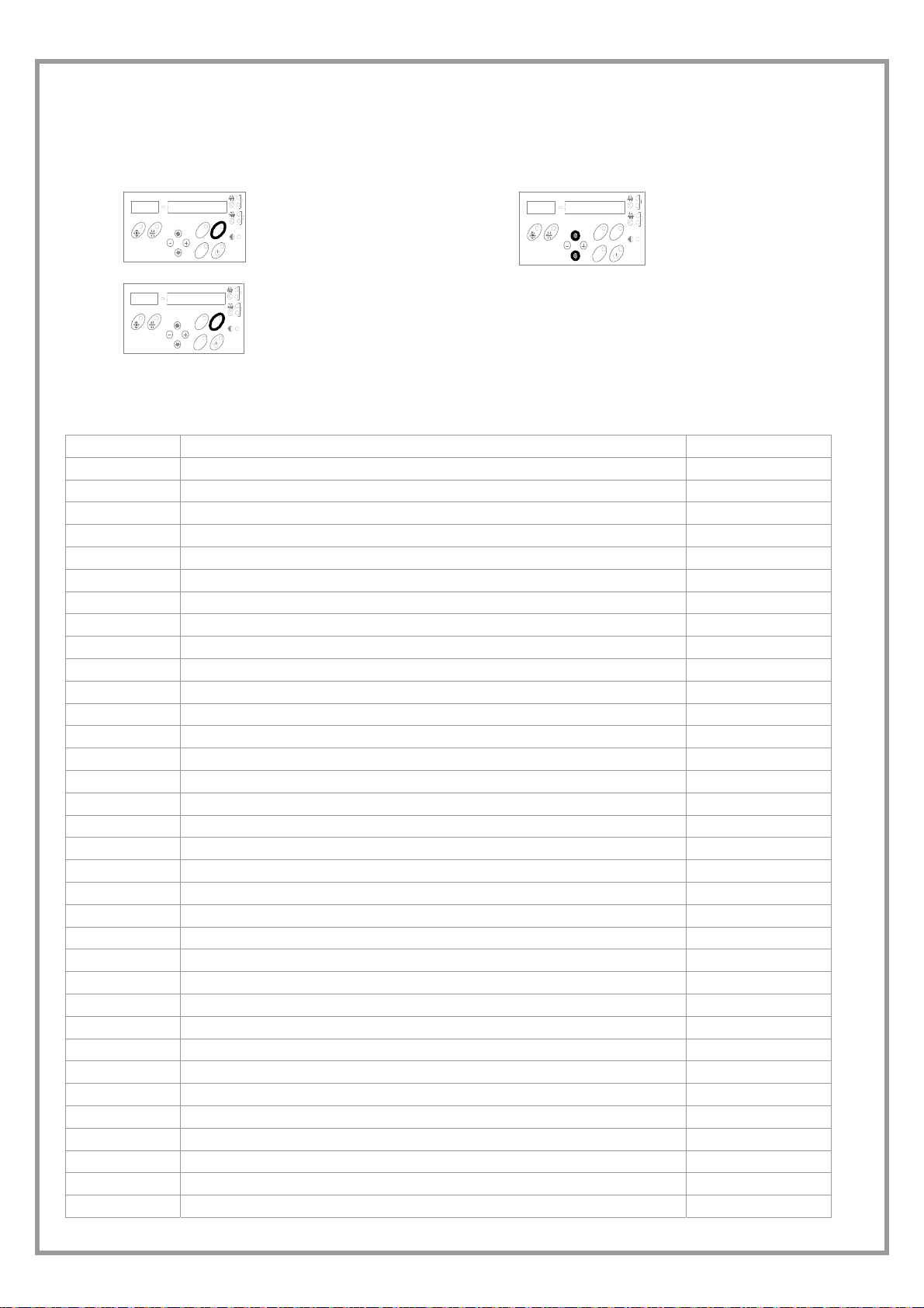
STATUS LIST
The MACHINE STATUS menu enables to display a few variables, even when an alarm is in progress.
STATUS DISPLAYING
1
3
M
AR
L
A
SET
Push STATUS button
STATUS
S
M
AR
AL
STATU
SET
STATUS to esc
2
M
AR
AL
SET
US
T
A
T
S
Select status
The tables shows all the variables which can be managed by the electronic system.
According to the machine configuration and the accessories, some alarms can be not used.
In this case, one can see “- - - “ in the display instead of the status value.
Status num. Status by keypad UM
001
002
003
004
005
006
007
008
009
010
011
012
013
014
015
016
017
018
019
020
021
022
023
024
025
026
027
028
029
030
031
032
033
034
Supply current SetPoint °C
Return current SetPoint °C
Return temperature °C
Outside temperature °C
VHeat/CoolExt control component %
VHeat/CoolAmb control component %
VHeat/CoolRec control component %
Signal of compressor inverter control %
Compressor operating mode (1= heat pump)
Active dehumidification status
Free-Cooling status
Free-Heating status
0 ÷ 1
0 ÷ 1
0 ÷ 1
0 ÷ 1
Vfan control variable %
Supply Fan control signal %
Supply Fan active Step number
0 ÷ 3
Return Fan control signal %
Return Fan active Step number
0 ÷ 3
Water coil control signal %
System water temperature °C
RH probe in Ambient %
RH probe in Supply %
External RH probe %
On-Off humidifier status
0 ÷ 1
Humidifier control signal %
Post-heating status
Preheating status (replaces the previous on/off electrostatic filter status)
0 ÷ 1
0 ÷ 1
Control signal of Electrostatic Filters %
Antifreeze probe °C
Air quality probe ppm o Volt/10
Stato serranda esterna
0 ÷ 1
Unit clock Hours
C1 operating hours Hours
C2 operating hours Hours
C1 starts Int
pag 26

035
036
037
038
039
040
041
042
043
044
045
046
047
048
049
050
C2 starts Int
Zf-t -
“keypad homologation year ” -
“keypad homologation month” -
“keypad homologation day” -
Zf-b -
“base homologation year ” -
“base homologation month” -
“base homologation day” -
Modulation time of resi stance water/control valve opening (count) sec
Correction time of resi stance water/control valve opening (count) sec
On/off status of electrostatic filters
Number of active steps of the condensing unit
Control signal of modulating preheating %
Air flow status of reduced ventilation
Status supply temperature probe °C
0 ÷ 1
0 ÷ 1
0 ÷ 1
pag 27

ROUTINE MAINTENANCE
BEFORE UNDERTAKING ANY SORT OF MAINTENANCE OR CLEANING, DISCONNECT THE ELECTRICAL POWER
SUPPLY TO THE UNIT, AND ENSURE THAT OTHER PEOPLE CANNOT RE-CONNECT IT .
All equipment is subjected to wear out.
The maintenance makes :
1. keeps the unit efficiency
2. the components last longer
3. keeps their efficiency and limits breakdowns
Therefore, it is fundamental to perform periodical checks:
a few controls can be performed by the user
(AUTONOMOUS MAINTENANCE) and they are mainly
SERVICES
Parts subject to intervention:
• EXTERNAL AIR COIL
• ROOM AIR TREATMENT COIL
• FILTERS
• STRUCTURE
• CONDENSATE DISCHARGE
EXTERNAL AIR COIL
ATTENTION: contact with the exchanger fins can cause
cuts. Wear protective gloves to perform the above
described operations.
It is extremely important that the battery gives the
maximum thermal exchange; therefore, its surface must be
cleaned from dust and deposits. Remove all impurities
from the surface.
Using an air pressure gun, clean the aluminum surface of
the battery. Be careful to direct the air in the opposite
direction of the fan air movement. Hold the gun parallel to
the fins to avoid damages. As an alternative, an aspirator
can be used to suck impurities from the air input side.
Verify that the aluminum fins are not bent or damaged. In
the event of damages, contact the authorized assistance
center and get the battery “ironed out” in order to restore
the initial condition for an optimal air flow.
AIR FILTERS
It is very important for the air treatment coil to be able to
offer maximum thermal exchange. Therefore, the unit must
always operate with the filters installed and clean.
Cleaning and replacement of filters are very important in
terms of health and hygiene.
Operation with clogged filters leads to a reduction in the air
flow rate, resulting in malfunctions and unit shutdowns. It
may even cause the unit to break down.
How often the filters need to be checked depends on the
quality of outdoor air, unit operating hours, dust and
number of persons in the rooms.
As a guideline, cleaning should ideally take place between
weekly and monthly. It is advisable to start with frequent
checks, and to adjust the frequency based on how much
dirt is discovered.
cleaning activities; otherwise, controls have to be
performed by specialized technicians (INSPECTIONS).
The machine should have a log book used to keep track of
the performed controls. This will make fixing up
breakdowns easier.
Take note of the date, type of control (autonomous
maintenance, inspection or fixing up), description of the
control, actions taken and so on.
• EXTERNAL FANS
• DUCTING
• STEAM HUMIDIFIER AND IMMERSED
ELECTRODES
• ELECTRIC ELEMENTS
ROOM AIR TREATMENT COIL
ATTENTION: accidental contact with the fins of the
exchanger may cause small cuts. When performing the
following steps, use protective gloves.
The finned surfaces of the cooling coils and especially the
condensation collection trays are the places where microorganisms and moulds most easily flourish. It is therefore
very important to clean regularly with suitable detergents
and disinfect with appropriate products as necessary.
PLEATED FILTERS
1. Remove the closing doors
2. Carefully extract the filter so that no dust reaches the
parts below
3. Wash the filtering mattress in warm water with a
common detergent.
4. Carefully rinse it under water while preventing to pour
water in the room
5. Dry the filter
6. Reinsert it to its seat
7. Reassemble the closing doors
Old filters, washing residuals and residual parts must be
disposed of, according to the law in force.
pag 28

ELECTRONIC FILTERS (OPTIONAL)
1
Materials required for maintenance:
1. Alkaline detergent A01212 (code CLIVET C6460315)
2. Acid detergent B01212 (code CLIVET C6460316)
3. Protective gloves and goggles
4. Graduated beaker
5. Manual or pneumatic pump for spraying
3
2
Pour part of the alkaline detergent into the graduated
cylinder
Dilute with one part water so as to form a 50% solution
4
Fill the spray pump with the prepared solution
5
Also spray the detergent on the base of the contacts.
Let the detergent stand for 2-3 minutes
7
Position the filter to be washed on a support so you can
work comfortably.
Spray the detergent on the blades of the electrostatic filter
6
Rinse with a jet of water or with a pressurized water cleaner
at low pressure
8
Thoroughly rinse the insulators of the electrostatic cell
Turn the filter and rinse the back as well
pag 29
After washing with alkaline detergent, this is how the filter
should look.
Otherwise repeat steps 4 to 7

9
Prepare a tub with a 1/20 solution of detergent B01212
diluted in water.
Immerge the filter you have just washed in this solution to
eliminate alkaline detergent residue.
Make sure that the solution covers the entire filter
Do not use aluminium or galvanized sheet metal tubs.
11
10
Within 2-3 minutes you will note a slight chemical reaction
with the formation of foam. This indicates that the alkaline
residues have been eliminated
12
Rinse the filter again with a jet of water or with a pressurized
water cleaner at low pressure
IONIZATION WIRES
Impurities may cause oxidation or encrustation on the
wires. These may be removed using a cloth soaked in
alcohol or with very fine grain steel wool.
Because of the high voltage that powers them, the
ionization wires are subject to wear. Yearly replacement
will prevent unexpected breakage.
If breakage occurs:
1. Remove all pieces of wire in the cell and remove the
spring that holds the wires taut.
2. Hook the spring onto the eyelet of the wire.
3. Grasp the ionization wire with a curved pincer.
4. Hook the end of the spring with the open eyelet to the
wire-tensioning rod of the electro-static cell
5. Holding the ionization wire taut with the other hand,
hook it onto the other wire-tensioning rod, again using
a curved pincer
STRUCTURE
Check the condition of the parts making up the structure.
Paint so as to eliminate or reduce oxidation at the points in the unit where this problem may occur. Check that the panelling is
fastened correctly. Poor fastening may give rise to malfunctions and abnormal noise and vibration.
CONDENSATE DISCHARGE
Dust and deposits could cause obstructions.
Clean the tank, pour some water into the tank and check water flows normally.
Dry the electrostatic cells in a warm room or in direct
sunlight for a few hours.
Keep the cells up off the ground with two pieces of wood or
metal.
pag 30

DUCTING
Check the fixing screws and the operation of the anti-vibration devices in order to prevent the transmission of vibrations in the
room.
ELECTRIC FANS
Make sure that the fans and the relative protection grids are well fixed.
Check, if possible, the unbalances of the electro-fan evident by noise and anomalous vibrations. Verify that the terminal
protection covers are closed and the cable holders are properly positioned.
STEAM HUMIDIFIER AND IMMERSED ELECTRODES
The humidifier and the cylinder contain live electrical components and hot surfaces. All maintenance operations must be
performed by qualified, experienced personnel who have been trained on possible hazards.
During operation, the steam production cylinder reaches high temperatures!
Maintenance must be performed after the cylinder has cooled. Use protective gloves.
The cylinder must be replaced periodically. This operation is necessary when lime incrustations build up on the inside such
that sufficient current passage does not occur. How frequently this needs to be done depends on the water supply. The harder
the water, the more often the cylinder will need to be replaced. The water supply must not be softened. This causes corrosion
of the electrodes, foaming and possible abnormal operation. After prolonged use or use with very hard water, the solid
deposits on the electrodes may increase in size until they adhere to the inner wall of the cylinder. With especially conductive
deposits, the plastic may heat so much that it melts, resulting in water leakage.
In case of leaks, power off the unit before touching the cylinder, because electrical current may be flowing through the water.
PERIODIC CHECKS OF CYLINDER
fortnightly after not more than 300 hours of service
quarterly after not more than 1000 hours of service
yearly
5 years
after not more than 2500 hours of service
(disposable cylinders)
after not more than 10000 hours of service (for
inspectable cylinders)
check of operation, general condition, lack of
leaks
check of operation, general condition, lack of
leaks, any replacement required
replacement of cylinder
replacement of cylinder
YEARLY CHECK OF COMPONENTS
Do not use detergents or solvents to clean plastic components.
To remove incrustations, wash with a 20% solution of vinegar or acetic acid, and then rinse with water.
filling solenoid valve
drainage solenoid valve
disconnect the electrical power supply, remove the valve, and clean
the filter
disconnect the electrical power supply, remove the bobbin,
disassemble the valve body, remove any impurities and rinse
supply tub, pipes check that they are free and without impurities
REPLACEMENT OF CYLINDER
To remove the cylinder:
• Completely drain the water.
• Cut power to the humidifier using the disconnecting switch of the unit.
• Remove the steam tube from the cylinder.
• Detach the electrical connections of the electrodes and remove the
plugs from the high-level electrodes.
• Unscrew the ring nut to remove the nozzle and the filter (when the
filter is outside the cylinder)
• Lift the cylinder to extract it
Before putting it back in place:
• The filter body does not need to be replaced. Wash it with water and
place it on the new cylinder, using the new gasket that comes with it.
• Check the gasket for the seal between the cylinder and the drain group.
1 - pipe fastening spring
2 - steam pipe
3 - filling pipe
4 - steam cylinder
5 - O-ring seal
6 - filling valve
7 - valve support
8 - discharge valve
9 - bottom tub
10 -pipe fastening spring
11 -filling pipe
12 - overflow pipe
• Put the cylinder back in place by repeating the operations in reverse order
ELECTRICAL HEATING ELEMENTS
The convector finned heating elements need to be checked regularly to ensure that they are clean and properly fastened to the
support.
pag 31

MAINTENANCE INSPECTIONS
Foresee inspection assistance carried out by authorized
centers or by qualified personnel.
The inspections should be carried out at least:
• - Every year for only the cooling units
• - Every six months for the cooling and warming
units
The frequency, however, depends on the use: in the event
of frequent use (continuous or very intermittent use, near
the operating limits, etc) or critical use (service necessary)
it is recommended to plan inspections at close intervals.
The inspections to be performed are as follows:
• verify the power supply tension (when emptied or filled)
• inspect the electrical board (status of solenoid starter
contacts, terminal closings, the status of wiring and
relevant insulations)
• inspect the absorption of the single electrical loads
• verify the cleaning and the efficiency of the exchangers
97/23 CE PED DIRECTIVE
97/23 CE PED DIRECTIVE gives instructions for installers, users and maintenance technicians as well.
Refer to local actuation norms; briefly and as an example, see the following :
• COMPULSORY VERIFICATION OF THE FIRST INSTALLATION only for units assembled on the installer’s building site
(for ex. Condensing circuit + direct expansion unit)
• CERTIFICATION OF SETTING IN SERVICE for all the units
• PERIODICAL VERIFICATIONS to be executed with the frequency indicated by the Manufacturer (see the
MAINTENANCE INSPECTIONS section)
PUT AT REST
If a long period of inactivity is foreseen, for example the
winter for the cooling unit, the following is recommended:
• to turn the power off in order to avoid electrical risks or
damages by lightning strike
• to avoid the risk of frosts as shown in the HYDRAULIC
CONNECTIONS section, and, in particular
- to empty or add glycole in the plant sections
subjected to temperatures below zero
- to empty or add glycole in the water heating coils,
also in summer
- to power antifreeze heaters if present
• inspect the cleaning of the filters (air/water)
• verify the leakage from the refrigerating circuit
• Verify the protection devices (safety valves, pressure
switches, thermostats, etc.), the adjustment systems,
the control devices (alarm signalizations, probes,
manometers, etc)
• check the operating parameters of the refrigerating
circuit (see the following REFRIGERANT TABLES and
the START-UP section)
For units equipped with safety valves, follow the
Manufacturer’s instructions.
Verify periodically the cleaning of the safety valves and
that oxidative / corrosive phenomena are not present, in
particular for installations near the sea, in industrial areas
or in rooms with a corrosive atmosphere.
If the period of inactivity is particularly long or in the event
of extremely low temperatures, the external fans can be
blocked temporarily; therefore, it is recommended to
switch them on every month in order to avoid seizures or
electrical overloads when the unit will be switched on.
The restarting of the unit has to be carried out by qualified
personnel, in particular, after the winter break for cooling
units or when seasonal switching should be performed.
When restarting, refer to the SWITCHING ON section.
Schedule technical assistance in advance to avoid hitches
and be able to use the installation when necessary.
pag 32

REFRIGERANT TABLES
THIS SECTION IS DEVOTED ONLY TO QUALIFIED TECHNICIANS THAT KNOW THE FOLLOWING:
• THE OPERATIONAL PRINCIPLES OF THE REFRIGERATING CIRCUIT OPERATION
• THE MODES OF DETECTING TEMPERATURE AND PRESSURE
• THE RISKS RELEVANT TO THESE OPERATIONS
The data of the tables allow the testing of the refrigerating circuit operation by the detection of a few objective parameters.
The data are significant if they are detected simultaneously and while the refrigerating circuit is running.
OVERHEATING
=
return temperature – Saturation temperature
condensing temperature (pressure *) – liquid temperature
SUBCOOLING
=
Return pressure 7.2 bar Condensing pressure 29.6 bar
Return temperature 7.3 °C Liquid temp. 45 °C
overheating
7.3 – 0.8 = 6.5 °C
subcooling
49.91 – 45 = 4.91 °C
* It is important that the condensation pressure is detected as close as possible to the point where the liquid temperature is
detected, in the event that the calculation will be effected by the losses of charge (and, therefore, of temperature) caused
by the refrigerating circuit components placed between the two measurement points.
Pg = P gauge = relevant pressure (read on the pressure gauge) , Ts : saturation pressure
For R410A the glide was not considered, since it is close to 0
Pg Ts [°C] Pg Ts [°C] Pg Ts [°C] Pg Ts [°C] Pg Ts [°C] Pg Ts [°C] Pg Ts [°C] Pg Ts [°C] Pg Ts [°C]
0.0 -51.66 5.0 -8.69 10.0 10.42 15.0 23.74 20.0 34.22 25.0 42.95 30.0 50.47 35.0 57.10 40.0 63.02
0.2 -48.02 5.2 -7.73 10.2 11.03 15.2 24.20 20.2 34.59 25.2 43.27 30.2 50.75 35.2 57.35 40.2 63.25
0.4 -44.83 5.4 -6.79 10.4 11.63 15.4 24.66 20.4 34.97 25.4 43.59 30.4 51.03 35.4 57.60 40.4 63.47
0.6 -41.98 5.6 -5.87 10.6 12.23 15.6 25.12 20.6 35.34 25.6 43.90 30.6 51.31 35.6 57.85 40.6 63.69
0.8 -39.40 5.8 -4.97 10.8 12.82 15.8 25.57 20.8 35.71 25.8 44.22 30.8 51.59 35.8 58.09 40.8 63.92
1.0 -37.03 6.0 -4.10 11.0 13.40 16.0 26.01 21.0 36.08 26.0 44.53 31.0 51.86 36.0 58.34 41.0 64.14
1.2 -34.84 6.2 -3.24 11.2 13.97 16.2 26.46 21.2 36.44 26.2 44.85 31.2 52.14 36.2 58.58 41.2 64.36
1.4 -32.81 6.4 -2.40 11.4 14.54 16.4 26.90 21.4 36.81 26.4 45.16 31.4 52.41 36.4 58.82 41.4 64.58
1.6 -30.90 6.6 -1.57 11.6 15.10 16.6 27.33 21.6 37.17 26.6 45.47 31.6 52.68 36.6 59.07 41.6 64.79
1.8 -29.10 6.8 -0.77 11.8 15.66 16.8 27.76 21.8 37.52 26.8 45.77 31.8 52.95 36.8 59.31 41.8 65.01
2.0 -27.39 7.0 0.02 12.0 16.20 17.0 28.19 22.0 37.88 27.0 46.08 32.0 53.22 37.0 59.55 42.0 65.22
2.2 -25.78 7.2 0.80 12.2 16.74 17.2 28.62 22.2 38.23 27.2 46.38 32.2 53.49 37.2 59.78 42.2 65.44
2.4 -24.24 7.4 1.56 12.4 17.28 17.4 29.04 22.4 38.58 27.4 46.69 32.4 53.75 37.4 60.02 42.4 65.65
2.6 -22.76 7.6 2.31 12.6 17.81 17.6 29.45 22.6 38.93 27.6 46.99 32.6 54.02 37.6 60.26 42.6 65.87
2.8 -21.35 7.8 3.05 12.8 18.33 17.8 29.87 22.8 39.28 27.8 47.28 32.8 54.28 37.8 60.50 42.8 66.08
3.0 -20.00 8.0 3.77 13.0 18.85 18.0 30.28 23.0 39.62 28.0 47.58 33.0 54.54 38.0 60.73 43.0 66.29
3.2 -18.69 8.2 4.48 13.2 19.36 18.2 30.69 23.2 39.96 28.2 47.88 33.2 54.80 38.2 60.96 43.2 66.50
3.4 -17.44 8.4 5.18 13.4 19.87 18.4 31.09 23.4 40.30 28.4 48.17 33.4 55.06 38.4 61.20 43.4 66.71
3.6 -16.22 8.6 5.87 13.6 20.37 18.6 31.49 23.6 40.64 28.6 48.46 33.6 55.32 38.6 61.43 43.6 66.92
3.8 -15.05 8.8 6.55 13.8 20.86 18.8 31.89 23.8 40.98 28.8 48.76 33.8 55.58 38.8 61.66 43.8 67.13
4.0 -13.91 9.0 7.22 14.0 21.36 19.0 32.28 24.0 41.31 29.0 49.05 34.0 55.84 39.0 61.89
4.2 -12.81 9.2 7.88 14.2 21.84 19.2 32.68 24.2 41.64 29.2 49.33 34.2 56.09 39.2 62.12
4.4 -11.74 9.4 8.53 14.4 22.32 19.4 33.07 24.4 41.97 29.4 49.62 34.4 56.34 39.4 62.35
4.6 -10.69 9.6 9.16 14.6 22.80 19.6 33.45 24.6 42.30 29.6 49.91 34.6 56.60 39.6 62.57
4.8 -9.68 9.8 9.79 14.8 23.27 19.8 33.84 24.8 42.62 29.8 50.19 34.8 56.85 39.8 62.80
pag 33

TROUBLESHOOTING
THE OPERATIONS MUST BE CARRIED OUT BY TECHNICAL QUALIFIED PERSONNEL HAVING THE REQUISITES
UNDER LAW REQUISITES AND IN CONFORMITY WITH THE SAFETY REGULATIONS IN FORCE.
THE INTERVENTIONS WITHIN THE WARRANTY PERIOD WILL BE CARRIED OUT BY AUTHORIZED SERVICE
CENTERS.
BEFORE RESETTING AN ALARM, IDENTIFY AND ELIMINATE ITS CAUSE.
REPEATED RESETS MAY CAUSE SERIOUS DAMAGES.
In certain machine configurations, some safeties may be placed in series and lead back to a single input on the electronic
module.
Therefore, check on the electrical diagram whether the device to which the alarm corresponds has other devices or
safeties connected in series.
Below is a list of the possible causes of alarms.
FAULTY PROBE
1. Identify the part on the wiring diagram.
2. Loose electric contacts/terminals, leads broken
3. Check the correct probe ohmic level (using a
tester)
4. Change the probe.
5. Check the electronic module configuration (only
an authorised service centre can do this)
6. Change the electronic module
COMPRESSOR PROTECTION
1. Identify the part on the wiring diagram
2. Loose electric contacts/terminals, leads broken
3. electrical windings interrupted
4. Vacuum power voltage below the limits
5. power contactors / contacts defective
6. start-up power voltage lower than the limits
7. electrical absorption high / unbalanced
8. High compressor discharge temperature >
thermostatic device needs calibrating, insufficient
refrigerant charge
HIGH PRESSURE
1. high air temperature (see operating limits)
2. fans do not work, direction of rotation inverted
3. insufficient air flow to coil
4. not CONSTANT flow (for example, if the pumps
are turned off, certain areas of the plant are
excluded or included, other uses are isolated,
etc)
5. dirty air filter
6. condensation gas in the cooling circuit o
7. Too much refrigerant
8. Check the trigger point for the manostat and
transducer
9. Manostat/transducer: loose electric
contacts/terminals, wiring cables interrupted
10. Check the manostat or transducer pressure
control point (deposits of oil, dirt, pin blocked
mechanically)
FAN PROTECTION
1. Identify the part on the wiring diagram
2. fan mechanically jammed, bearings / drive belt (if
present)
3. Loose electric contacts/terminals, leads broken
4. electrical windings of fan interrupted
5. power supply voltage below limits
6. electrical absorption high / unbalanced
LOW PRESSURE
1. low air temperature (see operating limits)
2. not CONSTANT flow (for example, if the pumps are
turned off, certain areas of the plant are excluded or
included, other uses are isolated, etc)
3. insufficient air flow to coil (high thermal difference
between input and output)
4. air filter dirty
5. fans do not work, direction of rotation inverted
6. Manostat/transducer: loose electric
contacts/terminals, wiring cables interrupted
7. refrigerant circuit empty, visible leaks of
refrigerant/oil, insufficient charge
8. dryer filter clogged
9. thermostatic device not operating correctly
10. Check the trigger point for the manostat and
transducer
pag 34

DECOMMISSIONING OF THE UNIT
DISCONNECTING THE UNIT
The units must be disconnected by authorised personnel,
who before proceeding must first read the Residual Risks
section in this manual.
Before disconnecting the unit, the following must be
recovered, if present:
• the refrigerant (if the circuits cannot be isolated):
the refrigerant must be removed using suction
devices operating in a closed circuit, so as to
ensure that none of the compound is released
into the atmosphere.
• the antifreeze in the circuits: when removing this
fluid, make sure that it does not leak and that it is
not released into the environment. The antifreeze
fluid must be stored in special containers.
When recovering the substances present in the unit, all
measures must be taken to avoid damaging persons and
things and polluting the surrounding area.
Awaiting dismantling and disposal, the unit can also be
stored outdoors, as bad weather and rapid changes in
temperature will not cause damage to the environment, if
electric, cooling and hydraulic circuits of the unit are
integral and closed.
DISMANTLING AND DISPOSAL
THE UNIT MUST ALWAYS BE SENT TO AUTHORISED
CENTRES FOR DISMANTLING AND DISPOSAL.
When dismantling the unit, the fan, the motor and the coil,
if operating, may be recovered by the specialist centres for
reuse.
All the materials must be recovered or disposed of in
compliance with the corresponding national standards in
force.
For further information on the decommissioning of the unit,
contact the manufacturer
.
pag 35

f V
TECHNICAL DATA
Size 17 21 25 31 41 51
COOLING
Cooling capacity 1 kW 6,2 7,6 8,6 10,9 12,4 15,9
Sensible capacity 1 kW 5 5,8 7 8,6 9,5 12,5
Compressor power input 1 kW 1,7 2,1 2,2 2,9 2,8 3,8
HEATING
Heat output 2 kW 6,8 8,3 9,2 11,9 13,2 16,9
Compressor power input 2 kW 1,3 1,7 1,8 2,2 2 2,8
COMPRESSORS
Type of compressors 3 Rot Scroll
No. of Compressors 1
Std Capacity control steps 1
Refrigerant circuits 1
AIR HANDLING SECTION FANS (OUTLET)
Type of fans 4 CFG
Number of fans 1
Standard air flow l/s] 330 390 470 610 690 920
Installed unit power kW 0,3 0,3 0,4 0,4 0,6 0,6
Max outside static pressure 5 Pa 190 175 300 180 270 340
AIR HANDLING SECTION FANS (EXHAUST)
Type of fans 4 CFG
Number of fans 1
Standard air flow l/s 300 360 440 550 640 860
Installed unit power kW 0,3 0,3 0,4 0,4 0,6 0,6
Max outside static pressure 5 Pa 180 165 290 210 250 360
DIMENSIONS
Length mm 1503
Depth mm 950
Height mm 442 517 668
(1) exhaust coil inlet air temperature 27°C B.S. - 19°C B.U.
outdoor air temperature 35°C B.S. - 24°C B.U.
(2) exhaust coil inlet air temperature 20°C B.S. - 12°C B.U.
outdoor air temperature 7°C DB - 6°C WB
(3) SCROLL = scroll compressor
ROT = rotary compressor
(4) CFG = centrifugal fan
(5) Static pressure available on unit with electronic filters (excluding integration coil)
OVERLOAD AND CONTROL DEVICE CALIBRATION
High pressure safety switch kPa 4200 3300 -Low pressure safety switch kPa 300 450 -Max no. of compressor starts per hour Nr -- -- 10
On Of
alue
pag 36

OPERATING LIMITS (COOLING)
30
25
20
15
Ta (W.B.)
10
5
5 10152025303540
(1)
To (D.B.)
OPERATING LIMITS (HEATING)
35
30
25
20
15
10
5
To (D.B.)
0
-5
-10
-15
-20
8 1012141618202224
(1)
(2)
Ta (W .B .)
SOUND LEVELS
Sound Power Level (dB)
Size
Octave band (Hz)
63 125 250 500 1000 2000 4000 8000
17
77 75 70 65 62 57 47 35 53 68
Sound
pressur
e level
dB(A)
THE LIMITS ARE INDICATIVE AND HAVE BEEN CALCULATED
CONSIDERING:
- VALUES GENERAL AND NOT SPECIFICATIONS,
- STANDARD AIR FLOW-RATE,
- NON-CRITICAL POSITIONING AND CORRECT USE OF THE
UNIT,
- OPERATION AT FULL LOAD
TA =EXTERNAL AIR TEMPERATURE/TREATMENT COIL INLET
(°C) W.B.
WB = WET BULB
TO = EXHAUST COIL INLET AIR TEMPERATURE (°C)
DB = DRY BULB
(1) THE DASHED AREA REFERS TO THE FIELD OF UNITS
OPERATION STANDARD
THE LIMITS ARE INDICATIVE AND HAVE BEEN
CALCULATED CONSIDERING:
- VALUES GENERAL AND NOT SPECIFICATIONS,
- STANDARD AIR FLOW-RATE,
- NON-CRITICAL POSITIONING AND CORRECT USE OF THE
UNIT,
- OPERATION AT FULL LOAD
TA = EXHAUST COIL INLET AIR TEMPERATURE (°C) W.B.
WB = WET BULB
TO = OUTDOOR AIR TEMPERATURE/HANDLING COIL INLET
(°C)
DB = DRY BULB
(1) THE DASHED AREA REFERS TO THE FIELD OF UNITS
OPERATION STANDARD
(2) OPERATION FIELD EXTENSION WITH PREHEATING
HEATERS
Sound
power
level
dB(A)
The sound levels are referred to units working
at full load in nominal conditions.
The sound pressure level is referred at a
distance of 1 m. From the ducted unit surface
working in free field conditions.external static
pressure 50 pa.
21
79 77 72 67 64 59 49 37 55 70
25
80 79 74 69 66 61 52 41 57 72
31
85 81 76 71 68 63 54 43 59 74
41
83 82 77 74 70 65 56 45 61 76
51
88 85 79 75 71 66 57 46 62 77
pag 37
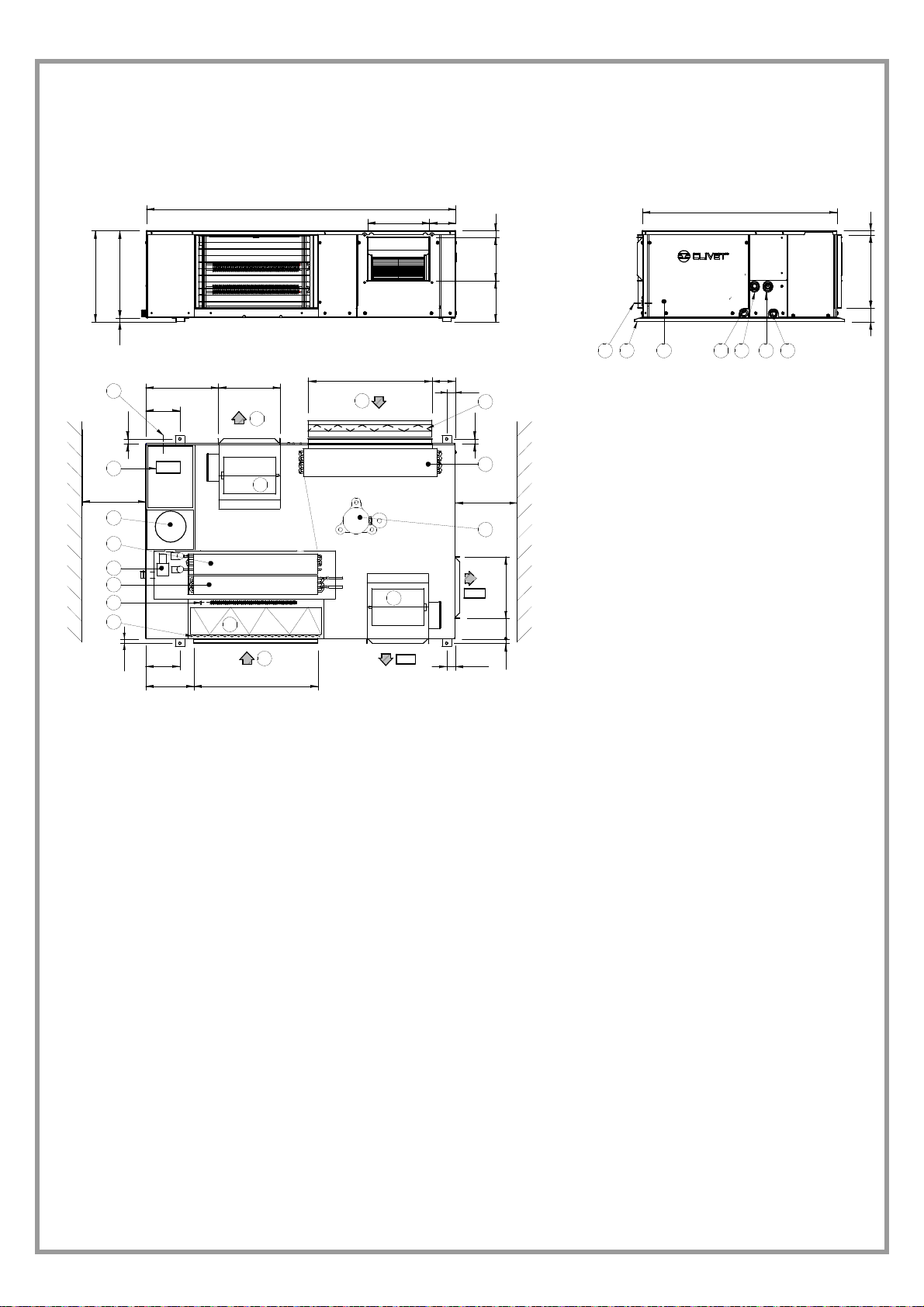
Sizes 17-21
442
18 424
13
22.5
353 301
166.5
DIMENSIONS
1503
M
R
301 128
113603
41.5
199 211 32
13
20 12
19
22.5
950
66 356 20
15 14 1716
Q.E.
2
700 min.
11
9
10
5
18
7
22.5
166.5
234 603
3
4
8
AE
ES 1
700 min.
ES 2
41.5
(1) COMPRESSOR
(2) ELECTRICAL PANEL
(3) SUPPLY FAN
(4) EXHAUST FAN
(5) TREATED AIR DIRECT EXPANSION COIL
(6) EXHAUST AIR DIRECT EXPANSION COIL
(7) AIR FILTER
(8) ELECTRIC FILTERS (OPTIONAL)
(9) ADDITIONAL WATER COIL (OPTIONAL)
(10) 3 WAYS-VALVE (OPTIONAL)
(11) STEAM HUMIDIFIER (OPTIONAL)
(12) REMOVABLE PANEL FOR ACCESS TO THE TECHNICAL
COMPARTMENT
(13) POWER INPUT
(14) WATER OUTLET ADDITIONAL COIL Ø 3/4"
(15) WATER INLET ADDITIONAL COIL Ø 3/4"
(16) HUMIDIFIER INLET WATER Ø 1/2" GAS
(17) CONDENSATE DISCHARGE
(18) AUXILIARY ELECTRIC HEATERS (OPTIONAL)
(19) EXHAUST AIR FILTER G4 (OPTIONAL)
(20) BRACKETS FOR ANCHORING THE UNIT TO THE CEILING
R = AIR INTAKE FROM OUTSIDE
M=OUTLET AIR
AE = FRESH AIR INTAKE
ES1 = STANDARD AIR EXHAUST
ES2 = OPTIONAL AIR EXHAUST
6
1
301
98.522.5
pag 38

Sizes 25-31
517
1503
230
163.5
950
261
18 499
13
22.5
2
700 min. 700 min.
11
9
10
5
18
7
388.5 230
166.5
Q.E.
165.5
22.5
234 603
R
M
3
8
AE
ES1
113603
41.5
4
ES2
41.5
(1) COMPRESSOR
(2) ELECTRICAL PANEL
(3) SUPPLY FAN
(4) EXHAUST FAN
(5) TREATED AIR DIRECT EXPANSION COIL
(6) EXHAUST AIR DIRECT EXPANSION COIL
(7) AIR FILTER
(8) ELECTRIC FILTERS (OPTIONAL)
(9) ADDITIONAL WATER COIL (OPTIONAL)
(10) 3 WAYS-VALVE (OPTIONAL)
(11) STEAM HUMIDIFIER (OPTIONAL)
(12) REMOVABLE PANEL FOR ACCESS TO THE TECHNICAL
COMPARTMENT
(13) POWER INPUT
(14) WATER OUTLET ADDITIONAL COIL Ø 3/4"
(15) WATER INLET ADDITIONAL COIL Ø 3/4"
(16) HUMIDIFIER INLET WATER Ø 1/2" GAS
(17) CONDENSATE DISCHARGE
(18) AUXILIARY ELECTRIC HEATERS (OPTIONAL)
(19) EXHAUST AIR FILTER G4 (OPTIONAL)
(20) BRACKETS FOR ANCHORING THE UNIT TO THE CEILING
R = AIR INTAKE FROM OUTSIDE
M=OUTLET AIR
AE = FRESH AIR INTAKE
ES1 = STANDARD AIR EXHAUST
ES2 = OPTIONAL AIR EXHAUST
223 261 33
20
13
19
22.5
6
1
134 230
22.5
15
12
16
14
17
66 430 21
pag 39

Size 41
1503
301
128
649
18
4
ES1
113603
700 m in
ES2
41.5
13
700 min
2
11
10
9
5
18
7
353 301
166.5
Q.E.
166.5
22.5
234 603
R
M
3
8
AE
(1) COMPRESSOR
(2) ELECTRICAL PANEL
(3) SUPPLY FAN
(4) EXHAUST FAN
(5) TREATED AIR DIRECT EXPANSION COIL
(6) EXHAUST AIR DIRECT EXPANSION COIL
(7) AIR FILTER
(8) ELECTRIC FILTERS (OPTIONAL)
(9) ADDITIONAL WATER COIL (OPTIONAL)
(10) 3 WAYS-VALVE (OPTIONAL)
(11) STEAM HUMIDIFIER (OPTIONAL)
(12) REMOVABLE PANEL FOR ACCESS TO THE TECHNICAL
COMPARTMENT
(13) POWER INPUT
(14) WATER OUTLET ADDITIONAL COIL Ø 3/4"
(15) WATER INLET ADDITIONAL COIL Ø 3/4"
(16) HUMIDIFIER INLET WATER Ø 1/2" GAS
(17) CONDENSATE DISCHARGE
(18) AUXILIARY ELECTRIC HEATERS (OPTIONAL)
(19) EXHAUST AIR FILTER G4 (OPTIONAL)
(20) BRACKETS FOR ANCHORING THE UNIT TO THE CEILING
R = AIR INTAKE FROM OUTSIDE
M=OUTLET AIR
AE = FRESH AIR INTAKE
ES1 = STANDARD AIR EXHAUST
ES2 = OPTIONAL AIR EXHAUST
265 78.5
323.5
19
22.5
6
1
301
98
22.5
265
581 20
20 12
13
15
16
17
14
66
pag 40

Size 51
13
1503
18 649
370 268
166.5
22.5
M
603
R
268 145
113
41.5
292
13
296.5 292 78.5
20
12
19
22.5
950
66 581 20
16
14
15
17
2
700 min.
11
9
10
5
18
7
Q.E.
166.5
22.5
234 603
3
4
8
AE
ES1
700 min.
ES2
41.5
(1) COMPRESSOR
(2) ELECTRICAL PANEL
(3) SUPPLY FAN
(4) EXHAUST FAN
(5) TREATED AIR DIRECT EXPANSION COIL
(6) EXHAUST AIR DIRECT EXPANSION COIL
(7) AIR FILTER
(8) ELECTRIC FILTERS (OPTIONAL)
(9) ADDITIONAL WATER COIL (OPTIONAL)
(10) 3 WAYS-VALVE (OPTIONAL)
(11) STEAM HUMIDIFIER (OPTIONAL)
(12) REMOVABLE PANEL FOR ACCESS TO THE TECHNICAL
COMPARTMENT
(13) POWER INPUT
(14) WATER OUTLET ADDITIONAL COIL Ø 3/4"
(15) WATER INLET ADDITIONAL COIL Ø 3/4"
(16) HUMIDIFIER INLET WATER Ø 1/2" GAS
(17) CONDENSATE DISCHARGE
(18) AUXILIARY ELECTRIC HEATERS (OPTIONAL)
(19) EXHAUST AIR FILTER G4 (OPTIONAL)
(20) BRACKETS FOR ANCHORING THE UNIT TO THE CEILING
R = AIR INTAKE FROM OUTSIDE
M=OUTLET AIR
AE = FRESH AIR INTAKE
ES1 = STANDARD AIR EXHAUST
ES2 = OPTIONAL AIR EXHAUST
6
1
115 268
22.5
pag 41

pag 42

pag 43

PROHIBIDA la reproducción total o parcial - Copyright-CLIVET S.p.a.-Feltre (BL)- Italia
CLIVET SPA
Via Camp Lonc 25, Z.I. Villapaiera - 32032 Feltre (BL) - Italy
Tel. + 39 0439 3131 - Fax + 39 0439 313300 - info@clivet.it
CLIVET UK LTD
4 Kingdom Close, Segensworth East - Fareham, Hampshire - PO15 5TJ - United Kingdom
Tel. + 44 (0) 1489 572238 - Fax + 44 (0) 1489 573033 - info@clivet-uk.co.uk
CLIVET AIRCON LTD (Service and Maintenance Division)
Units F5&F6 Railway Triangle Ind Est, Walton Road - Portsmouth, Hampshire - PO6 1TG - United Kingdom
Tel. + 44 (0) 2392 381235 - Fax + 44 (0) 2392 381243 - info@clivetaircon.co.uk
CLIVET ESPAÑA COMERCIAL S.L. (Sales)
Calle Gurb, 17 1° 1a - 08500 Vic, Barcelona - España
Tel. + 34 93 8606248 - Fax + 34 93 8855392 - info@clivetcomercial.com
CLIVET ESPAÑA S.A.U.(Service and Maintenance Division)
Calle Real de Burgos N° 12 - 28860, Paracuellos del Jarama, Madrid - España
Tel. + 34 91 6658280 - Fax + 34 91 6657806 - info@clivet.es
CLIVET GmbH
Hummelsbütteler Steindamm 84, 22851 Norderstedt - Germany
Tel. + 49 (0) 40 32 59 57-0 - Fax + 49 (0) 40 32 59 57-194 - info.de@clivet.com
CLIVET NEDERLAND B.V.
Siliciumweg 20a, 3812 SX Amersfoort - Netherlands
Tel. + 31 (0) 33 7503420 - Fax + 31 (0) 33 7503424 - info@clivet.nl
CLIVET RUSSIA
Elektrozavodskaya st. 24, office 509 - 107023, Moscow, Russia
Tel. + 74956462009 - Fax + 74956462009 - info.ru@clivet.com
CLIVET MIDEAST FZCO
Dubai Silicon Oasis (DSO), High Bay Complex, Ind Unit No. 3, PO BOX 28178 - Dubai, UAE
Tel. + 9714 3208499 - Fax + 9714 3208216 - info@clivet.ae
CLIVET AIRCONDITIONING SYSTEMS PRIVATE LIMITED
4BA, Gundecha Onclave - Kherani Road, Saki Naka, Andheri (East) - Mumbai 400 072 - India
Tel. + 91 22 6193 7000 - Fax + 91 22 6193 7001 - info.in@clivet.com
Los datos y las imágenes contenidos en este manual pueden ser cambiados o modificados sin previo aviso.
www.clivet.com
 Loading...