


M06K40A18-00
CKN-XHE2i 7.1-14.2
High eciency “Roof Top” air cooled heat pump
Installation and
operating manual
08-05-18

Dear Customer,
We congratulate you on choosing this product
For many years Clivet has been oering systems that provide maximum comfort, together with high
reliability, eciency, quality and safety.
The aim of the company is to oer advanced systems, that assure the best comfort, reduce energy
consumption and the installation and maintenance cost for the life cycle of the system.
The purpose of this manual is to provide you with information that is useful from reception of
the equipment, through installation, operational usage and nally disposal so that this advanced
system oers the beat solution.
Yours faithfully.
CLIVET Spa
The data contained in this manual is not binding and may be changed by the manufacturer without
prior notice.
Reproduction, even is part, is FORBIDDEN © Copyright - CLIVET S.p.A. - Feltre (BL) - Italia

Index of contents
1 General description
2 Reception
3 Positioning
4 Water connections
5 Aeraulic connections
6 Electrical connections
7 Start-up
8 Control
9 Maintenance
10 Accessories
11 Decommissioning
12 Residual risks
13 Technical information
4
6
9
13
14
15
20
26
4
5
54
5
M06K40A18-00 CKN-XHE2i 7.1-14.2 3

1 General description
1.1 Manual
The manual provides correct unit installation, use and maintenance.
Pay particular attention to:
Warning, identies particularly important operations or information.
Prohibited operations that must not be carried out, that compromise the operating of the unit or may cause damage to persons or things.
It is advisable to read it carefully so you will save time during operations.
•
Follow the written indications so you will not cause damages to things and injuries people.
•
1.2 Preliminaries
Only qualied personnel can operate on the unit, as required by the regulation in force.
1.3 Risk situations
The unit has been designed and created to prevent injures to people.
During designing it is not possible to plane and operate on all risk situation.
Read carefully “Residual risk” section where all situation which may cause damages to things and injuries to people are reported.
Installation, starting, maintenance and repair required specic knowledge; if they are carried out by inexperienced personnel, they may cause
damages to things and injuries people.
1.4 Intended use
Use the unit only:
civil air-conditioning
•
keep to the limits foreseen in the technical schedule and in this manual
•
The manufacturer accepts no responsibility if the equipment is used for any purpose other than the intended use.
1.5 Installation
Outdoor installation
The positioning, hydraulic system, refrigerating, electrics and the ducting of the air must be determined by the system designer in accordance
with local regulations in force.
Follow local safety regulations.
Verify that the electrical line characteristics are in compliance with data quotes on the unit serial number label.
1.6 Maintenance
Plan periodic inspection and maintenance in order to avoid or reduce repairing costs.
Turn the unit o before any operation.
1.7 Modication
All unit modications will end the warranty coverage and the manufacturer responsibility.
1.8 Breakdown/Malfuction
Disable the unit immediately in case of breakdown or malfunction.
Contact a certied service agent.
Use original spares parts only.
Using the unit in case of breakdown or malfunction:
voids the warranty
•
it may compromise the safety of the unit
•
may increase time and repair costs
•
4 CKN-XHE2i 7.1-14.2 M06K40A18-00

1.9 User training
The installer has to train the user on:
Start-up/shutdown
•
Set points change
•
Standby mode
•
Maintenance
•
What to do / what not to do in case of breakdown
•
1.10 Data update
Continual product improvements may imply manual data changes.
Visit manufacturer web site for updated data.
1.11 Indications for the User
Keep this manual with the wiring diagram in an accessible place for the operator.
Note the unit data label so you can provide them to the assistance centre in case of intervention (see “Unit identication” section).
Provide a unit notebook that allows any interventions carried out on the unit to be noted and tracked making it easier to suitably note the
various interventions and aids the search for any breakdowns.
In case of breakdown or malfunction:
Immediately deactivate the unit
•
Contact a service centre authorized by the manufacturer
•
The installer must train the user, particularly on:
Start-up/shutdown
•
Set points change
•
Standby mode
•
Maintenance
•
What to do / what not to do in case of breakdown
•
1.12 Unit indentication
The serial number label is positioned on the unit and allows to indentify all the unit features.
The matriculation plate shows the indications foreseen by the standards, in particular:
unit type
•
serial number (12 characters)
•
year of manufacture
•
wiring diagram number
•
electrical data
•
type of refrigerant
•
refrigerant charge
•
manufacturer logo and address
•
The matriculation plate must never be removed.
It contains uorinated greenhouse gases
Type of refrigerant: R410A
1.13 Serial number
It identies uniquely each unit.
Must be quoted when ordering spare parts.
1.14 Assistance request
Note data from the serial number label and write them in the chart on side, so you will nd them easily when needed.
Series
Size
Serial number
Year of manufacture
Electrical wiringdiagram
M06K40A18-00 CKN-XHE2i 7.1-14.2 5

2 Reception
You have to check before accepting the delivery:
That the unit hasn’t been damaged during transport
•
That the materials delivered correspond with that indicated on the transport document comparing the data with the identication label
•
positioned on the packaging.
In case of damage or anomaly:
Write down on the transport document the damage you found and quote this sentence: “Conditional acceptance clear evidence of
•
deciencies/damages during transport”
Contact by fax and registered mail with advice of receipt to supplier and the carrier.
•
Any disputes must be made within 8 days from the date of the delivery. Complaints after this period are invalid.
2.1 Storage
Observe external packaging instructions.
2.2 Handling
1. Verify unit weight and handling equipment lifting capacity.
2. Identify critical points during handling (disconnected routes, ights, steps, doors).
3. Suitably protect the unit to prevent damage.
4. lifting brackets
5. Lifting with balance
6. Lifting with spacer bar
7. Align the barycenter to the lifting point
8. Use all the lifting brackets (see the dimensional section)
9. Gradually bring the lifting belts under tension, making sure they are positioned correctly.
10. Before starting the handling, make sure that the unit is stable.
6 CKN-XHE2i 7.1-14.2 M06K40A18-00

M06K40A18-00 CKN-XHE2i 7.1-14.2 7

2.3 Packaging removing
Be careful not to damage the unit.
Keep packing material out of children’s reach it may be dangerous.
Recycle and dispose of the packaging material in conformity with local regulations.
8 CKN-XHE2i 7.1-14.2 M06K40A18-00

3 Positioning
During positioning consider these elements:
Technical spaces requested by the unit
•
Electrical connections
•
Water connections
•
Spaces for air exhaust and intake
•
3.1 Functional spaces
Functional spaces are designed to:
guarantee good unit operation
•
carry out maintenance operations
•
protect authorized operators and exposed people
•
Respect all functional spaces indicated in the DIMENSIONS section.
Double all functional spaces if two or more unit are aligned.
3.2 Positioning
Units are designed to be installed:
EXTERNAL
•
in xed positions
•
Limit vibration transmission:
use anti-vibration devices or neoprene strips on the unit support points
•
install exible joints on the hydraulic connections
•
install exible joints on the hydraulic connections
•
Choose the installation place according to the following criteria:
Customer approval
•
safe accessible position
•
technical spaces requested by the unit
•
spaces for the air intake/exhaust
•
max. distance allowed by the electrical connections
•
install the unit raised from the ground
•
verify unit weight and bearing point capacity
•
verify that all bearing points are aligned and leveled
•
condensate water draining
•
consider the maximum possible snow level
•
Avoid installations in places subject to ooding
•
Protect the unit with suitable fence in order to avoid access to unauthorised personnel (children, vandals, etc.)
A correct circulation of the air is mandatory to guarantee the good unit operating.
Avoid therefore:
obstacles to the airow
•
diculty of air exchange
•
leaves or other foreign bodies that can obstruct the air coil
•
winds that hinder or favour the airow
•
heat or pollution sources close to the unit (chimneys, extractors etc..)
•
stratication (cold air that stagnates at the bottom)
•
recirculation (expelled air that is sucked in again)
•
incorrect positioning, close to very high walls, attics or in angles that could give rise to stratication or recirculation phenomenons
•
Ignoring the previous indications could:
reduce energy eciency
•
alarm lockout due to HIGH PRESSURE (in summer) or LOW PRESSURE (in winter)
•
M06K40A18-00 CKN-XHE2i 7.1-14.2 9

1
5
2
3
4
1 Positioning on concrete oor 5 Positioning on steel structure
2 2 cm thick neoprene strips 6 antivibration mounts
3 concrete oor 7 steel structure
4 insulation 8 steel structure
Avoid the accumulation of snow and ice in front of the exhaust air outlet
6
7
8
3.3 Saftey valve gas side
The installer is responsible for evaluating the opportunity of installing drain tubes, in conformity with the local regulations in force (EN 378).
3.4 Condensate water
When a heat pump is running it produces a considerable amount of water due to the defrosting cycles of the external coil.
The condensate must be disposed in order to avoid damages to people and things.
10 CKN-XHE2i 7.1-14.2 M06K40A18-00

3.5 Congurations CBK, CCK
CUFFIA ARIA ESTERNA - EXTERNAL AIR HOOD
1 - APRIRE CUFFIA ARIA ESTERNA – All’interno ci sono le finiture DX e SX, rete AE + viti di fissaggio
1 – OPEN THE EXTERNAL AIR HOOD – Inside there are right and left parts, grid EA + fixing screws
Togliere viti e
staffa di fissaggio
Remove screws
and
mounting bracket
2 - FISSARE LE FINITURE DX E SX - Esternamente e internamente, sugli appositi fori con le viti in dotazione.
2 – FIX RIGHT and LEFT PARTS - With screws supplied, on the appropriate holes internal and external side.
FISSAGGI ESTERNI - EXTERNAL FIXING FISSAGGI INTERNI - INTERNAL FIXING
Le pieghe in basso devono andare verso l’esterno della cuffia !
The folds on the bottom must be installed on the external side of the air hood !
M06K40A18-00 CKN-XHE2i 7.1-14.2 11

3 - FISSARE LA RETE ARIA ESTERNA ( AE )- Sugli appositi fori con le viti in dotazione.
3 – FIX GRID EXTERNAL AIR ( EA )- With screws supplied, on the appropriate holes.
La piega deve andare verso l’esterno della cuffia
The fold must be installed on the external side of the air hood
3.6 Electronic lter
For details see:
10.1 Electronic ltersp.47
3.7 Gas module
For details see:
10.4 Modulating condensation gas heating modulep.51
12 CKN-XHE2i 7.1-14.2 M06K40A18-00

4 Water connections
4.1 Condensate drain
The condensate must be disposed in order to avoid damages to people and things.
Unit discharge tting: the connection must not transmit mechanical stresses and must be performed taking care not to damage the unit
•
discharge tting.
Provide a siphon that, eliminating the negative pressure caused by the fan, prevents the air intake from the discharge duct.
•
The ducting must have a min. slope of 3% to allow the runo.
•
Anchor the ducting with an adequate number of supports.
•
Insulate the duct and the siphon to avoid the condensate drippings.
•
Connect the condensate discharge to a sewerage drainage network.
•
DO NOT use white water or drainage networks to avoid the aspiration of odours in the case of evaporation of water contained in the siphon.
Check at the end of the work, the regular condensate runo pouring some water in the tray.
4.2 Risk of freezing
If the unit or the relative water connections are subject to temperatures close to 0°C:
mix water with glycol, or
•
safeguard the pipes with heating cables placed under the insulation, or
•
empty the system in cases of long non-use
•
4.3 Anti-freeze solution
The use of an anti-freeze solution results in an increase in pressure drop.
Make sure that the glycol type utilized is inhibited (not corrosive) and compatible with the water circuit components.
Do not use dierent glicol mixture (i.e. ethylene with propylene).
4.4 Humidier
For details see:
10.3 Immersed electrode humidierp.49
M06K40A18-00 CKN-XHE2i 7.1-14.2 13

5 Aeraulic connections
The dimensioning and correct execution of the aeraulic connections are fundamental to guarantee good unit operation and adequate level
of silence in the room.
When designing and manufacturing the ducting, consider LOAD LOSSES, AIR FLOW AND SPEED that must be consistent with the unit features.
Particularly consider that load losses higher than the unit useful prevalence, lead to reduction in ow rate, with consequent unit blocks.
the weight of the channels must not burden on the connection anges
•
place anti-vibration joints between channels and unit
•
connection to the anges and between the various sections of the channels must guarantee air seal, avoiding dispersions penalising the
•
overall eciency of the system
limit the load losses by optimising the path, the type and number of bends and junctions
•
use wide bends evaluating the opportunity of equipping them with deectors (in particular with high air speed or bends with reduced
•
radius)
5.1 Treated air channelling
The internal surface of the channel must be smooth, enable its washing and must not contaminate the air.
Thermally isolate the channels and the anges to avoid energy losses and forming of condensation.
DIFFUSERS INLETS GRILLES
A correct diusion of the air in the room is determining for the level of comfort.
When choosing and positioning the grilles, inlets and diusers, avoid:
excessive air speed
•
forming of stagnant and stratication areas
•
cold air delivery in room
•
forming of localised currents (also due to uneven distribution of air)
•
excessive room temperature variations, vertically and horizontally
•
short circuits of the supply air towards the return air
•
For sound comfort, consider that:
the air diusers must be chosen verifying the sound power generated at nominal ow rate conditions
•
the cut-o to diusers must be carried out with exible elements
•
the return grilles must be widely dimensioned
•
Thermally isolate the channels and the anges to avoid energy losses and forming of condensation.
14 CKN-XHE2i 7.1-14.2 M06K40A18-00

6 Electrical connections
The characteristics of the electrical lines must be determined by qualied electrica personnel able to design electrical installations; moreover,
the lines must be in conformity with regulations in force.
The protection devices of the unit power line must be able to stop all short circuit current, the value must be determined in accordance with
system features.
The power cables and the protection cable section must be dened in accordance with the characteristics of the protections adopted.
All electrical operations should be performed by trained personnel having the necessary qualications required by the regulations in force
and being informed about the risks relevant to these activities.
Operate in compliance with safety regulations in force.
6.1 Electrical data
The serial number label reports the unit specic electrical data, included any electrical accessories.
The electrical data indicated in the technical bulletin and in the manual refer to the standard unit, accessories excluded.
The matriculation plate shows the indications foreseen by the standards, in particular:
Voltage
•
F.L.A.: full load ampere, absorbed current at maximum admitted conditions
•
F.L.I.: full load input, full load power input at max. admissible condition
•
Electrical wiringdiagram Nr.
•
6.2 Connections
1. Refer to the unit electrical diagram (the number of the diagram is shown on the serial number label).
2. Verify that the electrical supply has characteristics conforming to the data shown on the serial number label.
3. Before starting work, ensure the unit is isolated, unable to be turned on and a safety sign used.
4. Ensure correct earth connection.
5. Ensure cables are suitably protected.
6. Respect the indicated phase sequence
7. Before powering up the unit, make sure that all the protections that were removed during the electrical connection work have been
restored.
6.3 Signals / data lines
Do not exceed the maximum power allowed, which varies, according to the type of signal.
Lay the cables far from power cables or cables having a dierent tension and that are able to emit electromagnetic disturbances.
Do not lay the cable near devices which can generate electromagnetic interferences.
Do not lay the cables parallel to other cables, cable crossings are possible, only if laid at 90°.
Connect the screen to the ground, only if there aren’t disturbances.
Guarantee the continuity of the screen during the entire extension of the cable.
Respect impendency, capacity and attenuation indications.
6.4 Power input
Fix the cables: if vacated may be subject to tearing.
The cable must not touch the compressor and the refrigerant piping (they reach high temparatures).
M06K40A18-00 CKN-XHE2i 7.1-14.2 15

6.5 Connections performer by customer
16 CKN-XHE2i 7.1-14.2 M06K40A18-00

6.6 Remote ON-OFF
Do not perform short On O cycles
Do not use the remote On O with thermoregulation function.
YES NO !
A B
B
A B
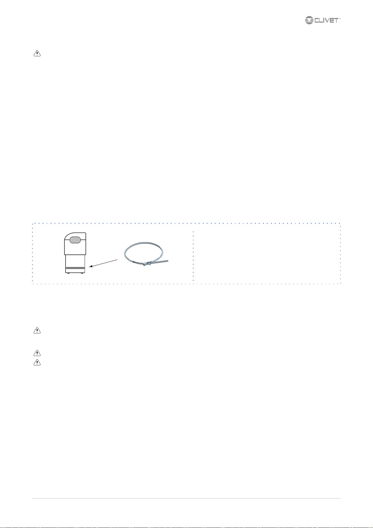
6.7 Wall mounted electronic room control
Before proceeding, make sure you have:
Name Quantity Notes
Controller 1 KJRH-120H/BMKO-E
Half-round Phillips head mounting screw 3 GB950-86 M4X20 For mounting on wall
Half-round Phillips head mounting screw 2 M4X25 GB823-88 For mounting on electrical junction box
Plastic bolt 2 To install the controller inside the switch box
Plastic expansion plug 3 For mounting on wall
Do not install in a place subject to ammable gas leaks. Once the ammable gases have leaked and spread around the controller, they could
trigger a re.
Do not place the controller near lamps, in order to prevent potential interferences with the controller signal
Do not install the unit in a place subject to excessive amounts of oil, vapour, sulphide gases. Exposure to these substances may cause the
product to deform and stop working.
The wiring must be suited to the controller’s current rating. If not, electrical dispersions or overheating may occur, which could trigger a re.
The controller operates with a low-voltage circuit. Never connect it to a standard 220 V/380 V circuit or insert it through the same cable
grommet of the circuit.
The shielded cable must be stably grounded, or the transmission might fail.
After making the connections, do not use the insulation tester to check the signal cable’s insulation.
Do not apply any external force on the terminal. This may cause the wires to break or overheating, which could trigger a re.
A
B
M06K40A18-00 CKN-XHE2i 7.1-14.2 17

Take a slotted-head screwdriver and insert it into the recess on the lower part of the controller, then turn the screwdriver to lower the back
cover. (Pay attention to the rotation direction, or the back cover may get damaged!)
Use three GB950-86 M4X20 screws to install the back cover directly onto the wall.
Use two GB823-88 M4X25 screws to install the back cover in the electrical junction box 86 and use one GB950-86 M4X20 screw to install it
directly onto the wall.
Adjust the length of the two plastic plugs to the standard distance from the threaded bar of the wall-mounted switch box. When inserting the
plastic plugs into the wall, make sure that the lie ush with the wall.
Use Phillips-head screws to fasten the back cover of the controller to the wall using the plastic plug. Make sure that the back cover of the
controller lies at the same level after installation and mount the controller back onto the rear cover.
Install the back cover correctly and securely fasten both the front and back covers, otherwise the front cover could fall.
18 CKN-XHE2i 7.1-14.2 M06K40A18-00

Make sure that no water penetrates inside the controller; use mastic and other contraptions to seal the cable connectors during installation.
Adjust the front cover then fasten it; avoid blocking the cables during installation.
The sensor must not be subject to humidity.
M06K40A18-00 CKN-XHE2i 7.1-14.2 19

7 Start-up
7.1 General description
The indicated operations should be done by qualied technician with specic training on the product.
Upon request, the service centres performing the start-up.
The electrical, water connections and the other system works are by the installer.
Agree upon in advance the star-up data with the service centre.
Before checking, please verify the following:
the unit should be installed properly and in conformity with this manual
•
the electrical power supply line should be isolated at the beginning
•
the unit isolator is open, locked and equipped with the suitable warning
•
make sure no tension is present
•
After turning o the power, wait at least 5 minutes before accessing to the electrical panel or any other electrical component.
Before accessing check with a multimeter that there are no residual stresses.
7.2 Preliminary checks
For details refer to the dierent manual sections.
Unit OFF power supply
1. safety access
2. functional spaces
3. air ow: correct return and supply (no bypass, no stratication)
4. structure integrity
5. fans run freely
6. unit on vibration isolators
7. air lters present and clean
8. completed aeraulic system
9. refrigerant circuit visual check
10. earthing connection
11. power supply features
12. electrical connections provided by the customer
7.3 Start-up sequence
For details refer to the dierent manual sections.
Unit ON power supply
1. the compressor crankcase heating elements have been running for at least 12 hours
2. o-load voltage measure
3. phase sequence check
4. shut-o valve refrigerant circuit open
5. unit ON
6. load voltage measure and absorptions
7. check all fan operating
8. check air ow on outer coil (no by-pass, no stratication)
9. air ow rate measurement
10. supply, return and outdoor air temperature measurement
11. measure super-heating and sub-cooling
12. check no anomalous vibrations are present
13. climatic curve personalization
14. climatic curve personalization
15. scheduling personalization
16. re alarm conguration *
17. complete and available unit documentation
* only if present
20 CKN-XHE2i 7.1-14.2 M06K40A18-00

7.4 Refrigeration circuit
1. Check carefully the refrigerating circuit: the presence of oil stains can mean leakage caused by transportation, movements or other).
2. Verify that the refrigerating circuit is in pressure: Using the unit manometers, if present, or service manometers.
3. Make sure that all the service outlets are closed with proper caps; if caps are not present a leak of refrigerant can be possible.
4. Open the valves of the refrigerant circuit, if there are any.
7.5 Water circuit
1. Before realizing the unit connection make sure that the hydraulic system has been cleaned up and the cleaning water has been drained.
2. Check that the water circuit has been lled and pressurized.
3. Check that the shut-o valves in the circuit are in the “OPEN” position.
4. Check that there isn’t air in the circuit, if required, evacuate it using the air bleed valve placed in the system high points.
5. When using antifreeze solutions, make sure the glycol percentage is suitable for the type of use envisaged.
Neglecting the washing will lead to several lter cleaning interventions and at worst cases can cause damages to the exchangers and the
other parts.
Weight of glycol (%) 10 20 30 40
Freezing temperature (°C) -3.9 -8.9 -15.6 -23.4
Safety temperature (°C) -1 -4 -10 -19
7.6 Electric Circuit
Verify that the unit is connected to the ground plant.
Check the conductors are tightened as: the vibrations caused by handling and transport might cause these to come loose.
Connect the unit by closing the sectioning device, but leave it on OFF.
Check the voltage and line frequency values which must be within the limits: 400/3/50 +/- 10%
Check and adjust the phase balance as necessary: it must be lower than 2%
Example
Working outside of these limits can cause irreversible damages and voids the warranty.
7.7 Compressor crankcase heaters
Power the heating elements of the compressor oil for at least 12 hours before the compressor starts:
at the rst unit start-up
•
after each prolonged period of inactivity
•
1. Supply the resistances switching o the unit isolator switch.
2. The heating elements activate with an outdoor temperature below 3°C.
3. To make sure that heaters are working, check the power input.
4. At start-up the compressor crank-case temperature on the lower side must be higher at least of 10°C than the outside temperature.
Do not start the compressor with the crankcase oil below operating temperature.
M06K40A18-00 CKN-XHE2i 7.1-14.2 21

7.8 Voltages
Check that the air and water temperatures are within in the operating limits.
Start-up the unit.
With unit operating in stable conditions, check:
Voltage
•
Total absorption of the unit
•
Absorption of the single electric loads
•
7.9 Remote controls
Check that the remote controls (ON-OFF etc) are connected and, if necessary, enabled with the respective parameters as indicated in the
“electrical connections” section.
Check that probes and optional components are connected and enabled with the respective parameters (“electrical connections” section and
following pages).
7.10 Air ow management
Standard mode
The delivery air ow stays constant as the thermal load varies.
The ventilation remains active even when the setpoint is fullled.
Constant air ow rate
Option
The delivery air ow rate stays constant during variations in the thermal load and head losses of the unit and system.
The ventilation remains active even when the setpoint is fullled.
Variable airow
Option
The air ow supply varies depending on the heat load, up to a minimum value compatible with the distribution system and the chosen air
diusion.
The ventilation remains active even when the setpoint is fullled.
7.11 Air ow setting
Standard mode
The real unit ow is according to the aeraulic system features.
Before checking, make sure that the system has been completed in all its parts (shunts, dampers, grilles, diusers etc.).
Check the doors and windows of the serviced room are closed.
The unit must be calibrated while full recirculation has been running for at least 30 minutes.
The unit is in full recirculation during the rst 60 minutes of operation.
Set the fan’s percentage of operation:
FanSpeedOutMand
22 CKN-XHE2i 7.1-14.2 M06K40A18-00

7.12 ECO mode
The air
ow supply remains constant at varied heat loads and is shutdown when setpoint is fullled.
To further increase the energy savings in this condition, it is also possible to set less demanding operation setpoints for the unit in respect to
the standard mode.
This function is indicated for the thermal maintenance of the served area in case it is temporarily not used, which can for example occur
at night.
In ECO mode, the renewal air is not managed.
The ECO mode can be activated:
Manually: P04 Enable EcoMode = 1
•
Automatically by means supervision system
•
Example in cooling mode:
7.13 Operating mode
The set point can be xed (1) or variable depending on the outdoor temperature (2).
Menu: Auto Temp. Setting
The HEAT/COOL mode can be modied:
manually through the SA5 contact, from the keypad or through the BMS
•
automatically depending on the return temperature
•
To choose, set 1.06 EnMode.
Entonces será posible elegir entre 4 tipos de funcionamiento:
1. Fixed set point - Manual mode
2. Fixed set point - Automatic mode
3. Variable set point - Manual mode
4. Automatic set point - Automatic mode
M06K40A18-00 CKN-XHE2i 7.1-14.2 23

Fixed set point - Manual mode
Fixed set point - Automatic mode
Variable set point - Manual mode
Automatic set point - Automatic mode
24 CKN-XHE2i 7.1-14.2 M06K40A18-00

7.14 Fire alarm: conguration
It is possible to congure the unit behaviour in presence of alarm signal.
Par 1.11 TypeFireMode
The unit cannot be used as smoke extractor.
Any re detection devices built-in the unit must be considered as an auxiliary safety system, and, accordingly, must not be a replacement for
any re detection devices in the room.
7.15 Room pressure calibration
CCK congurations
1. check the doors and windows of the serviced room are closed
2. calibration must be carried out with unit all in recirculation
3. view the status on the display: Pf2 RETURN AIR PRE
4. wait for the pressure value to stabilise and take note of the value
5. to keep the room at neutral pressure, memorise the value of the read pressure in 5.07 SetPAmb
6. to maintain the room in overpressure, memorise a higher value respect to that detected
7. to maintain the room in depression, memorise a lower value
7.16 Start-up report
Identifying the operating objective conditions is useful to control the unit over time.
With unit at steady state, i.e. in stable and close-to-work conditions, identify the following data:
total voltages and absorptions with unit at full load
•
absorptions of the dierent electric loads (compressors, fans, pumps etc)
•
temperatures and ows of the dierent uids (water, air) both in input and in output from the unit
•
temperature and pressures on the characteristic points of the refrigerating circuit (compressor discharge, liquid, intake)
•
The measurements must be kept and made available during maintenance interventions.
7.17 2014/68/UE PED directive
DIRECTIVE 2014/68/UE PED gives instructions for installers, users and maintenance technicians as well.
Refer to local regulations; briey and as an example, see the following:
Compulsory verication of the rst installation:
only for units assembled on the installer’s building site (for ex. Condensing circuit + direct expansion unit)
•
Certication of setting in service:
for all the units
•
Periodical verications:
to be executed with the frequency indicated by the Manufacturer (see the “maintenance inspections” paragraph)
•
M06K40A18-00 CKN-XHE2i 7.1-14.2 25

MENU
26
To access the various menus of the HOME page.
▲ up, ▼ down, ◄ left, ► right
▲, ▼, ◄ ►
OK
ON/OFF
BACK
UNLOCK
To shift the cursor, modify the selection or modify the set value.
The parameter can be rapidly modified by pressing it extendedly..
To confirm an operation
To set the ON / OFF function
To return to the previous level.
Press to exit the current page and return to the previous page.
Press extendedly to return to the home page directly.
To lock/unlock.
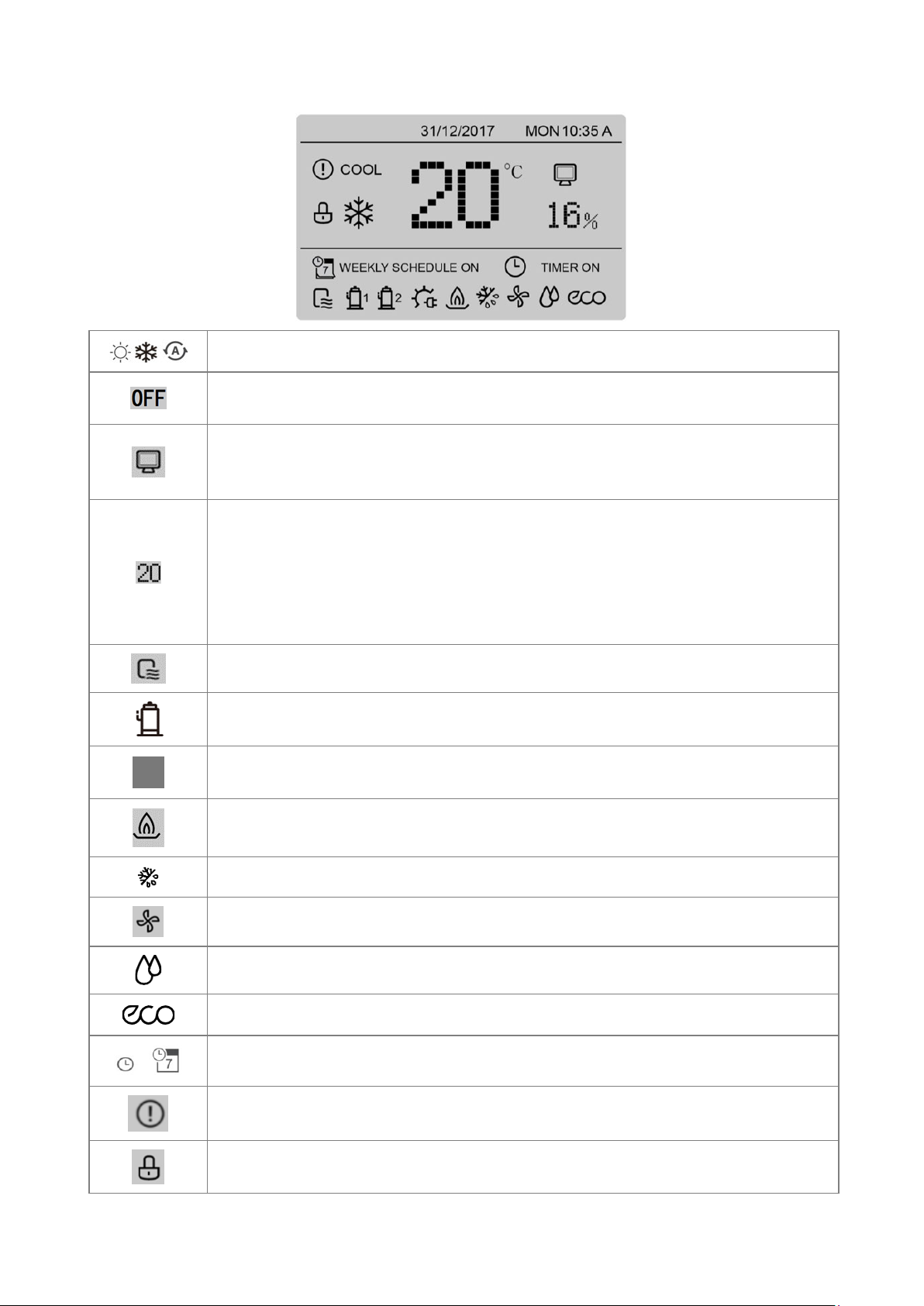
Mode: indicates, respectively, heat, cool and auto
27
Controller deactivated (off)
Remotely controlled controller
Appears when the unit is set from the keypad for being controlled from a remote terminal
or a remote switch.
Return air temperature.
16: value of the return air humidity (indicator on only when humidity check is enabled)
Generally, this area displays the actual temperature of the return air and the relative
humidity of the return air; when the set value is modified, it displays the modified
temperature and the relative humidity.
Unit status: indicator on when the unit is running.
Compressor: indicator on when the compressor is running.
Auxiliary electric heater: indicator on when the auxiliary electric heater
or H2O coil is running.
Gas module: indicator on when the gas module is running.
Defrosting: indicator on when the unit is defrosting the outdoor coil
Internal fan: indicator on when the internal fan is running.
Humidifier: indicator on when the humidifier is running.
Eco running: indicator on when the ECO function is set to ON
Timer: indicator on when a valid timer has been set (weekly schedule).
Alarm: indicator on when a fault occurs or a protection device intervenes.
Lock: indicator on when the controller’s keypad is locked.

Lock/unlock
28
To lock/unlock the screen, press UNLOCK for 3 sec.
Switch-on/off
To switch it on/off, press ON/OFF.
Temperature/humidity adjustment
Press ◄ ► to adjust the temperature
Press ▲▼to select
Press◄ ► to adjust the temperature (if the sensor is enabled)
Press OK to confirm
If no operations are made for more than 10 sec, the system automatically
memorises the settings and returns to the home page
Alarms
If an alarm intervenes, the “!” symbol flashes and the error code appears.
The beeper sounds 3 times for 180 sec.
Press OK: the buzzer can be silenced. Select using ◄ ► and press OK.

Settings menu
29
Press ▲▼ to select each menu option.
Press OK to access the corresponding sub-menu
Press BACK to return to the home page .
If ENMode=0 or =2 (in the ASSISTANCE menu), the mode operation is disabled
If ENMode=3 (in the ASSISTANCE menu), the mode and eco mode operations are
disabled
Operating mode
Choose the mode with
▲▼. Confirm with OK.
After 10 sec, without any operation, the mode is memorised automatically

Timer
30
Select TIMER using ◄ ► and press OK.
Press ◄ ► to select the value of the password Press ▲ ▼
to enter the value of the password.
The password is 123 and cannot be modified.
If the password is incorrect, the display will appear as follows:
After entering the correct password, the display will appear as follows:
Daily timer
Select DAILY TIMER using ▲▼ and press OK .

Press ▲ ▼ to choose timer T1 - T5.
31
Press ON/OFF to enable/disable the selected timer.
Press ▲▼ to select each option to be set
Press ▲ ▼ to adjust the temperature and start/end time parameters.
Press OK to confirm the setting and return to the previous page, or press
BACK to delete the setting and return to the previous page .
Weekly timer
Select DAILY TIMER using ▲▼ and press OK
Press ◄ ► ▲ ▼ to select the days.
Press ON/OFF to confirm/delete the selected days
After the selection, press OK to view the next page
Press ▲ ▼ to choose timer T1 - T5.
Press ON/OFF to enable/disable the selected timer.
Press ON/OFF to enable/disable ECO function
Press ▲▼ to select each option to be set
Press ▲ ▼ to adjust the temperature and start/end time parameters.
Press OK to confirm the setting and return to the previous page,
or press BACK to delete the setting and return to the previous page.
Verification of the weekly schedule
Select WEEKLY SCHEDULE CHECK in the TIMER menu
The WEEKLY CHECK allows for viewing, but not modifying, the weekly
schedule.
Press ▲ ▼ to shift from one day of the week to another.

Verification of the weekly schedule
32
Select CANCEL TIMER in the TIMER menu
Press ◄ ► to select YES.
Press OK to cancel all the settings of the daily and weekly timers.
AUTOMATIC TEMPERATURE
Press ON/OFF to enable/disable the function.
Press OK to confirm or BACK to cancel the operation and return to the previous
page .
When AUTO TEMP. SETTING = ON, manual adjustment of the temperature is
disabled.
Shown to the side is the page that appears when the user attempts to modify
the temperature manually.
Press ◄ ► to select YES.
Press OK to disable the AUTO TEMP. function and return to the previous page
ECO RUNNING
When ECO RUNNING is set to ON, the unit operates in the energy saving
mode..

When ECO RUNNING is set to ON, the set point cannot be modified from the
33
HOME page; if the user attempts to modify it, the following page appears:
If YES is selected, the ECO RUNNING function is disabled; if NO is selected,
ECO RUNNING is still active .
MAIN PARAMETERS
Press ▲ ▼ to select the parameter.
Press ◄ ► to set the value.
Press OK to confirm the value or press BACK to cancel it and return to the
previous page.
If EnURCool = 0 and EnURHeat = 0 are set on the controller, SetUR is
disabled; SetUR and URin are displayed as "--".
If EnDiffMand = 0 is set on the controller, QSetMand is disabled; QSetMand
and QAir are displayed as "--".
If EnProbe = 0 is set on the controller, SetCO2 is disabled; SetCO2 and VOC
are displayed as "--".
If the sensor does not work, the current value is displayed as "--".
ALARM LOG
Press ▲ ▼ to select ERROR CODE.
The time of the error code is that at which the corresponding protection
device intervenes or the error occurs.
Press▲ ▼ to skip to the log pages.
Up to maximum 24 errors can be displayed (when 25 faults occur or
protection devices intervene, the error that occurs first will be cancelled)
Select an error code and press OK to access the page with the details.
If an error occurs, the same page appears

Codice Description
34
E0 Main board EPROM fault
E1 Main board phase error
E2 Communication error between the main board and the keypad/controller
E3 T2 probe fault
E4 Tw probe fault
E5 T3 probe fault
E6 T1 probe fault
E7 T4 probe fault
E8 Power phase protection fault
E9 Compressor type error
Eb T2B probe fault
Ed Tp probe fault
EP Fire alarm
EU Room fan alarm
H0 IPM module communication error
H1 Low-voltage protection
H4 10 interventions of the protection module in 120 minutes
H9 Outdoor fan fault
HE EXV disconnection alarm
F8 Expulsion fan
F9 TF probe fault
C0 Heating elements high temperature alarm
C1 Humidifier alarm
C3 Filter alarm
C4 Electric filter alarm
C6 URin probe fault
C7 URout probe fault
C8 Pf1 probe fault
C9 Pf2 probe fault
CA CO2 probe fault
P0 High discharge temperature or high-pressure protection
P1 Low pressure
P4 High current
P6 L0-L9 module fault
P7 T3 high-temperature protection in cool mode
P9 DC fan outdoor DC protection
Pb Water coil anti-frost protection
PL TF high-temperature alarm

KEYPAD SETTINGS
35
Select INTERFACE SETTING
To shift the cursor, press ▲ ▼;
select ON or OFF
To adjust the value, press ◄ ►.
To select the language, press ▲ ▼.
SERVICE INFORMATION
Select SERVICE INFORMATION
To shift the cursor, press ▲ ▼

MODBUS
Function Code
03
Read Holding Registers
06
Write Single Register
16
Write Multiple Registers
36
1、Summary
The communication protocol is between the wired controller and the unit, adopt Modbus RTU,
wired controller is Master, Unit is Slave.
2 Enabling
Menu > Assistance setting > password > operation parameter :
05 EnOnOff = 2
06 EnMode = 2
3 Communication spec:RS-485:
Protocol :ModbusRTU:9600,8,N,1
Baud rate : 9600bps
Data bits: 8 Data bits
Parity bit:None Parity
Stop bit: 1 stop bit
4 Function code
Unit address is setted by the encoder called “NET ADRESS”. The unit address is corresponding with
Encoder setting+1 (eg, if it is setted to 0, the corresponding unit address is 1). The unit address is shown
in the main borad in the display called “DSP1”.
The default encoder setting is 0. The default address is 1
It should power on the unit after set the dipswitch.

Error code:
Exception Code)
01
Illegal function code
Unsupported function code.
02
illegal data address
The address that is sent when query or set, undefined in the online
controller.
03
illegal data value
The parameters set are illegal, beyond the reasonable range or not
the valid parameter for current state of the wired controller.
Customer's BMS registers
Register
number
Register content
Note
0
Mode setting
8=OFF; 0=Stanby; 1=Cooling mode;
2=Heating mode
1
Temperature setpoint
16°C -- 28°C
2
Ur% setpoint
0% -- 100%
3
Constant airflow setpoint
set [m3/h]
4
Enable Auto Temperature
0=OFF; 1=ON
5
Enable ECO Mode
0=OFF; 1=ON
6
Air quality setpoint
set [ppm]
7
void
8
void
9
void
10
void
Status
Register
number
Register content
Note
200
Host address
-
201
PCB swithches setting
-
202
Encoder setting
7 = size 7.1; 11 = size 10.1; 18 = size 14.2
203
Operation mode
8=OFF; 0=Stanby; 1=Cooling mode;
2=Heating mode
204
HMI visualization
1 = ON
0 = OFF
BIT0 = Unit running
BIT1 = Compressor 1 running
BIT2 = Compressor 2 running
BIT3 = Electric air heater
BIT4 = Gas Burner or Water coil
BIT5 = Defrost Logo
BIT6 = Indoor fan state
BIT7 = Humidifier state
BIT8 = ECO running
BIT9 = Fault state
205
Current compressor
Current [A] Compressor A
37

206
Current compressor
Current [A] Compressor B
207
Frequency compressor
Frequency [Hz] Compressor A
208
Frequency compressor
Frequency [Hz] Compressor B
209
EXV step
step
210
Outdoor fan speed
RPM
211
Supply fan output
%
212
Airflow
2000~2000 m3/h
213
Exhaust fan output
%
214
Damper output
%
215
Fault code
See below
216
Ai setpoint
0 ~ 65535 m3/h
217
T1
-25 °C ~ 70 °C
218
Tc
-25 °C ~ 70 °C
219
T2
-25 °C ~ 70 °C
220
T3
-25 °C ~ 70 °C
221
T4
-25 °C ~ 70 °C
222
TP1
-25 °C ~ 70 °C
223
TP2
-25 °C ~ 70 °C
224
TF1
0 °C ~ 140 °C
225
TF2
0 °C ~ 140 °C
226
T2B
-25 °C ~ 7 0°C
227
Tw
-25 °C ~ 70 °C
228
Pfin
0 Pa ~ 2000 Pa
229
Pfout
0 Pa ~ 2000 Pa
230
URin
0% ~ 100%
231
URout
0% ~ 100%
232
CO2 concentration
0 ppm ~ 2000 ppm
233
Exhaust fan output
%
234
Auxiliary heating source output
%
235
Humidifier output
%
236
Factory test mode output
step
In BMS reading, register 215 displays one of the following "Fault codes" in hexadecimal format (hex),
38
considering only the LOW BYTE.
Consider only the last two alphanumeric digits of the code.

Fault code
A0
A1
A2
A3
A4
A5
A6
A7
A8
A9
AA
AB
AC
AD
AE
AF
AH
AL
AP
AU
LOW BYTE [Hex]
01
02
03
04
05
06
07
08
09
0A
0B
0C
0D
0E
0F
10
11
12
13
14
Fault code
B0
B1
B2
B3
B4
B5
B6
B7
B8
B9
BA
BB
BC
BD
BE
BF
BH
BL
BP
BU
LOW BYTE [Hex]
15
16
17
18
19
1A
1B
1C
1D
1E
1F
20
21
22
23
24
25
26
27
28
Fault code
C0
C1
C2
C3
C4
C5
C6
C7
C8
C9
CA
CB
CC
CD
CE
CF
CH
CL
CP
CU
LOW BYTE [Hex]
29
2A
2B
2C
2D
2E
2F
30
31
32
33
34
35
36
37
38
39
3A
3B
3C
Fault code
E0
E1
E2
E3
E4
E5
E6
E7
E8
E9
EA
EB
EC
ED
EE
EF
EH
EL
EP
EU
LOW BYTE [Hex]
3D
3E
3F
40
41
42
43
44
45
46
47
48
49
4A
4B
4C
4D
4E
4F
50
Fault code
F0
F1
F2
F3
F4
F5
F6
F7
F8
F9
FA
FB
FC
FD
FE
FF
FH
FL
FP
FU
LOW BYTE [Hex]
51
52
53
54
55
56
57
58
59
5A
5B
5C
5D
5E
5F
60
61
62
63
64
Fault code
H0
H1
H2
H3
H4
H5
H6
H7
H8
H9
HA
HB
HC
HD
HE
HF
HH
HL
HP
HU
LOW BYTE [Hex]
65
66
67
68
69
6A
6B
6C
6D
6E
6F
70
71
72
73
74
75
76
77
78
Fault code
L0
L1
L2
L3
L4
L5
L6
L7
L8
L9
LA
LB
LC
LD
LE
LF
LH
LL
LP
LU
LOW BYTE [Hex]
79
7A
7B
7C
7D
7E
7F
80
81
82
83
84
85
86
87
88
89
8A
8B
8C
Fault code
J0
J1
J2
J3
J4
J5
J6
J7
J8
J9
JA
JB
JC
JD
JE
JF
JH
JL
JP
JU
LOW BYTE [Hex]
8D
8E
8F
90
91
92
93
94
95
96
97
98
99
9A
9B
9C
9D
9E
9F
A0
Fault code
N0
N1
N2
N3
N4
N5
N6
N7
N8
N9
NA
NB
NC
ND
NE
NF
NH
NL
NP
NU
LOW BYTE [Hex]
A1
A2
A3
A4
A5
A6
A7
A8
A9
AA
AB
AC
AD
AE
AF
B0
B1
B2
B3
B4
Fault code
P0
P1
P2
P3
P4
P5
P6
P7
P8
P9
PA
PB
PC
PD
PE
PF
PH
PL
PP
PU
LOW BYTE [Hex]
B5
B6
B7
B8
B9
BA
BB
BC
BD
BE
BF
C0
C1
C2
C3
C4
C5
C6
C7
C8
Fault code
R0
R1
R2
R3
R4
R5
R6
R7
R8
R9
RA
RB
RC
RD
RE
RF
RH
RL
RP
RU
LOW BYTE [Hex]
C9
CA
CB
CC
CD
CE
CF
D0
D1
D2
D3
D4
D5
D6
D7
D8
D9
DA
DB
DC
Fault code
T0
T1
T2
T3
T4
T5
T6
T7
T8
T9
TA
TB
TC
TD
TE
TF
TH
TL
TP
TU
LOW BYTE [Hex]
DD
DE
DF
E0
E1
E2
E3
E4
E5
E6
E7
E8
E9
EA
EB
EC
ED
EE
EF
F0
Fault code
U0
U1
U2
U3
U4
U5
U6
U7
U8
U9
UA
UB
UC
UD
UE
UF
UH
UL
UP
UU
LOW BYTE [Hex]
F1
F2
F3
F4
F5
F6
F7
F8
F9
FA
FB
FC
FD
FE
FF
39

9 Maintenance
9.1 General description
Maintenance must be done by authorized centres or by qualied personnel.
The maintenance allows to:
maintain the unit eciency
•
increase the life span of the equipment
•
assemble information and data to understand the state of the unit eciency and avoid possible damages
•
Before checking, please verify the following:
the electrical power supply line should be isolated at the beginning
•
the unit isolator is open, locked and equipped with the suitable warning
•
make sure no tension is present
•
After turning o the power, wait at least 5 minutes before accessing to the electrical panel or any other electrical component.
Before accessing check with a multimeter that there are no residual stresses.
9.2 Inspections frequency
Perform an inspection every 6 months minimum.
The frequency, however, depends on the use.
In the event of frequent use it is recommended to plan inspections at shorter intervals:
frequent use (continuous or very intermittent use, near the operating limits, etc)
•
critical use (service necessary)
•
√ intervention frequency (months) 1 6 12
1 presence corrosion X
2 panel xing X
3 fan xing X
4 coil cleaning X
5 bowl cleaning + sanitisation X
6 outow test X
7 air lters cleaning / inspection X
8 check of the xing and the insulation of the power lead X
9 check of the earthing cable X
10 electric panel cleaning X
11 capacity contactor status X
12 termina closing, cable insulation integrity X
13 voltage and phase unbalancing (no load and on-load) X
14 absorptions of the single electrical loads X
15 test of the compressor crankcase heaters X
16 Checking for leaks *
17 survey of the refrigerant circuit operating parameters X
18 safety valve *
19 protective device test: pressure switches, thermostats, ow switches etc.. X
20 control system test: setpoint, climatic compensations, capacity stepping, water / air ow-rate variations X
21 control device test: alarm signalling, thermometers, probes, pressure gauges etc.. X
* Refer to the local regulations; and ensure correct adherance. Companies and technicians that eect interventions of installation, maintenance/re-
pairs, leak control and recovery must be CERTIFIED as expected by the local regulations. The leak control must be eected with annual renewal.
M06K40A18-00 CKN-XHE2i 7.1-14.2 4

9.3 Unit booklet
It’s advisable to create a unit booklet to take notes of the unit interventions.
In this way it will be easier to adequately note the various interventions and aid any troubleshooting.
Report on the booklet:
date
•
intervention description
•
carried out measures etc.
•
9.4 Standby mode
If a long period of inactivity is foreseen:
turn o the power
•
avoid the risk of frost (empty the system or add glycol)
•
Turn o the power to avoid electrical risks or damages by lightning strikes.
With lower temperatures keep heaters turned on in of the electrical panel (option).
It’s recommended that the re-start after the stopping period is performed by a qualied technician, especially after seasonal stops or seasonal
switching.
When restarting, refer to what is indicated in the “start-up” section.
Schedule technical assistance in advance to avoid hitches and to guarantee that the system can be used when required.
9.5 Outdoor air coil
Contact with the exchanger ns can cause cuts: wear protective gloves to perform the above described operations.
It is extremely important that the battery gives the maximum thermal exchange; therefore, its surface must be cleaned from dust and deposits.
Remove all impurities from the surface.
Using an air pressure gun, clean the aluminum surface of the battery; be careful to direct the air in the opposite direction of the fan air
movement.
Hold the gun parallel to the ns to avoid damages.
As an alternative, vacumn cleaner can be used to suck impurities from the air input side.
Verify that the aluminum ns are not bent or damaged, in the event of damages contact the authorized assistance center and get the ns
straightened in order to restore the initial condition for an optimal air ow.
4 CKN-XHE2i 7.1-14.2 M06K40A18-00
9.6 Indoor air coil
Contact with the exchanger ns can cause cuts: wear protective gloves to perform the above described operations.
The nned surfaces of the cooling coils and, in particular, the condense collection bowls constitute places where microorganisms and moulds
greatly ourish.
It is very important to foresee periodical cleaning with suitable detergents and, eventually, disinfect with sanitising products.
9.7 Electric fans
Check:
the fans and the relative protection gridsare well xed
•
the fan bearings (evident by noise and anomalous vibrations)
•
the terminal protection covers are closed and the cable holders are properly positioned
•
9.8 Condensation collection basin
Dirt or scale can give rise to clogging.
Also, microorganisms and mould can ourish in the bowl.
It is very important to foresee periodical cleaning with suitable detergents and, eventually, disinfect with sanitising products.
Once cleaning is completed, pour water inside the bowl to check the regular outow.
9.9 crankcase heather
Check:
closure
•
Operation
•
9.10 G4 Folded air lters
It is very important for the air treatment coil to oer maximum thermal exchange: the unit must always work with clean and installed lters.
Cleaning and replacement of lters are very important from an hygienic-sanitary point of view.
Operation with clogged lters leads to a reduction in the air ow rate with malfunctionings and block, up to possible breaks in the unit.
The frequency with which the lters must be checked depends on the quality of the air, the unit operation hours, the dustiness and crowding
of rooms.
Frequency can indicatively vary from WEEKLY to MONTHLY.
It is advised to start with frequent checks, subsequently adjusting frequency to degree of detected dirt.
1. Remove the closing panels
2. Delicately remove the lter avoiding dirtying the area below
3. Wash the ltering jacket in warm water with common detergent
4. Accurately rinse in running water avoiding spilling in the room
5. Dry the lter
6. Insert it back in its seat
7. Remount the closing panels
Old lters, washing wastewater and residues must be disposed of according to the current standards.
M06K40A18-00 CKN-XHE2i 7.1-14.2 4

9.11 F7 Highly ecient lters
Accessory
For details see:
10.2 F7 Highly ecient ltersp.48
9.12 Electronic lters
Accessory
For details see:
10.1 Electronic ltersp.47
9.13 Electric heaters
Accessory
Check:
cleaning state
•
fastening
•
presence of corrosion
•
9.14 Immersed electrode humidier
Accessory
For details see:
10.3 Immersed electrode humidierp.49
9.15 access to the components
Probes and transducers
1. Outdoor / return air pressure transducers
2. Outdoor air humidity probe
3. Outdoor air shutter actuator
4. Return humidity probe
5. Return air quality probe
6. Return temperature probe
7. Delivery pressure transducer
8. Filter dierential pressure switch
4 CKN-XHE2i 7.1-14.2 M06K40A18-00
Fans
M06K40A18-00 CKN-XHE2i 7.1-14.2 44

VALVES
Only value 14.2
4 CKN-XHE2i 7.1-14.2 M06K40A18-00

10 Accessories
10.1 Electronic lters
The most common contaminants for which the lter is designed, are: air pollution by PM10, PM 2,5 and PM1
Contaminants that can be ltered:
dry smokes
•
powder (up to 0,3 microns)
•
smoke electrostatically charged
•
Contaminants that can NOT be ltered:
water vapors also in low concentration
•
oil vapors
•
large amounts of dust
•
metal shavings,iron ling dusts and waste generally
•
Gas
•
Absolutely to avoid:
metal dusts also ne
•
fumes produced by combustion of organic and not materials (wood, coal, gasoline, etc.)
•
MATERIALS NECESSARY FOR MAINTENANCE
Plastic or steel tank (750x750x310 mm) with settling bottom
•
Acid detergent B01212 (code CLIVET C6460316)
•
Protective gloves and goggles
•
Graduated jug
•
Pump for manual or pneumatic spraying
•
Do not use aluminum tanks or galvanized
Foresee a stainless steel frame that keeps the lters lifted from the tank base to have a settling bottom for the muds.
The electronic adjustment is integrated in the lter; maintenance can be carried out without removing it.
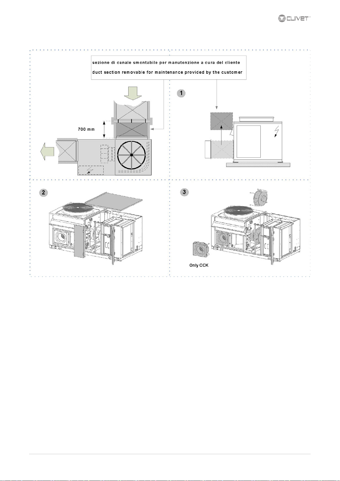
Remove the pre-lter by lifting it of about 1 cm and remove it as shown in gure.
1. Position the lter to be washed on a support to facilitate work.
2. Prepare a tank with a solution of B01212 detergent and water at 1÷20.
3. Immerse the lter in this solution.
4. Ensure the solution covers the entire lter.
5. A slight chemical reaction is noticed within 2÷3 minutes with the development of foam. Wait 3 or 4 minutes.
6. Rinse the lter with a jet of water or using a low-pressure water jet machine.
7. Leave the electrostatic cells to dry in a hot room or directly in the sun for a few hours. Keep the cells lifted from the ground using two
metal or wooden laths.
8. Check the ionisation wires before remounting the lter.
The cleaner can be used to clean about 20 lters.
Can be recovered and placed in plastic containers closed; the air oxidizes the cleaner and reduces its eectiveness.
IONISATION WIRES
The impurities can determine oxidation or scaling on the wires, which can be removed using a cloth soaked in alcohol or an abrasive scourer
with very ne grain.
Due to the high voltage powering them, the ionisation wires are subject to wear.
To foresee a yearly replacement OF ALL WIRES avoids unexpected breaks.
In case of break:
1. remove all wire pieces present in the cell and remove the springs stretching the wire
2. hook the spring to the wire eyelet
3. grip the ionisation wire with curved beaks pliers
4. hook the top of the spring with the open eyelet to the wire stretcher rod of the electrostatic cell
5. keeping the ionisation wire stretched, with the other hand hook it to the other wire stretching rod, always by means of the curved beaks
pliers
M06K40A18-00 CKN-XHE2i 7.1-14.2 46

10.2 F7 Highly ecient lters
The pocket lters are not renewable, once dirty they must be replaced
1. Open the access panel
2. Delicately remove the lter avoiding dirtying the area below
3. Insert the new lters, with the pockets vertically
4. Close the panel
5. Dispose of the old lters sending them to specialised recycling or collection centres (keep to the standards in force)
4 CKN-XHE2i 7.1-14.2 M06K40A18-00
10.3 Immersed electrode humidier
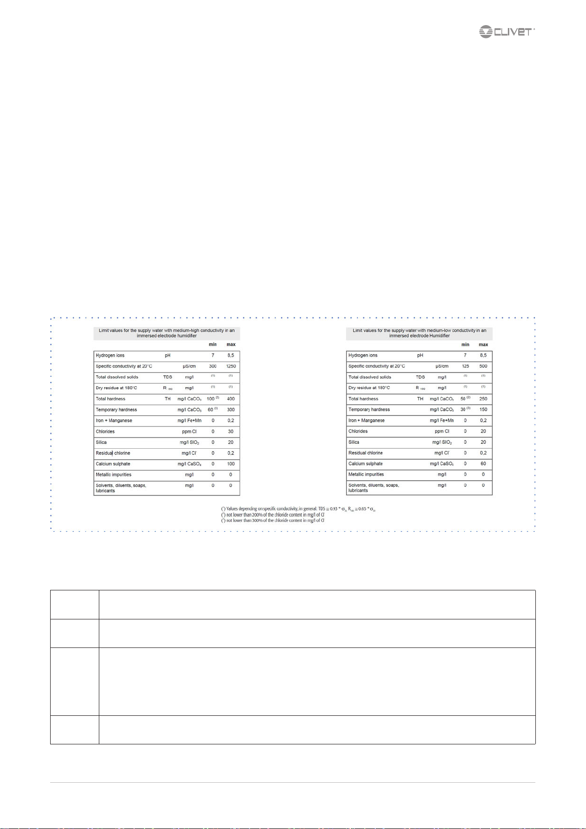
SUPPLY WATER
The humidier must be supplied with mains water having the following features:
pressure between 0.1 and 0.8 Mpa (1 – 8 bar)
•
temperature between 1 and 40°C
•
Do not use:
water treated with softeners: it can corrode the electrodes and form foam with possible faults/malfunctionings
•
pit, industrial or potentially polluted (chemically or bacteriologically) water
•
disinfectants or anti-corrosive substances mixed with water, as potentially irritating
•
Supplying the humidier with water treated with reverse osmosis ltering system gives the following advantages:
reduces limescale deposits
•
reduces energy consumptions
•
reduces maintenance costs
•
increases the humidier’s duration
•
Check that the lter guarantees a water ow rate higher than the ow rate of the installed humidier.
DRAINAGE WATER
It can reach a temperature of 100°C
It contains the same substances of the supply water but in higher concentration.
As it is not toxic, it can be disposed of with white waters.
Periodical checks
Do not use solvents or detergents to clean the plastic components.
For descaling use a vinegar or acetic acid solution at 20%, subsequently rinsing with water.
15 days
90 days
1 year
5 years
M06K40A18-00 CKN-XHE2i 7.1-14.2 4
Cylinder:
not over 300 hours of work
checking operation, general state, no leaks
Cylinder:
not over 1000 hours of work
checking operation, general state, no leaks, any replacement
Cylinder:
not over 2500 hours of work (disposable cylinders)
Load solenoid valve replacement:
disconnect electric power supply, dismantle valve, clean the lter
Drain solenoid valve:
disconnect electric power supply, remove reel and dismantle valve body and any impurity and rinse
The power supply bowl, piping:
check they are free and without impurities
Cylinder:
not over 10000 hours of work (inspectional cylinders)
replacement

Humidier cylinder drainage
Cylinder must be drained in these situations:
cleaning of the cylinder
•
emptying of the cylinder to avoid ice forming
•
replacement of the cylinder
•
The manual drainage is carried out by means of selector SA7: see ELECTRIC CONNECTIONS chapter.
Replacement of the cylinder
To remove the cylinder:
completely drain the water
•
interrupt power supply voltage of humidier by means of the unit isolator
•
remove the vapour pipe from the cylinder
•
disconnect the electric connections of the electrodes and remove the pins from the high level electrodes
•
loosen the ring nut to remove the pipe unions and the lter (when lter is outside the cylinder)
•
lift the cylinder to remove it
•
Before mounting it:
the lter body does not require replacing, wash it with water and remount it on the new cylinder, using the new gasket provided with
•
the latter
check the seal gasket between the cylinder and the drain unit
•
remount the cylinder repeating the operations in reverse order
•
4 CKN-XHE2i 7.1-14.2 M06K40A18-00

10.4 Modulating condensation gas heating module
System maintenance booklet
It must be kept in the place of installation of the unit
•
It must be lled-in upon commissioning
•
It must be updated with the results of the periodical checks, of the routine and extraordinary maintenance interventions.
•
Gas connection
Read the gas heating module manual.
•
Connection must be carried out by qualied personnel.
•
use certied components and comply with the local standards in force
•
install on the gas connection: tap, large section lter and anti-vibration joint
•
check the supply pressure is correct and stable, in particular where more uses are inserted on the same line.
•
The heating module includes:
hot air generator with condensation and integrated modulating adjustment, powered with methane gas
•
kit for transformation of power with liqueed petroleum gas (LPG)
•
kit of steel chimney for exhaust fumes
•
All the control and safety devices
•
1. GAS COCK
2. GAS FILTER (LARGE SECTION)
3. ANTI-VIBRATION JOINT
4. GAS FILTER (SMALL SECTION)
5. SAFET GAS SOLENOID VLAVE
6. PRESSURE STABILISER
7. MAIN GAS BURNER SOLENOID VALVE
8. PILOT BURNER GAS SOLENOID VALVE
M06K40A18-00 CKN-XHE2i 7.1-14.2 5

Flue stack assembly
5 CKN-XHE2i 7.1-14.2 M06K40A18-00

10.5 Gas heating module with 2-stage control
System maintenance booklet
It must be kept in the place of installation of the unit
•
It must be lled-in upon commissioning
•
It must be updated with the results of the periodical checks, of the routine and extraordinary maintenance interventions.
•
Gas connection
Read the gas heating module manual.
•
Connection must be carried out by qualied personnel.
•
use certied components and comply with the local standards in force
•
install on the gas connection: tap, large section lter and anti-vibration joint
•
check the supply pressure is correct and stable, in particular where more uses are inserted on the same line.
•
The heating module includes:
hot air generator with condensation and integrated modulating adjustment, power with methane gas
•
kit for transformation of power with liqueed petroleum gas (LPG)
•
kit of steel chimney for exhaust fumes
•
All the control and safety devices
•
1. GAS COCK
2. GAS FILTER (LARGE SECTION)
3. ANTI-VIBRATION JOINT
4. GAS FILTER (SMALL SECTION)
5. SAFET GAS SOLENOID VLAVE
6. PRESSURE STABILISER
7. MAIN GAS BURNER SOLENOID VALVE
8. PILOT BURNER GAS SOLENOID VALVE
M06K40A18-00 CKN-XHE2i 7.1-14.2 5
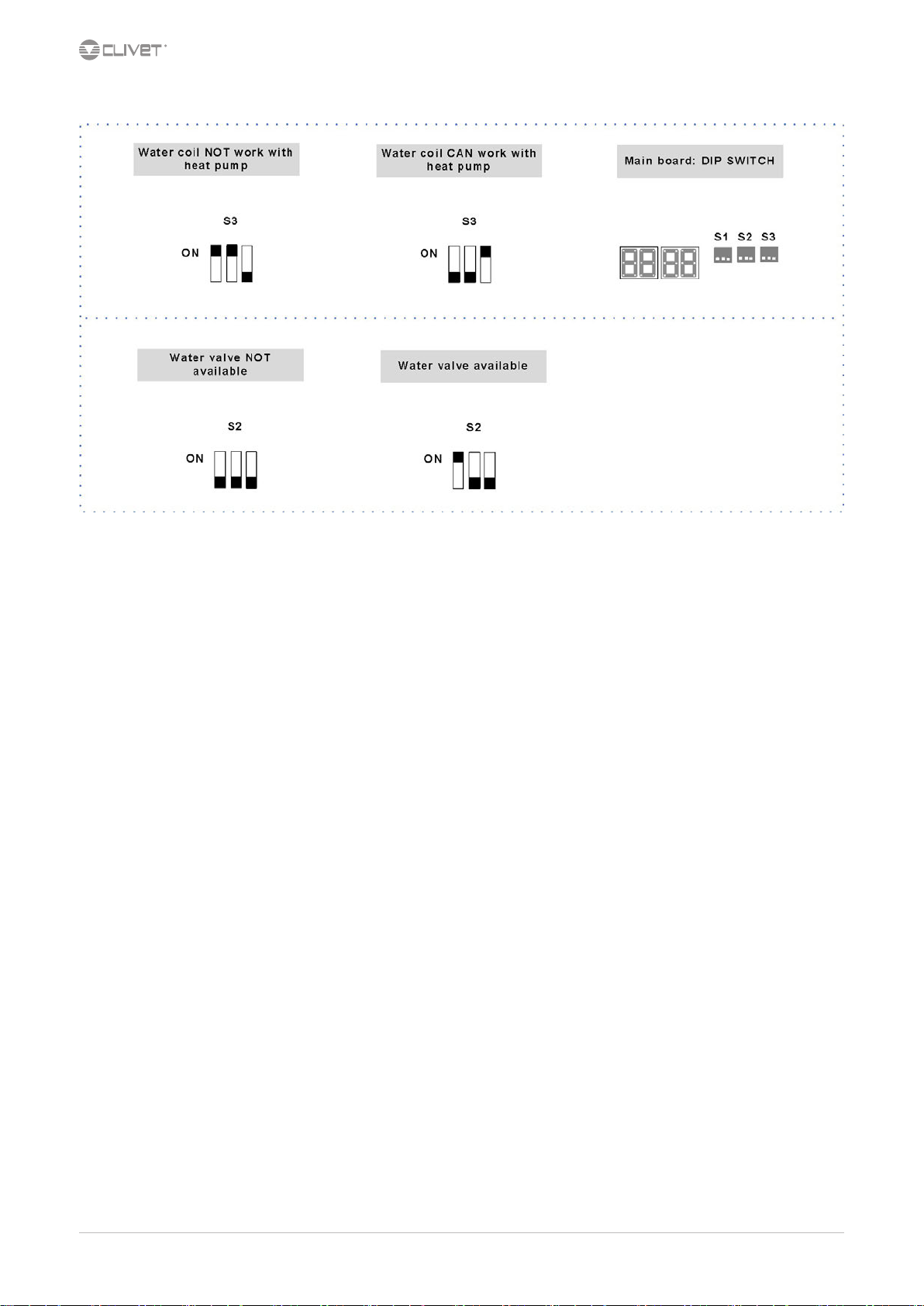
10.6 Hot water coil
5 CKN-XHE2i 7.1-14.2 M06K40A18-00

11 Decommissioning
11.1 Disconnecting
Only authorised personnel must disconnect the unit.
Avoid leak or spills into the environment.
Before disconnecting the unit, the following must be recovered, if present:
refrigerant gas
•
anti-freeze solutions in the water circuit
•
Awaiting dismantling and disposal, the unit can also be stored outdoors, if the electrical, cooling and water circuits of the unit have 100%
integrity and are isolated, bad weather and rapid change in temperature will not result in any environmental impact.
11.2 Dismantling and disposal
The unit must always be sent to authorised centres for dismantling and disposal.
When dismantling the unit, the fan, the motor and the coil, if operating, may be recovered by the specialist centres for reuse.
All the materials must be recovered or disposed of in compliance with the corresponding national standards in force.
For further information on the decommissioning of the unit, contact the manufacturer.
11.3 Directive EC RAEE
The units covered by the legislation in question are marked with the symbol on the side.
With the aim of protecting the environment, all of our units are produced in compliance with Directive EC on waste electrical and electronic
equipment (RAEE).
The potential eects on the environment and on human health due to the presence of hazardous substances are shown in the use and
maintenance manual in the section on residual risks.
Information in addition to that indicated below, if required, can be obtained from the manufacturer/distributor/importer, who are responsible
for the collection/handling of waste originating from equipment covered by EC-RAEE. This information is also available from the retailer who
sold this appliance or from the local authorities who handle waste.
Directive EC-RAEE requires disposal and recycling of electrical and electronic equipment as described therein to be handled through
appropriate collection, in suitable centres, separate from collection for the disposal of mixed urban waste.
The user must not dispose of the unit at the end of its life cycle as urban waste, it must instead be handed over to appropriate collection
centres as set forth by current standards or as instructed by the distributor.
M06K40A18-00 CKN-XHE2i 7.1-14.2 54

12 Residual risks
General description
In this section the most common situations are indicated,as these cannot be
controlled by the manufacturer and could be a source of risk situations for
people or things.
Danger zone
This is an area in which only an authorised operator may work.
The danger zone is the area inside the unit which is accessible only with the
deliberate removal of protections or parts thereof.
Handling
The handling operations, if implemented without all of the protection
necesssary and without due caution, may cause the drop or the tipping of
the unit with the consequent damage, even serious, to persons, things or the
unit itself.
Handle the unit following the instructions provided in the present manual regarding the packaging and in compliance with the local regulations in force.
Should the refrigerant leak please refer to the refrigerant “Safety sheet”.
Installation
The incorrect installation of the unit could cause water leaks, condensate
accumulation, leaking of the refrigerant, electric shock, poor operation or
damage to the unit itself.
Check that the installation has been implemented by qualied technical
personnel only and that the instructions contained in the present manual
and the local regulations in force have been adhered to.
The installation of the unit in a place where even infrequent leaks of inammable gas and the accumulation of this gas in the area surrounding the area
occur could cause explosions or res.
Carefully check the positioning of the unit.
The installation of the unit in a place unsuited to support its weight and/or
guarantee adequate anchorage may result in consequent damage to things,
people or the unit itself.
Carefully check the positioning and the anchoring of the unit.
Easy access to the unit by children, unauthorised persons or animals may be
the source of accidents, some serious.
Install the unit in areas which are only accessible to authorised person and/or
provide protection against intrusion into the danger zone.
General risks
Smell of burning, smoke or other signals of serious anomalies may indicate a
situation which could cause damage to people, things or the unit itself.
Electrically isolate the unit (yellow-red isolator).
Contact the authorised service centre to identify and resolve the problem at
the source of the anomaly.
Accidental contact with exchange batteries, compressors, air delivery tubes
or other components may cause injuries and/or burns.
Always wear suitable clothing including protective gloves to work inside the
danger zone.
Maintenance and repair operations carried out by non-qualied personnel
may cause damage to persons, things or the unit itself.
Always contact the qualied assistance centre.
Failing to close the unit panels or failure to check the correct tightening of all
of the panelling xing screws may cause damage to persons, things or the
unit itself.
Periodically check that all of the panels are correctly closed and xed.
If there is a re the temperature of the refrigerant could reach values that increase the pressure to beyond the safety valve with the consequent possible
projection of the refrigerant itself or explosion of the circuit parts that remain
isolated by the closure of the tap.
Do not remain in the vicinity of the safety valve and never leave the refrigerating system taps closed.
Electric parts
An incomplete attachment line to the electric network or with incorrectly
sized cables and/or unsuitable protective devices can cause electric shocks,
intoxication, damage to the unit or res.
Carry out all of the work on the electric system referring to the electric layout
and the present manual ensuring the use of a system thereto dedicated.
An incorrect xing of the electric components cover may lead to the entry of
dust, water etc inside and may consequently electric shocks, damage to the
unit or res.
Always x the unit cover properly.
When the metallic mass of the unit is under voltage and is not correctly
connected to the earthing system it may be as source of electric shock and
electrocution.
Always pay particular attention to the implementation of the earthing
system connections.
Contact with parts under voltage accessible inside the unit after the removal
of the guards can cause electric shocks, burns and electrocution.
Open and padlock the general isolator prior to removing the guards and
signal work in progress with the appropriate sign.
Contact with parts that could be under voltage due to the start up of the unit
may cause electric shocks, burns and electrocution.
When voltage is necessary for the circuit open the isolator on the attachment
line of the unit itself, padlock it and display the appropriate warning sign.
Moving parts
Contact with the transmissions or with the fan aspiration can cause injuries.
Prior to entering the inside of the unit open the isolater situated on the connection line of the unit itself, padlock and display the appropriate warning
sign.
Contact with the fans can cause injury.
Prior to removing the protective grill or the fans, open the isolator on the
attachment line of the unit itself, padlock it and display the appropriate
warning sign.
Refrigerant
The intervention of the safety valve and the consequent expulsion of the gas
refrigerant may cause injuries and intoxication.
Always wear suitable clothing including protective gloves and eyeglasses for
operations inside the danger zone.
Should the refrigerant leak please refer to the refrigerant “Safety sheet”.
Contact between open ames or heat sources with the refrigerant or the
heating of the gas circuit under pressure (e.g. during welding operations)
may cause explosions or res.
Do not place any heat source inside the danger zone.
The maintenance or repair interventions which include welding must be
carried out with the system o.
Hydraulic parts
Defects in tubing, the attachments or the removal parts may cause a leak
or water projection with the consequent damages to people, things or
shortcircuit the unit.
5 CKN-XHE2i 7.1-14.2 M06K40A18-00

General technical data
Size 7.1 10.1 14.2
Cooling
Cooling capacity 1 kW 20,6 30,4 45,7
Sensible capacity 1 kW 16,5 24,6 35,9
Compressor power input 1 kW 5,27 8,28 11,5
EER 1 3,91 3,67 3,97
Heating
Heating capacity 2 kW 20,9 29,8 43,8
Compressor power input 2 kW 5,08 7,24 9,89
COP 2 4,11 4,12 4,43
Compressor
Type of compressors 3 Rot Scroll Rot
No. of compressors Nr 1 1 2
Std Capacity control steps Nr 20-100% 20-100% 20-100%
Refrigerant charge (C1) 4 kg 7,0 10,0 13,0
Refrigeration circuits Nr 1 1 1
Air Handling Section Fans (Supply)
Type of supply fan 5 RAD RAD RAD
Number of supply fans Nr 1 1 1
Fan diameter mm 450 500 560
Type of motor 6 EC Brushless EC Brushless EC Brushless
Supply airow l/s 1111 1667 2500
3
Supply airow m
Installed unit power kW 1,0 2,6 2,9
Max. static pressure supply fan 7 Pa 380 680 510
Fans (Exhaust)
Type of exhaust fan 5 RAD RAD RAD
Number of exhaust fans 8 Nr 1 1 1
Fan diameter 8 mm 355 355 450
Type of motor 6 EC Brushless EC Brushless EC Brushless
Installed unit power 8 kW 0,9 0,9 1,0
External Section Fans
Type of fans 9 AX AX AX
Number of fans Nr 1 1 1
Fan diameter mm 750 750 780
Fan RPM 6 EC Brushless EC Brushless EC Brushless
Standard airow l/s 2361 3500 5833
Installed unit power kW 0,65 0,75 1,5
Connessioni
Scarico condensa mm 20 20 20
Power supply
Standard power supply V 400/3/50+N 400/3/50+N 400/3/50+N
Performance data are referred to operation with 30% of fresh air intake and same amount of air exhaust. (conguration CCK)
1. Ambient air at 27°C/19°C W.B.. external exchanger entering air temperature 35°C. EER referred only to compressors
2. Ambient air 20°C D.B. Outdoor air 7°C D.B./6°C W.B.. COP referred only to compressors
3. ROT = compressore rotativo; SCROLL = scroll compressor
4. Indicative values for standard units with possible +/-10% variation. The actual data are indicated on the label of the unit
5. RAD = radial fan
6. EC Electronic switching motor
7. Net outside static pressure to win the outlet and intake onboard pressure drops
8. Conguration for fresh air supply with exhaust and extraction
9. AX = axial fan
/h 4000 6000 9000
M06K10A18-00 CKN-XHE2i 7.1-14.2 56

Operating range (Cooling)
Operating range (Heating)
The limits are meant as an indication and they have been calculated by considering:
- general and non specic sizes,
- standard airow,
- non-critical positioning of the unit and correct operating and maintenance of the unit,
- operating at full load
To verify the operation eld of the operating units with percentages of external air, always
calculate the Tm mixing temperature at the internal heat exchanger input.
TM = INTERNAL EXCHANGER ENTERING AIR TEMPERATURE
temperature measured with wet bulb (W.B.=WET BULB)
TEXT = INLET AIR TEMPERATURE IN THE EXTERNAL EXCHANGER
dry bulb measured temperature (D.B.=DRY BULB)
Within the operating range, the unit can operate at a part load to maximaze the energy
eciency
1. Standard operating range
2. Operation eld of the unit in FREE-COOLING mode
WET BULB TEMPERATURE - EXAMPLE
The limits are meant as an indication and they have been calculated by considering:
- general and non specic sizes,
- standard airow,
- non-critical positioning of the unit and correct operating and maintenance of the
unit,
- operating at full load
To verify the operation eld of the operating units with percentages of external air,
always calculate the Tm mixing temperature at the internal heat exchanger input.
TM = INTERNAL EXCHANGER ENTERING AIR TEMPERATURE
temperature measured with wet bulb (W.B.=WET BULB)
TEXT = INLET AIR TEMPERATURE IN THE EXTERNAL EXCHANGER
dry bulb measured temperature (D.B.=DRY BULB)
Within the operating range, the unit can operate at a part load to maximaze the
energy eciency
1. Standard operating range
2. Range in which the unit operation is allowed only for a limited period (max
1 hour)
In extended operating mode, in heat pump operation with an outdoor air
temperature of less than 6°C, the unit performs defrosts by reversing the cycle, so as
to eliminate the ice that forms on the surfaces of the outside exchanger; in addition,
in the event of negative temperatures, the water resulting from the defrosts must be
drained so as to avoid the accumulation of ice near the base of the unit. Make sure
that this does not constitute a danger for people or things.
With an outdoor air temperature between –10°c and –20°c install the following
options:
• 2 rows hot water coil
• Combustion module
• Electrical panel anti-freeze protection
5
CKN-XHE2i 7.1-14.2 M06K10A18-00

Sound levels
Sound power level (dB) Sound
Size
63 125 250 500 1000 2000 4000 8000 dB(A) dB(A)
7.1 69 73 76 77 77 75 70 74 82 65
10.1 77 75 77 79 79 77 71 75 84 66
14.2 73 78 79 82 81 79 74 78 86 68
The sound levels are referred to unit operating at full load in nominal conditions. The sound pressure level is referred at a distance of 1 m. from the ducted unit surface operating in free field conditions. External static pressure 50 Pa.
(standard UNI EN ISO 9614-2)
Measures are according to UNI EN ISO 9614-2 regulations, with respect to the EUROVENT 8/1 certication, which provides for a tolerance of 3 dB(A) on the sound power level, which is the only acoustic data to be considered binding. If unit is
set without Axitop, the sound power level presents an increase up to 3 dB(A).
Please note that when the unit is installed in conditions different from nominal test conditions (e.g. near walls or obstacles in general), the sound levels may undergo substantial variations.
Octave band (Hz)
power
level
Sound
pressure
level
M06K10A18-00 CKN-XHE2i 7.1-14.2 5

Dimensional drawings
Size 7.1 - Version CAK/CBK/CCK
DAA6K0001_7.1_0_REV00
Data/Date 06/11/2017
1. Compressor compartment
2. Electrical panel
3. Power input
4. Humidier connections
5. Condensate drain
6. H2O heating coil output Φ 3/4”
7. H2O heating coil input Φ 3/4”
8. Re-heating coil (optional)
9. Internal exchanger
10. External exchanger
11. H2O heating coil (optional) or heating elements (optional)
12. Electrostatic lters or F7 (optional)
13. G4 air lters (standard)
14. Electric fan (supply-return)
15. Exhaust electric fan (version CCK only)
16. Lifting brackets (removable)
17. Over pressure damper exhaust (version CCK only)
18. Access for inspection coil, lters, hesting elements
19. Access for inspection of the bleed valve (hot water coil)
20. Duct section removable for maintenance provided by the customer
21. Fresh air intake cap (only version CBK-CCK)
(R) Air return
(M) Air supply
(AE) Fresh air intake
(ES) Air exhaust (only version CCK)
(H1) Wall with same height as unit on a maximun of three side
(**) Minimun suggested clearance
(*) Vibration mounts position
Weight distribution of full re-circulation (CAK) / Recirculation and renewal air (CBK) conguration
Size 7.1
W1 Supporting Point kg 98
W2 Supporting Point kg 122
W3 Supporting Point kg 96
W4 Supporting Point kg 100
Shipping weight kg 452
Weight distribution of full re-circulation, renewal air and exhaust (CCK) conguration
Size 7.1
W1 Supporting Point kg 102
W2 Supporting Point kg 126
W3 Supporting Point kg 101
W4 Supporting Point kg 105
Shipping weight kg 470
The presence of optional accessories may result in a substantial variation of the weights shown in the table.
5
CKN-XHE2i 7.1-14.2 M06K10A18-00

Dimensional drawings
Size 10.1 - Version CAK/CBK/CCK
DAA6K0002_10.1_0_REV00
Data/Date 06/11/2017
1. Compressor compartment
2. Electrical panel
3. Power input
4. Humidier connections
5. Condensate drain
6. H2O heating coil outpu Φ 1”
7. H2O heating coil input Φ 1”
8. Re-heating coil (optional)
9. Internal exchanger
10. External exchanger
11. H2O heating coil (optional) or heating elements (optional)
12. Electrostatic lters or F7 (optional)
13. G4 air lters (standard)
14. Electric fan (supply-return)
15. Exhaust electric fan (version CCK only)
16. Lifting brackets (removable)
17. Over pressure damper exhaust (version CCK only)
18. Access for inspection coil, lters, hesting elements
19. Access for inspection of the bleed valve (hot water coil)
20. Duct section removable for maintenance provided by the customer
21. Fresh air intake cap (only version CBK-CCK)
(R) Air return
(M) Air supply
(AE) Fresh air intake
(ES) Air exhaust (only version CCK)
(H1) Wall with same height as unit on a maximun of three side
(**) Minimun suggested clearance
(*) Vibration mounts position
Weight distribution of full re-circulation (CAK) / Recirculation and renewal air (CBK) conguration
Size 10.1
W1 Supporting Point kg 132
W2 Supporting Point kg 107
W3 Supporting Point kg 131
W4 Supporting Point kg 126
Shipping weight kg 532
Weight distribution of full re-circulation, renewal air and exhaust (CCK) conguration
Size 10.1
W1 Supporting Point kg 138
W2 Supporting Point kg 113
W3 Supporting Point kg 137
W4 Supporting Point kg 132
Shipping weight kg 556
The presence of optional accessories may result in a substantial variation of the weights shown in the table.
M06K10A18-00 CKN-XHE2i 7.1-14.2
6

Dimensional drawings
Size 14.2 - Version CAK/CBK/CCK
DAA6K0003_14.2_0_REV00
Data/Date 06/11/2017
1. Compressor compartment
2. Electrical panel
3. Power input
4. Humidier connections
5. Condensate drain
6. H2O heating coil outpuΦ 1” 1/4
7. H2O heating coil input Φ 1” 1/4
8. Re-heating coil (optional)
9. Internal exchanger
10. External exchanger
11. H2O heating coil (optional) or heating elements (optional)
12. Electrostatic lters or F7 (optional)
13. G4 air lters (standard)
14. Electric fan (supply-return)
15. Exhaust electric fan (version CCK only)
16. Lifting brackets (removable)
17. Over pressure damper exhaust (version CCK only)
18. Access for inspection coil, lters, hesting elements
19. Access for inspection of the bleed valve (hot water coil)
20. Duct section removable for maintenance provided by the customer
21. Fresh air intake cap (only version CBK-CCK)
(R) Air return
(M) Air supply
(AE) Fresh air intake
(ES) Air exhaust (only version CCK)
(H1) Wall with same height as unit on a maximun of three side
(**) Minimun suggested clearance
(*) Vibration mounts position
Weight distribution of full re-circulation (CAK) / Recirculation and renewal air (CBK) conguration
Size 14.2
W1 Supporting Point kg 175
W2 Supporting Point kg 127
W3 Supporting Point kg 171
W4 Supporting Point kg 162
Shipping weight kg 685
Weight distribution of full re-circulation, renewal air and exhaust (CCK) conguration
Size 14.2
W1 Supporting Point kg 183
W2 Supporting Point kg 137
W3 Supporting Point kg 180
W4 Supporting Point kg 170
Shipping weight kg 720
The presence of optional accessories may result in a substantial variation of the weights shown in the table.
6
CKN-XHE2i 7.1-14.2 M06K10A18-00

Dimensional drawings
Size 7.1 - Version CAK/CBK/CCK - Gas heating module 35/53 kW
DAA6K0004_7.1_GC01_GD13_0 REV00
Data/Date 16/11/2017
1. Compressor compartment
2. Electrical panel
3. Power input
4. Humidier connections
5. Condensate drain
6. Gas connection
7. Condensate drain (only for condensation gas heating module)
8. Re-heating coil (optional)
9. Internal exchanger
10. External exchanger
11. Resistenze elettriche (optional)
12. Electrostatic lters or F7 (optional)
13. G4 air lters (standard)
14. Electric fan (supply-return)
15. Exhaust electric fan (version CCK only)
16. Lifting brackets (removable)
17. Over pressure damper exhaust (version CCK only)
18. Access for inspection coil, lters, hesting elements
19. Duct section removable for maintenance provided by the customer
20. Fresh air intake cap (only version CBK-CCK)
21. Gas module
(R) Air return
(M) Air supply
(AE) Fresh air intake
(ES) Air exhaust (only version CCK)
(H1) Wall with same height as unit on a maximun of three side
(**) Minimun suggested clearance
(*) Vibration mounts position
Weight distribution of full re-circulation (CAK) / Recirculation and renewal air (CBK) conguration
Size 7.1
W1 Supporting Point kg 136
W2 Supporting Point kg 167
W3 Supporting Point kg 141
W4 Supporting Point kg 145
Shipping weight kg 625
Weight distribution of full re-circulation, renewal air and exhaust (CCK) conguration
Size 7.1
W1 Supporting Point kg 140
W2 Supporting Point kg 172
W3 Supporting Point kg 145
W4 Supporting Point kg 150
Shipping weight kg 643
The presence of optional accessories may result in a substantial variation of the weights shown in the table.
M06K10A18-00 CKN-XHE2i 7.1-14.2
6
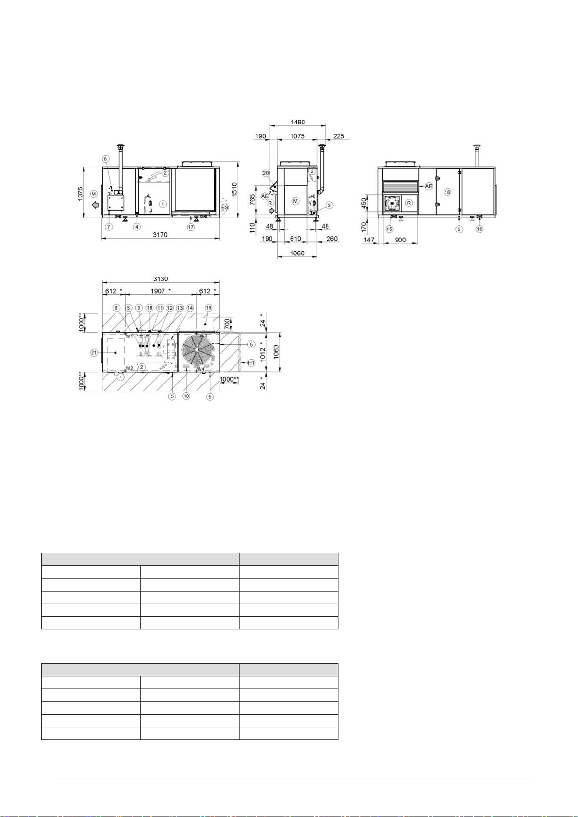
Dimensional drawings
Size 10.1 - Version CAK/CBK/CCK - Gas heating module 35/53 kW
DAA6K0005_10.1_GC01_GD13_0 REV00
Data/Date 06/11/2017
1. Compressor compartment
2. Electrical panel
3. Power input
4. Humidier connections
5. Condensate drain
6. Gas connection
7. Condensate drain (only for condensation gas heating module)
8. Re-heating coil (optional)
9. Internal exchanger
10. External exchanger
11. Resistenze elettriche (optional)
12. Electrostatic lters or F7 (optional)
13. G4 air lters (standard)
14. Electric fan (supply-return)
15. Exhaust electric fan (version CCK only)
16. Lifting brackets (removable)
17. Over pressure damper exhaust (version CCK only)
18. Access for inspection coil, lters, hesting elements
19. Duct section removable for maintenance provided by the customer
20. Fresh air intake cap (only version CBK-CCK)
21. Gas module
(R) Air return
(M) Air supply
(AE) Fresh air intake
(ES) Air exhaust (only version CCK)
(H1) Wall with same height as unit on a maximun of three side
(**) Minimun suggested clearance
(*) Vibration mounts position
Weight distribution of full re-circulation (CAK) / Recirculation and renewal air (CBK) conguration
Size 10.1
W1 Supporting Point kg 180
W2 Supporting Point kg 148
W3 Supporting Point kg 173
W4 Supporting Point kg 168
Shipping weight kg 705
Weight distribution of full re-circulation, renewal air and exhaust (CCK) conguration
Size 10.1
W1 Supporting Point kg 186
W2 Supporting Point kg 154
W3 Supporting Point kg 179
W4 Supporting Point kg 174
Shipping weight kg 729
The presence of optional accessories may result in a substantial variation of the weights shown in the table.
6
CKN-XHE2i 7.1-14.2 M06K10A18-00

Dimensional drawings
Size 14.2 - Version CAK/CBK/CCK - Gas heating module 35/100 kW
DAA6K0006_14.2_GC01_GD15_0 REV00
Data/Date 06/11/2017
1. Compressor compartment
2. Electrical panel
3. Power input
4. Humidier connections
5. Condensate drain
6. Gas connection
7. Condensate drain (only for condensation gas heating module)
8. Re-heating coil (optional)
9. Internal exchanger
10. External exchanger
11. Resistenze elettriche (optional)
12. Electrostatic lters or F7 (optional)
13. G4 air lters (standard)
14. Electric fan (supply-return)
15. Exhaust electric fan (version CCK only)
16. Lifting brackets (removable)
17. Over pressure damper exhaust (version CCK only)
18. Access for inspection coil, lters, hesting elements
19. Duct section removable for maintenance provided by the customer
20. Fresh air intake cap (only version CBK-CCK)
21. Gas module
(R) Air return
(M) Air supply
(AE) Fresh air intake
(ES) Air exhaust (only version CCK)
(H1) Wall with same height as unit on a maximun of three side
(**) Minimun suggested clearance
(*) Vibration mounts position
Weight distribution of full re-circulation (CAK) / Recirculation and renewal air (CBK) conguration
Size 14.2
W1 Supporting Point kg 249
W2 Supporting Point kg 191
W3 Supporting Point kg 235
W4 Supporting Point kg 226
Shipping weight kg 951
Weight distribution of full re-circulation, renewal air and exhaust (CCK) conguration
Size 14.2
W1 Supporting Point kg 258
W2 Supporting Point kg 200
W3 Supporting Point kg 243
W4 Supporting Point kg 235
Shipping weight kg 986
The presence of optional accessories may result in a substantial variation of the weights shown in the table.
M06K10A18-00 CKN-XHE2i 7.1-14.2
64


CLIVET SPA
A Group Company of
Via Camp Lonc 25, Z.I. Villapaiera - 32032 Feltre (BL) - Italy
Tel. + 39 0439 3131 - Fax + 39 0439 313300 - info@clivet.it
CLIVET GROUP UK Limited
4 Kingdom Close, Segensworth East - Fareham, Hampshire - PO15 5TJ - United Kingdom
Tel. + 44 (0) 1489 572238 - Fax + 44 (0) 1489 573033 - enquiries@clivetgroup.co.uk
CLIVET GROUP UK Limited (Operations)
Units F5&F6 Railway Triangle Ind Est, Walton Road - Portsmouth, Hampshire - PO6 1TG - United Kingdom
Tel. +44 (0) 2392 381235 - Fax. +44 (0) 2392 381243 - service@clivetgroup.co.uk
CLIVET ESPAÑA S.A.U.
C/ Bac de Roda, 36- - 08019 Barcelona - España
Tel: +34 93 8606248 - Fax +34 93 8855392 - info@clivet.es
Av.Manoteras Nº 38, Ocina C303 - 28050 Madrid - España
Tel. +34 91 6658280 - Fax +34 91 6657806 - info@clivet.es
CLIVET GmbH
Hummelsbütteler Steindamm 84, 22851 Norderstedt - Germany
Tel. + 49 (0) 40 32 59 57-0 - Fax + 49 (0) 40 32 59 57-194 - info.de@clivet.com
CLIVET RUSSIA
Elektrozavodskaya st. 24, oce 509 - 107023, Moscow, Russia
Tel. + 74956462009 - Fax + 74956462009 - info.ru@clivet.com
CLIVET MIDEAST FZCO
Dubai Silicon Oasis (DSO), High Bay Complex, Oce N. 20, PO BOX 342009, Dubai, UAE
Tel. + 9714 3208499 - Fax + 9714 3208216 - info@clivet.ae
CLIVET AIRCONDITIONING SYSTEMS PRIVATE LIMITED
4BA, Gundecha Onclave, Kherani Road - Sakinaka, Andheri (East) - Mumbai 400 072 - India
Tel. +91 22 6193 7000 - Fax +91 22 6193 7001 - info.in@clivet.com
www.clivet.com
www.clivetlive.com
 Loading...