

Page 1

CF
91-121-142-162-182-202-242
DUCTABLE HORIZONTAL RECESSED WATER TERMINAL UNIT
Installation and Use Manual
M42740M4-02 25/09/08
Page 2

Page 3

UNIT IDENTIFICATION........................................................................... 4
GENERAL WARNINGS ............................................................................ 5
RESIDUAL RISKS ................................................................................. 6
RECEPTION......................................................................................... 7
INSPECTION UPON RECEPTION................................................................................................................................. 7
STORAGE ......................................................................................................................................................................7
HANDLING .....................................................................................................................................................................7
POSITIONING ...................................................................................... 8
GENERAL.......................................................................................................................................................................8
FUNCTIONAL CLEARANCES........................................................................................................................................8
POSITIONING ................................................................................................................................................................8
WATER CONNECTIONS .......................................................................... 9
GENERAL.......................................................................................................................................................................9
AIR CONNECTIONS ..............................................................................10
FEATURES FOR DUCTS FOR TREATED AIR............................................................................................................10
ELECTRICAL CONNECTION ...................................................................11
GENERAL.....................................................................................................................................................................11
STANDARD UNIT ELECTRICAL DATA ....................................................................................................................... 11
CONNECTION TO THE MAINS ...................................................................................................................................11
START-UP..........................................................................................17
PRELIMINARY CHECKS..............................................................................................................................................17
AERAULIC SYSTEM .................................................................................................................................................... 17
WATER SYSTEM .........................................................................................................................................................17
ELECTRICAL SYSTEM ................................................................................................................................................17
VERIFy tensions – absorptions..................................................................................................................................... 17
REMOTE INPUT CONFIGURATIONS .........................................................................................................................18
SETTING THE SET-POINT ..........................................................................................................................................18
AIR FLOW CHECK .......................................................................................................................................................18
CONTROL ..........................................................................................19
ROUTINE MAINTENANCE.......................................................................29
SERVICES : PARTS SUBJECT TO INTERVENTION ......................................29
MAINTENANCE INSPECTIONS...................................................................................................................................31
PUT AT REST...............................................................................................................................................................31
TROUBLESHOOTING ............................................................................32
DECOMMISSIONING OF THE UNIT ...........................................................32
DISCONNECTING THE UNIT ......................................................................................................................................32
DISMANTLING AND DISPOSAL ..................................................................................................................................32
GENERAL TECHNICAL SPECIFICATIONS ..................................................33
DIMENSIONS ......................................................................................35
Page 4

UNIT IDENTIFICATION
SERIAL NUMBER LABEL
The units are identified by the serial number label shown here.
The label lists the type of unit (series and size), serial number, year
of manufacture, number of electrical diagram, main technical data,
logo and address of the manufacturer.
The label is placed on the unit, generally near the electrical panel
and also on the external panelling.
IT MUST NEVER BE REMOVED.
SERIAL NUMBER
This provides unique identification of the machine. It makes it
possible to trace the specific features of the unit and to identify the
components installed in it.
Without this number, it is not possible to identify with certainty the
spare parts that are specific to that unit.
When requesting assistance, always provide the type of machine
and the serial number.
Write them in the space below so that they are readily available
when needed.
Type of unit : _________________________________
Serial number : _________________________________
Wiring diagram : __________________________
Year of manufacture : ___________________________
COMMON CAUSES OF SHUTDOWN
air filter dirty
water filter dirty
external permissions (remote ON-OFF etc. )
water cut-off valves closed
M42740M4-02 02/10/08 page 4
Page 5

GENERAL WARNINGS
MANUAL PURPOSE
This manual has been designed to enable the unit to be
installed, started up and maintained correctly.
MANUAL INSTRUCTIONS
It is essential to observe these instructions.
The manufacturer declines all liability for any damage that
may be caused whether directly or indirectly to persons or
things if these instructions are not heeded.
MANUAL STORAGE
This manual and the unit’s wiring diagram should be
carefully stored so that they are readily available to the
operator when required.
EXPERT PERSONAL
The unit must be installed, tested and maintained by expert
personal who meet the relevant legal requirements (Italian
law No. 46 of 5/3/1990).
LOCAL SAFET REGULATION INSTALLATION
The installation must be performed observing the local
safety regulations.
POWER SUPPLY
Make sure the power supply conforms to the data on the
unit’s rating plate, located inside the door of the main
electrical panel.
PACKAGING
The packaging material (plastic bags, polystyrene foam,
nails, etc.) is potentially dangerous and should therefore be
kept away from children and recycled in compliance with
the local regulations in force.
MAINTENANCE
Before performing any service operations, cut off the power.
Perform the operations in conformity with the local
regulations in force.
PERIODICAL INSPECTIONS
Perform periodical inspections to locate possible loosened
or broken parts. If the repairs are not performed, there will
be a higher risk for things and peoples to become damaged
and injured.
FAULT – POOR OPERATION
Switch off the unit in the event of faults or poor operation.
REPAIR
Only have repairs carried out by a service centre authorised
by the manufacturer, and insist on the use of original spare
parts only.
Failure to comply with the above may compromise the
safety of the unit.
MODIFICATIONS
The manufacturer will not accept any responsibility, and the
warranty will lapse, in the event of electric and/or
mechanical modifications. Any modification which is not
formally authorized, and which does not respect the
instructions given in this manual, will cause the warranty to
lapse.
INTENDED USE
The unit must only be used for the specific purpose it was
designed :
The unit is designed for civil air-conditioning within the
limits defined in the technical bulletin and this manual.
Any use other than that specified does not imply any
commitment or constraint by the manufacturer in any way
whatsoever.
ADDITIONAL SAFETY PRECAUTIONS
This unit has been especially designed and manufactured
so to prevent any risk to persons and health hazard.
For this reason, design solutions fit to eliminate (where
possible) any cause of risk and sensibly reduce the
probability of danger have been adopted.
Please refer to the "Residual Risks" section of this manual
and strictly observe the behaviour prescriptions listed there
in order to prevent any possible risk that hasn’t been
possible to avoid in the design stage.
DATA UPDATING
The manufacturer may be able to modify the data without
prior notice as a consequence of constant improvements.
REGULA TIONS AND
CERTIFICATIONS
UNI EN ISO 9001 CERTIFICATION
Clivet S.p.A., in order to guarantee customer satisfaction,
has chosen the ISO 9001 Quality System as the reference
for all its business activities. This is demonstrated by the
company’s commitment to ongoing improvements in the
quality and reliability of its products; its sales, design,
purchasing, production and after-sales service activities are
the means used to reach such purpose.
CE MARK
Clivet products bear the CE mark, in compliance with the
requirements of the following EC directives, including the
latest amendments, and with the corresponding national
approximated legislation:
• 98/37/CE
• 89/336/CEE as modified by the directives 92/31/CEE and
93/68/CEE
• 73/23/CEE as modified by the directive 93/68/CEE
• 97/23/CE
M42740M4-02 02/10/08 page 5
Page 6

RESIDUAL RISKS
GENERAL
This section lists some of the more common situations
which, being beyond the control of the manufacturer, could
be a source of risk to persons or property.
DANGER AREA
The figure below highlights the area in which only
authorised personnel may operate.
• External danger zone, identified by a precise area
around the unit and its vertical projection on the
ground in the case of hanging unit.
• Internal danger zone, identified by the area that can
be entered only after having intentionally removed the
protecting panels or parts of these.
HANDLING
If handling operations are undertaken without adopting all
the necessary safety procedures and exercising due care,
the unit can fall or topple, causing damage — possibly
extremely serious — to persons and/or property, and to the
unit itself.
Ensure the unit is handled and manoeuvred as directed on
the packing and in the present manual, and in accordance
with local regulations.
In the event of refrigerant gas escaping, refer to the “Safety
datasheet” for the particular refrigerant.
INSTALLATION
Incorrect installation of the unit can result in water leaks,
accumulation of condensate, escape of refrigerant, electric
shocks, fire, as well as irregular operation or damage to the
unit itself.
Make certain that the installation is carried out only by a
qualified technician, also that the directions contained in
this manual are followed and local statutory regulations
observed.
In the event of the unit being installed in a site where there
is even the slightest risk of inflammable gas escapes and
consequently the possibility of such gases accumulating in
area around the unit, the risk of explosion and fire cannot
be discounted.
Take every care and precaution when selecting the
installation site.
Installation on a structure not able to bear the weight and/or
afford a secure anchorage of the equipment may cause the
unit to fall and/or topple, resulting in damage to persons or
property, or to the unit itself. Make certain that every care
and precaution is taken when positioning and securing the
unit.
If the unit is easily accessible to children, unauthorized
persons or animals, this is a situation that can give rise
accidents and injuries, perhaps serious. Install the unit in a
place where access is allowed only to authorized persons,
or install barriers or guards preventing unauthorized entry.
GENERAL RISKS
A smell of burning, smoke or other indications of serious
irregularity could signal the onset of situations liable to
cause damage to persons or property or to the unit itself.
Isolate the unit from the electrical power supply (red-andyellow) switch.
Contact an authorized service centre so that the source of
the problem can be identified and remedied.
Accidental contact with heat exchange coils, compressors,
pressure pipelines or other components can result in
wounding or burns, or both.
Always wear suitable clothing, including protective gloves,
when working in the danger area.
Maintenance or repairs carried out by unskilled operatives
can result in harm or damage to persons and property, or to
the unit itself. Always contact an authorized service centre.
Failure to close the panels of the unit, or to check that all
the fixing screws of the panels are properly tightened, can
result in harm or damage to persons or property, or to the
unit itself.
Verify periodically that all panels are closed and made
properly secure.
In the event of fire, the temperature of the refrigerant can
rise to the point that pressure will exceed safety levels and
perhaps cause fluid to be projected. It may also happen
that parts of the circuit isolated by closed valves will
explode.
Do not stand near safety valves, and never leave the valves
of the refrigerant circuit closed.
ELECTRICAL SYSTEM
If the power line connecting the unit to the a.c. supply is
incomplete, or if the connection is made with cables of
incorrect cross section and/or with insufficiently rated
protective devices, this can result in electric shock, toxicity
hazard, damage to the unit or fire.
All work on the electrical system should be carried out
referring to the wiring diagram and to the directions given in
this manual, and the system itself must be dedicated.
Failure to secure the cover enclosing electrical components
can lead to the infiltration of dust and water, ultimately
causing electric shocks, damage to the unit, or fire.
Always fasten the cover securely to the unit.
If live metal parts of the unit are not connected properly to
the earth system, they can cause electric shock or even
death by electrocution.
Make absolutely certain that the connection to the earth
system is made in accordance with correct practice.
Contact with live parts rendered accessible internally of the
unit when the guards are removed can result in electric
shock, burns or death by electrocution.
Before exposing these parts, make certain the isolating
switch on the power line to the unit is set to the OFF
position and padlocked, and post a warning sign.
Contact with parts that could become live when the unit is
started up can result in electric shock, burns or death by
electrocution.
When there is no need for circuits to be powered up, set the
isolating switch on the power line to the OFF position,
padlock it and post a warning sign.
MOVING PARTS
Contact with the fan rotors can cause injury.
Before removing the protective grilles or the fans
themselves, make certain the isolating switch on the power
line to the unit is set to the OFF position and padlocked,
and post a warning sign.
Before removing the protective grilles or the fans
themselves, make certain the isolating switch on the power
line to the unit is set to the OFF position and padlocked,
and post a warning sign.
WATER SYSTEM
Defects affecting pipelines, connections or valves and other
control componentry can result in water being leaked or
sprayed from the system, occasioning damage to property
or causing short circuits in the unit.
Make certain all hydraulic connections are securely made,
following the directions given in the present manual.
M42740M4-02 02/10/08 page 6
Page 7

RECEPTION
INSPECTION UPON RECEPTION
Check on arrival that the unit has not suffered damage
during transit and that it is complete in every part as
specified in the order. In the event of visible
damage/deficiencies being discovered, make a note
immediately on the delivery document with the comment:
CONDITIONAL ACCEPTANCE — CLEAR EVIDENCE OF
DEFICIENCIES/DAMAGE DURING TRANSIT
Inform both the supplier and the carrier of the details by fax
and by registered mail with advice of receipt not later than 8
days after taking consignment. Notifications sent after 8
days have elapsed will be ignored.
STORAGE
Shelter from: direct sunlight, rain, sand and wind
Temperature: maximum 60°C minimum -10°C
Maximum humidity: 90%
The respect of the instructions on the exterior side of the
packaging assures the physical and functional integrity of
the unit for the final user’s advantage.
It is recommended to:
• Handle carefully
• Keep in a dry place
• Avoid putting other objects on top of the unit (respect
the limits of levels of superimposition shown in the
package)
• Avoid placing the unit with thermoretractable protection
under the sun since the pressure of the circuits can
assume values which activate the safety valves.
LABELS / YELLOW BRACKETS SHOW THE LIFTING POINTS
HANDLING
The operation of handling the unit must be carried out
respecting the instructions of the safety norms in force
(Legislative Decree 626/94 and following modifications)
Before starting the handling operations:
• Value the critical points during handling (stairs, flights,
disconnected routes, doors, etc)
• Verify that the lifting capacity of the means used is
adequate to the unit weight
• Consider that the barycentre could be moved with
respect to the center of the unit
• Before starting to lift, verify that the unit is at a stable
balance
The following examples are indications; the choice of the
means and of the handling modes will depend on factors,
such as:
• The unit weight
• Type and overall dimensions of the unit
• Place and route for the handling (dirt yard, asphalted
square, etc)
• Condition of the place of destination (roof, square, etc)
• Handling distance characteristics (distances, flights,
steps, doors)
DO NOT LEAVE THE PACKAGES LOOSE DO NOT MOVE THE UNITS ALONE
FOR SEVERAL UNITS, USE A SUITABLE
CONTAINER
REMOVING THE PACKING
For removing the packaging, use specific personal
protection for the operator (gloves, glasses, etc.).
While removing the packaging, pay attention not to damage
the unit.
M42740M4-02 02/10/08 page 7
Check for any visible damage.
Dispose of the packaging by taking it to specialist collection
or recycling centres in accordance with local regulations.
Page 8

POSITIONING
GENERAL
For installing air-conditioning systems, it is necessary to
consider the following:
• the technical spaces necessary for the machine and
system
• the place where the machine will be installed
• the transport of thermal carrier fluids and relevant
connections to the unit:
o water
o air
If these aspects are not evaluated carefully, they can affect
the performances and the working life of the unit.
FUNCTIONAL CLEARANCES
When placing the unit, please respect the functional
clearances indicated in DIMENSIONS section.
The functional spaces need to be observed because of the
following:
• to guarantee the good operation of the unit
• to allow the performance of all maintenance operations
• to protect the authorized operators and exposed people
If more units are placed close to one another, the functional
spaces must be doubled.
1
2
POSITIONING
1. The units are designed for INDOOR installations,
performed in fixed positions and in areas accessible
only to qualified and authorized personnel
2. SAFETY VALVE (only if present on the unit) : the
installer is responsible for evaluating the opportunity of
installing drain tubes, in conformity with the local
regulations in force ( EN 378 )
3. Install the unit raised from the ground
4. avoid installations in places subject to flooding
5. It is recommended to put the unit on specific
antivibration devices
6. In the false ceiling, provide the indicated openings in
the functional spaces so as to allow access to the unit
for maintenance.
7. Leave free the surface projection of the unit and the
functional spaces so as to allow access with ladders
or other means.
(1) OUTLET SIDE VIEW
(SIZES 81-91-101-121)
(A) PANEL FOR MOTOR AND FAN
INSPECTION
(B) AIR FILTER
(C) ACCESS TRAP DOOR
(2) VIEW FROM THE TOP
(SIZES 81-91-101-121)
(D) PANEL FOR MOTOR AND FAN
INSPECTION
3
500
500
500
500
500
500
(E) PANEL FOR THERMOSTATIC
VALVE INSPECTION
(F) ELECTRICAL PANEL
(3) 3/4 FRONT VIEW
(SIZES 142-162-182-202-242)
M42740M4-02 02/10/08 page 8
Page 9

WATER CONNECTIONS
GENERAL
Piping must be designed with the least possible number of
bends and head variations. If the pressure chute of the
installation is above the useful prevalence of the pump, the
water delivery capacity is reduced as well as, as a
consequence, the thermal exchange and the yield.
INTERCEPTING VALVES
Install on the input and output of the user parts
(exchangers, coils, humidifiers, etc) So that it will be
possible to carry out all the service operations and possible
substitutions without emptying the installation.
PRESSURE AND TEMPERATURE INDICATOR
Install on the input and output of the user parts
(exchangers, coils, humidifiers, etc) So that it will be
possible to carry out all the service operations.
AUTOMATIC OR MANUAL ESCAPE VALVES
Install the highest points of tubes in a way that the air can
escape form the circuit.
BLEEDING COCK
Install them at the lowest points of the circuit, so as to allow
emptying.
LEAKAGE TESTS
Before performing the insulation of the tubes, carry out a
leakage test.
TUBE INSULATION
All tubes of water must be insulated so that to avoid the
formation of condensation and thermal dispersions along
the tubes themselves. Verify that the insulation is the
vapour coil type. The connections for the air escape and for
the emptying must be out of the insulating thickness to
assure the accessibility.
CONDENSATE DISCHARGE CONNECTION
CONNECTIONS SUPPORTS
The weight of the hydraulic connections must be supported
in the exterior of the unit so as not to stress the connections
of user devices (exchangers, coils, humidifiers, etc ) .
ANTI-VIBRATION DEVICES
In case of units with anti-vibration devices, it is necessary to
assemble elastic joints, even on water connections.
RISK OF FREEZE
If the unit and the relevant water connections are subject to
temperatures near 0°C:
• mix the water of the system with glycol
• protect the tubes with heating cables under the tubes
insulation
• empty the system by verifying that:
o no taps are closed so they can not trap the water,
even after emptying
o there are no low points where the water can
stagnate even after emptying; blow if necessary
INSTALLATION EMPTYING
The refilling of the water present in the installation increase
the oxidation phenomena and lime deposits.
If necessary empty only the interested system section and
anyway empty or refill the installation if necessary .
EXPANSION TANK
The installation must be kept at the right pressure by both
an expansion tank and a combined valve of pressure
reduction and discharge; if the components are present on
the unit, they must be installed on the installation. The
expansion tank must be dimensioned in function of the
water in the installation.
MAX. WORKING PRESSURE = 10 Bar
ARIES EFFECTS AND AIR BUBBLES CAN PRODUCE
THE OVERCOMING AND CAUSE WATER DROPS.
The condensate must be dispersed to avoid damages to persons and
property.
1. Unit discharge fitting : the connection must avoid the transmission of
mechanical stresses and must be performed paying attention to avoid
the damaging of the unit discharge fitting
2. Make a trap that, eliminating the depression caused by the fan, stops
the return of gas from the discharge pipe (see the figure).
3. Connect the condensate discharge to a rainwater drain. Do NOT use
sewerage drains, so as to avoid the return of odours if the water
contained in the trap evaporates.
4. Finally, check that the condensate will drain correctly by pouring water
into the tray stud.
WATER HEATING COIL
OPTIONAL - The position of the connections is shown on
the dimensional drawing of the unit.
The air valve is placed on the top of the coil manifold, it is
used to eliminate possible air bubbles on the circuit.
The discharge valve is placed on the bottom of the
manifold, it is used to empty the coil if it is unused for a
long period.
TO AVOID THE FREEZE FORMING INSIDE THE COIL
1. If the unit or the relevant water connection are
subjects to temperatures next to 0°C see RISK OF
FREEZE in the GENERAL WARNINGS paragraph.
2. The freeze forming is possible also in summer in
abnormal operating conditions (ex. Insufficient air
flow-rate for clogged filters). It is so recommended
to glycolate or empty also in summer
M42740M4-02 02/10/08 page 9
Page 10

AIR CONNECTIONS
Proper execution and sizing of air connections are essential
for ensuring correct operation of the unit and an acceptable
level of silence in the room.
When designing and creating ducts, consider PRESSURE
DROPS, FLOW RATE and AIR SPEED which need to be
compatible with the characteristics of the unit. Special
consideration needs to be made for pressure drops that are
greater than the unit's static pressure, which would lead to
a reduction in flow rate resulting in unit shutdown.
the weight of the ducts must not be supported by the
connection flanges
place anti-vibration joints between the ducts and the
unit
the connection to the flanges and between the various
sections of the ducts must ensure an airtight seal,
preventing leakage in delivery and return which would
compromise overall system efficiency.
limit pressure drops by optimizing the path, the type
and number of curves and the branches
use curves with a wide radius. Consider whether it
might be useful to equip them with deflectors
(especially if the air speed is high or if curves are tight)
FEATURES FOR DUCTS FOR TREATED AIR
1. The inner surface of the duct must be smooth and
washable. It must not contaminate the air.
2. Thermally insulate the ducts and the flanges so as to
prevent loss of energy and condensation build-up.
Proper distribution of air in the room is essential for
ensuring comfort levels.
In the selection and positioning of grilles, outlets and
diffusers, the following are to be avoided:
3. excessive air speed
4. formation of stagnant zones and layering
5. entry of cold air into the room
6. formation of localized currents (due to uneven air
distribution)
7. excessive variations in ambient temperature in the
vertical and horizontal planes
8. short circuiting of delivery air towards return air
For purposes of comfort, the following things need to be
considered:
9. air diffusers must be selected by checking the sound
power generated at nominal flow rate conditions
10. the disconnections to the diffusers are to be made
using flexible elements
11. the return grilles must be amply sized
M42740M4-02 02/10/08 page 10
Page 11

ELECTRICAL CONNECTION
GENERAL
The characteristics of the electrical lines and relevant
components must be determined by SPECIALIZED
PERSONNEL ABLE TO DESIGN ELECTRICAL
INSTALLATIONS; moreover, the lines must be in
conformity with professional procedures and the regulations
in force.
All electrical operations should be performed by trained
PERSONNEL HAVING THE NECESSARY REQUISITES
UNDER LAW and being informed about the risks relevant
to these activities.
Before performing any operation on the electrical system,
make sure that the unit supply line is SELECTED AT
START.
The earth connection must be made prior to other electrical
connections.
For all electrical type operations, REFER TO THE
ELECTRICAL DIAGRAM ATTACHED TO THE UNIT; the
number of the diagram is shown on the registration plate
positioned on the electrical board or next to it.
The electrical diagram should be carefully kept together
with this manual and should be AVAILABLE FOR FUTURE
INTERVENTION ON THE UNIT.
LINE OF UNIT POWER SUPPLY
The ELECTRICAL DATA OF THE UNIT are shown in the
technical chart of this manual and on the unit registration
plate. The presence of accessories can vary according to
the unit; the electrical data shown in the technical chart
refer to standard units. In the event of differences between
the data of the registration plate and the data shown in this
manual, as well as in the technical chart, please refer to the
DATA SHOWN IN THE REGISTRATION PLATE.
The protection device of the unit power supply line should
break off the short circuit power whose value should be
determined according to the plant features.
The section of supply cables and protection cable must be
seized according to the characteristics of the protections
used.
SIGNALS / DATA LINES
Do not overpass the maximum power allowed, which
varies, according to the type of signal.
Lay the cables far from power cables or cables having a
different tension and that are able to emit electromagnetic
disturbances.
Do not lay the cable near devices which can generate
electromagnetic interferences.
Do not lay the cables parallel to other cables; cable
crossings are possible, only if laid at 90°.
Connect the screen to the ground, only if there are no
disturbances
Assure the continuity of the screen during the entire
extension of the cable.
Observe, if any, the requirements about impendency,
capacity, attenuation.
STANDARD UNIT ELECTRICAL DATA
VOLTAGE: 400/3/50
Size 91 121 142 162 182 202 242
F.L.A. - Full load current at max admissible conditions
F.L.A. - Total A 2.2 3.1 2.7 4 4 5.2 7.5
F.L.I. Full load power input at max admissible condition
F.L.I. - Total kW 0.75 1.1 1.1 1.5 1.5 2.2 3
M.I.C. Maximum inrush current
M.I.C. - Value A 10.6 12.7 12.7 18 18 26.4 39
CONNECTION TO THE MAINS
1. Make sure that the sectioning device at the beginning of
the unit’s power line is opened, locked and equipped
with a signal.
2. Open the general line disconnecting switch (if present)
3. Verify that the net is in conformity with the data shown
in the registration plate placed on the electrical board.
4. Check the dimensional drawing for the input of the
electrical lines
5. Take away the closing plate placed on the electric
board (ONLY IF PRESENT) and drill a hole through it
to pass the cables through)
6. Protect the cables, using the fairlead of an adequate
size.
7. Using the layout of the electrical diagram, single out the
connecting terminals of the electrical supply cables, of
the neutral (if foreseen) and the PE protection cable
8. Connect the cables to the relevant terminal boards
9. Before supplying power to the unit, make sure that all
the safety devices that were removed during electrical
connections are positioned again.
M42740M4-02 02/10/08 page 11
Page 12

The wiring diagrams are always updated : before connecting, check on the wiring diagram of the unit .
unit configuration :
standard – only terminal block
only terminal block + 2-speed motor
unit configuration:
M42740M4-02 02/10/08 page 12
Page 13

unit configuration:
with capacity circuit
with capacity circuit + 2-speed motor
unit configuration:
electrical panel layout
electrical panel layout
ON OFF 1
st
speed , 2° speed
X1
X1
V 1
V 2
28
29
30
X1
26
27
28
29
ALARM signalling
components supplied by the customer
X1
22
23
!
heating element control
components supplied by the customer
max 24 V
1 A
M42740M4-02 02/10/08 page 13
Page 14

unit configuration :
with CTS CLIVET TERMINAL SPACE electronics
valve control – 4-pipe system
components supplied by the customer
gnd
gnd
0..10V
gnd
0..10V
25
24
23
22
21
20
max 24 V
HEAT
COOL
heating elements (optional) fresh air damper (optional)
400 / 3 / 50
L1 L2 L3
gnd
0..10V 20
23
22
19
valve control - 2-pipe system
components supplied by the customer
max 24 V
gnd
25
21
COOL
HEAT
20
gnd
0..10V
N
SAE
L2
M42740M4-02 02/10/08 page 14
Page 15

The TERMINAL SPACE electronics can be combined to the room controls following indicated.
In both cases the type of used cable must be 2x0.35 mm2 with shield on the gnd.
Max. distance: 15m
HID-T2 electronic room control
TEMPERATURE probe management (HID-T2)
OR TEMPERATURE + HUMIDITY (HID-T3)
HID-TI2 uncased electronic room
control
12
11
10
THERMOSTAT UNIT
1
+
2
gnd
3
-
4
5
12 11 10
+ -- gnd
+
9
-
8
NET
7
The uncased room control can be supplied with supports that allow to adapt it to the plates of the main civil series: refer
to the instructions attached to the thermostat.
POSITIONING OF THE ROOM THERMOSTAT
The selection of the place of installation is decisive for room comfort and energy consumption.
The thermostat must be positioned:
• in a room with average temperature and humidity that are representative of other rooms
• at a height of 150 cm
• preferably on an internal wall
Positions to avoid:
• near sources of heat (lamps, computers, etc.)
• exposed to direct sunlight
• in a position in the direct flow of air from outlets of diffusers
• behind curtains of pieces of furniture
• near doors and windows to the outside
• on walls where there are chimneys or heating pipes
• on external walls
M42740M4-02 02/10/08 page 15
Page 16

RS485 SERIAL PORT
If Clivet provides only the units with BMS communication port (installed or provided separately), it is responsible only for
the units themselves and not for the units downstream. Therefore CLIVET is not responsible for operations such as
choice and installation of cables, connection, serial addressing and checks on network functionality.
On request, Clivet provides the specifications for the communication protocol of its units and the necessary guidelines to
connect them to RS485.
The card for RS485 serial line must be connected to the main card using the appropriate wire provided.
The network termination jumper alongside the screw terminal board for the connection of 485 must be inserted if the unit
is the last one in the network.
JUMPER :
DISINSERITO - INSERITO
Following some indications for the serial connection ; refer anyway to the CLIVET “RS 485 NETWORK - GUIDELINES”
and ask for the COMMUNICATION PROTOCOL of the TERMINAL.SPACE electronics.
- The total length of each serial line, has not to be
more than 1000 metres
- The potential difference between the “earths” of
two RS485 devices must be lower than 7 V
- Conductor section 0.22mm2…0,35mm2
- Nominal capacity among the conductors < 50
pF/m nominal impedance 120 Ω
- Recommended cable BELDEN 3105 A
TYPE OF NETWORK
The serial lines must be connected in bus typology, i.e. nodes to more points are not admitted.
- Twisted and shielded couple of conductors
OK
SHIELD
- It must be connected to a ground with no troubles
- Connected to the round in only one point
- The shield continuity must be kept constant during
all the serial shield extension.
NO !
Sistema di supervisione
M42740M4-02 02/10/08 page 16
Page 17

START-UP
ALL THE EQUIPMENT MUST BE COMMISSIONED BY AUTHORISED SERVICE CENTRES.
THIS SERVICE IS LIMITED TO START-UP OF THE UNIT ONLY AND NOT THE CONNECTIONS OR INSTALLATION OF
THE SYSTEM.
ONLY QUALIFIED TECHNICIANS MUST PERFORM THE FOLLOWING OPERATIONS.
PRELIMINARY CHECKS
Before checking, please verify the following
1. the unit should be installed properly and in conformity
with this manual.
2. the electrical power supply line should be sectioned at
the beginning.
3. the sectioning device is locked and the proper warning
“not to operate” sign is placed on the handle.
4. make sure no tension is present
AERAULIC SYSTEM
Check that:
1. the air filters are not removed from unit and are cleaned
(possible ventilation checks and the operating starting
period determinate a ducting “cleaning” with
conseguent filter precocius clogging, filters that must be
cleaned and replaced)
2. ducting are completed, connected and without
obstructions
3. possible dampers are opened (for ex. fire stop
dampers) and calibrated (for ex. fresh air damper,
control damper, ejection damper)
4. Grilles, outlets, and diffusers must be free of
obstructions (furniture, shelves, etc.), open and precalibrated, so as to ensure proper air distribution, which
is essential to comfort in the room.
WATER SYSTEM
Ensure that the plumbing system has been washed. Drain
the wash water before connecting the unit to the system.
Check that the water circuit has been filled and pressurised.
Perform a seal check at max. working pressure checking
that no leaks are present.
Check that the shut-off valves in the circuit are in the
"OPEN" position.
Check that there is no air in the circuit. If required, bleed it
using the vent valves in the system.
Check that there are no ARIES EFFECTS in the transient
(pump and / or valve activation/deactivation)
When using antifreeze solutions, make sure the glycol
percentage is suitable for the type of use envisaged.
% weight of ethylene
glycol
Freezing point
Safety temperature
Check that the circulator pumps are not blocked. In fact,
their motor shaft may seize up, especially after long
shutdowns. Unblocking can be accomplished with a
screwdriver using the purge hole.
10 % 20 % 30 % 40 %
- 4 °C - 9 °C - 15 °C - 23 °C
- 2 °C - 7 °C - 13 °C - 21 °C
ELECTRICAL SYSTEM
Check the proper tightening of the screws that fix the
conductors to the electrical components in the board
(during handling and transportation, the vibrations could
have loosened them).
Verify that the unit is connected to the ground plant.
Control that all panels and protection devices of the unit are
repositioned and blocked.
Charge the unit by closing the sectioning device, but leave
it on OFF.
Make sure that the tension and net frequency values are
within the limit of:
230 +/- 10% single phase unit; 400/3/50 +/- 10% three-phase
unit
Control the unbalancing of the phases: it must be lower than 2% .
Example:
L1 - L2 = 388 V, L2 - L3 = 379 V, L3 - L1 = 377 V
average of the measured values = (388 + 379 + 377) / 3 = 381
maximum deviation from the average = 388-381= 7V
Unbalancing = (7/381) x 100 = 1.83% = ACCEPTABLE
Operating out of the indicated limits causes the loss of the
guarantee as well as very serious damages.
VERIFY TENSIONS – ABSORPTIONS
Check that the temperatures of the fluids are included in the
WORKING LIMITS.
If the controls of the previous paragraphs are positive, it is
possible to restart the unit.
For information on the control panel, refer to the paragraph
CONTROL.
While the unit is working (ATTENTION ELECTRIC RISK:
WORK SAFETLY) check:
• Power supply tension
• Phase unbalance
• Total absorption of the unit
• Absorption of the single electric loads
M42740M4-02 02/10/08 page 17
Page 18

A
REMOTE INPUT CONFIGURATIONS
Check used remote inputs are activated (ON-OFF etc.) as
given in the instructions in the ELECTRIC WIRING chapter.
SETTING THE SET-POINT
Check if it is necessary to modify the set-points shown in
the CONTROL chapter
AIR FLOW CHECK
The effective unit flow-rate is function of the aeraulic
system characteristics.
It is so necessary to check the air flow-rate and eventually
to proceed with the appropriate calibrations on the system
(dampers, diffusers etc) and on the unit (fan speed control,
pulley calibrations etc in base of the unit type and its
configuration). Before performing the check, make sure that
the system has been completed in all its parts (derivations,
dampers, grilles, diffusers etc) .
Pa
D
D = unit head-flow rate curve
A = system calculated curve
1 = project theorical working point
3 = if the system has pressure drop lower than the project
ones, the working point will be the 3,with flow-rate
higher that the project one
2 = if the system has pressure drop higher than the project
ones, the working point will be the 2, with flow-rate
lower that the project one
In the time the working point can change, for example for
the operations on the system (grilles covered by furniture,
closed outlets to modify the air diffusion, exclusion or
addition of the distribution sections etc.) or for lacking
maintenance (clogged air filters, blocked dampers etc) .
B
2
L/sec
C
1
3
M42740M4-02 02/10/08 page 18
Page 19

CONTROL
REMOTE
CONTROL
(FOR UNIT WITH CTS TERMINAL SPACE ELECTRONICS AND HID-T2 ,
HID-T3 , HID-TI2 THERMOSTAT)
LOCAL OR REMOTE MANAGEMENT
The unit can be managed locally from the thermostat or remotely through the use of a RS485 serial line with MODBUS
protocol.
ON
The unit can be switching on/off:
• by thermostat
• by digital input (set by parameter)
• by net (set by parameter)
OPERATION
The unit has 2 set-points: one for heating and one for cooling. The first one is automatically kept lower than the second one
with a difference of at least 1°C.
The regulation module compares ambient temperature with the set-point and tries to keep it as close as possible to it;
therefore, it varies the fan speed, the water capacity or both of them according to the configuration.
The unit operating is enabled only if the water temperature:
• in WINTER is higher than 30°C
• in SUMMER is lower than 20°C
OPERATING MODES
The modules automatically commute in cooling or heating mode.
AUTOMATIC
The change occurs according to the input water temperature (2-pipe unit) or return air (4pipe unit.
Set the P31 parameter = 1
21.0
ECO
AUTO
S
E
w
c
i
n
o
g
MANUAL
You choose manually if activating cooling mode
keys
or heating mode using the relevant
Set the P31 parameter= 0
Economic operation, it prefers saving energy more than comfort
ECO
in cooling mode the setECO is higher than the standard set
in heating mode, it is lower
the deviation value is defined by P10 OffsetEco
Fan speed is set manually;
MANUAL FAN
however, the unit regulates the environment temperature according to the AUTO, MANUAL
or ECO modes
ANTI-TAMPERING
LOCK
Any attempt to change settings is prevented: the thermostat keys are deactivated.
CHANGE OF AUTOMATIC MODE – 2-PIPE UNIT
In this mode, a neutral zone is foreseen when the unit is positioned in a CHANGE OVER status for a time sufficient to probe
water temperature.
The status is displayed by a “CO” flashing.
After that time, if water temperature is out of limit, the H2O alarm is signalled.
Water temperature is detected (therefore, the cooling/heating modes are defined) only if power is demanded. In this operation
type, COOLING and HEATING sets are activated simultaneously; when one of the set is bypassed, water temperature is
detected and the mode is defined.
When thermo-regulator sets are met, the last operation mode is displayed.
The set that is the opposite to the actual one is determined internally by the regulator by a constant that is defined
ZoneChangeOver:
with unit in COOLING: set heating (opposite)= current set – ZonaChangeOver
with unit in HEATING: set cooling (opposite) = current set + ZonaChangeOver
M42740M4-02 02/10/08 page 19
Page 20

AUTOMATIC MODE CHANGE
COOLING
ON
VALVE IN THE AUTOMATIC MODE
valve
0,3°C
ON
OFF
HEAT
VALVE IN THE AUTOMATIC MODE IN ECO MODE
valve
OffSetEco
P02
set
CHANGE
OVER
OFF
Set
sod.
1 °C1 °C
P03
0,3°C
set
COOL
OffSetEco
HEATING
ON
Temp H2O
T amb . °C
ON
0,3°
0,3°C
OFF
T amb . °C
set
COOL
HID-T2 or HID-T3 ROOM THERMOSTAT
set
HEAT
set-point visible if unit managed by
NET (if present)
visible in ECO mode
visible with unit in HEATING
21.0
visible with unit in
COOLING
switch the thermostat on
press and hold the ON OFF key for 4 seconds
If the function is managed remotely via ModBus, no modification is possible (the word REMOTE
starts flashing)
Activate / deativate the ANTI-TAMPERING LOCK
Press and hold ECO + SWING keys for 5 seconds
The lock is shown by three horizontal bars when any key is pressed.
If the function is managed remotely via ModBus, no modification is possible (the word REMOTE
starts flashing)
visible with active HUMIDIFICATION/DEHUMIDIFICATION
(if present)
REMOTE
ECO
AUTO
E
c
o
S
w
i
n
g
HID-T2
visible if the cooling/heating
choice is AUTOMATIC
HID-T
S
w
i
n
+
g
5 sec
M42740M4-02 02/10/08 page 20
Page 21
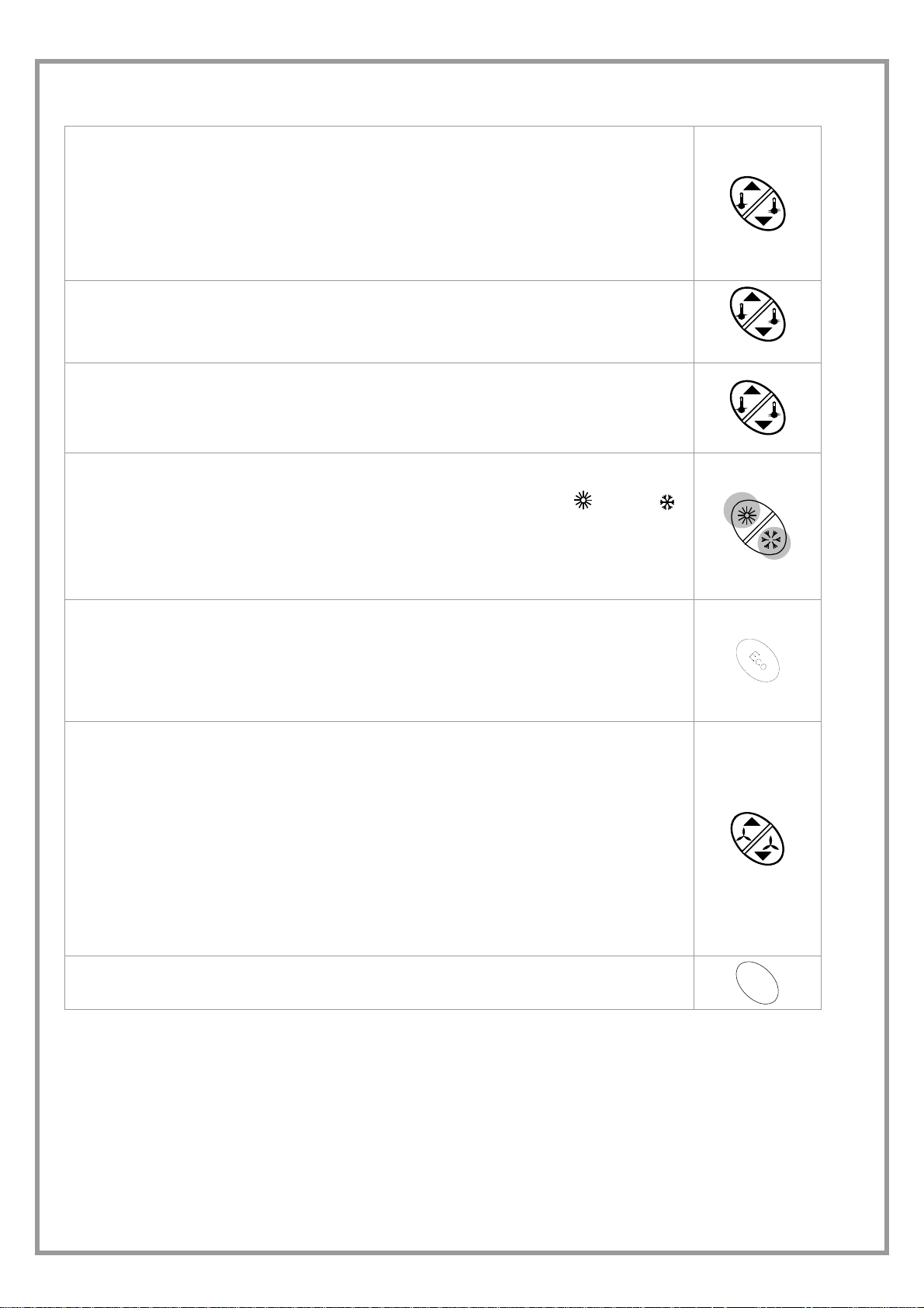
Modify the set-point
Pressing on the arrows raises or lowers set-point of the actual operation (heating, ECO heat.,
cooling ECO cool.).
The difference between the two set-points can not be less than 1°C and this value is automatically
maintained.
If, for example, the unit is in cooling mode and the summer set point is decreased up to the winter
set value, the winter set value is also decreased.
If the function is managed remotely via ModBus, no modification is possible (the word REMOTE
starts flashing)
Display the ambient temperature
Press and hold both arrows of the SET key, and the ambient temperature will be displayed
alternated to the “ t a ” writing.
Display room humidity
ONLY FOR HID-T3 THERMOSTAT WITH UR PROBE
Press and hold both arrows of the SET key, and the ambient temperature will be displayed
alternating with the letters “ta”..
Press and hold the Set key again to see the humidity value alternating with the letters “ur “.
Switch from the HEATING mode to the COOLING mode and vice versa
If the unit is in manual mode, the switch is performed by the relevant key (cooling
; heating )
If “AUTO” is displayed, the switch from one mode to another is managed automatically from the unit
and, if this key is pressed, no change occurs.
If the function is managed remotely via ModBus, no modification is possible (the word REMOTE
starts flashing)
Switch the unit to ECO mode
Press the ECO key
Repeat the operation to restore the standard operation
The ECO summer set point is higher than the SUMMER set point; the ECO winter set point is lower
than the WINTER set point.
If the function is managed remotely via ModBus, no modification is possible (the word REMOTE
starts flashing)
Switch the unit to MANUAL VENTILATION
AUTOMATIC ventilation:
the fan speed is self-adjusted according to ambient temperature
MANUAL ventilation:
speed is increased or decreased by the user.
Pressing one of the two arrow keys, the automatic ventilation is deactivated.
In manual ventilation, the bar corresponding to the active speed is flashing.
To restore the AUTOMATIC ventilation:
Increase to maximum speed
Another pressure of the key will make all 8 bars flash
If no action is performed, the unit returns to automatic ventilation
If the function is managed remotely via ModBus, no modification is possible (the word REMOTE
starts flashing)
Open / close the air supply damper (if present)
HOLD PRESSED
cooling
heating
S
wi
n
g
M42740M4-02 02/10/08 page 21
Page 22

ALARMS VISIBLE BY THE DISPLAY
BEFORE RESETTING AN ALARM, IDENTIFY AND ELIMINATE THE CAUSE OF THE STOP; REPEATED RESETS CAN
CAUSE IRREVERSIBLE DAMAGE.
The ALARMS show a potentially dangerous situation for the unit.
Before resetting an alarm, identify and eliminate the cause of the stop; a repeated reset can cause irreversible damage.
In the event of doubt, ask for an authorized assistance centre.
The table refers to all the variables that are managed by the electronic system.
According to the unit configuration and its accessories, few alarms might not be significant.
RES
FES
BT1
BT2
BT3
H2O
SLF
CO
EHH
SYS
ERR
Active resistance alarm
Active electrostatic filter alarm
Air probe fault alarm
Water probe fault alarm
Fresh air probe fault alarm
Water temperature alarm not fit
Active level sensor alarm
Mode change in progress (for the automatic mode); is not an alarm
Lack of communication/wrong thermostat connection
Fault internal to the control module
Configuration error
PARAMETERS
ACCESS TO PARAMETERS
FOR THE STANDARD USE, THE ACCESS TO PARAMETERS IS NOT NECESSARY.
THE FOLLOWING OPERATIONS ARE NECESSARY FOR CALIBRATIONS AND CONFIGURATIONS, THEY ARE
EXPRESSLY ADDRESSED TO THE AUTHORIZED ASSISTANCE CENTRES OR QUALIFIED TECHNICIANS.
Switch on and off the thermostat with the ON-OFF key and wait until the display
shows the set-point.
Within 5 seconds, press the SWING and ON-OFF keys simultaneously until the P01
code appears
S
wi
n
g
+
in 5 sec
use the “UP” and “DOWN” keys to scroll along the parameters
The value of the parameter to be modified is displayed with the ECO key
Decrease or increase the parameter value
The new parameter value is memorized with the ECO key
S
wi
Simultaneously press the SWING and ON-OFF keys to exit until the set-point appears
n
g
+
M42740M4-02 02/10/08 page 22
Page 23

LIST OF THE PARAMETERS ACCESSIBLE BY THE THERMOSTAT
Par Description range UM Def.
P01 BandaLavoro: Working band
MaxH2Ocool:
P02
Water max. temperature for cooling operating
MinH2OHeat:
P03
Water min. temperature for heating operating
TimeOnPeriodical
P05
Defines the duration of the ON phase of the periodical
TimeOffPeriodical
P06
Defines the duration of the OFF phase of the periodical
P10
OffsetEco
P11 SetUrHeat: Heat UR set point
P12 BandUrHeat: Intervention band of the heat humidifier
FanOffCool:
P21
Fan status at “cooling” thermoregulator, satisfied.
0: stop, 1: continuous , 2: periodical
FanOffHeat:
P22
Fan status at “heating” thermoregulator, satisfied.
0: stop, 1: continuous , 2: periodical
ModoAuto:
P31
It enables the automatic saison change
0: Manual, 1: Auto
0 ÷ 15.0
0 ÷ 30.0
0 ÷ 40.0
0 ÷ 999
0 ÷ 999
0 ÷ 4.0
30 ÷ 70
0 ÷ 10
°C 2.0
°C 20.0
°C 30.0
min 2
min 5
°C 3.0
% 50
% 5
0…2 num 2
0…2 num 0
0…1 flag 0
P41 BT1 probe calibration
P42 BT2 probe calibration
P43 Thermostat temp. probe calibration
P44 Thermostat UR probe calibration
S01 TESToperativa
S02 TH2Ooperativa
S03 TARIAoperativa
S04 URoperativa
S05 Actual mode
S06 CurrentSetpoint
S07 Current humidity Set
S08 Errors
S09 Active humidifcation
S10 Active dehumidification
S11 FanStatus : 0: off, 1: on
-9.9 +10.0 °C 0.0
-9.9 +10.0 °C 0.0
-9.9 +10.0 °C 0.0
-9.9 +10.0 %UR 0.0
°C
°C
°C
Hr%
bitmap
°C
Hr%
bitmap
flag
flag
0…1 flag
Actual fan:
0-7 if motor 0-10 V
S12
0-3 if 3 speed motor
0…7 num
0-1 if single-speed motor
M42740M4-02 02/10/08 page 23
Page 24

HID-TI2 ROOM THERMOSTAT
operating mode selection
S increase the selected field
T decrease the selected field
OK confirm the set datum / thermostat ON – OFF
Ventilation status
Active humidification
Unit in COOLING
Unit in HEATING
Management by ELFO CONTROL
Active compressor
Enabled ECO Setpoint
Unit automatically chooses to cool
or heat
GENERAL DESCRIPTION
The room thermostat HID-TI2/TI3 (hereafter HID) is a device for recessed installation for the remote control of the unit to which
it is connected. It is therefore not a MODBUS network thermostat.
It can be connected to terminal units equipped with terminal.ROOM or terminal.SPACE electronics and makes it possible to
set:
• desired humidity/temperature
• the desired type of ventilation
• a series of advanced functions for the unit to which it is connected
• display any error codes that correspond to alarms sent by the adjustment unit.
• In the HID-TI control there is also a temperature sensor that can be used as a remote sensor for the unit to which it is
connected.
OPERATING MODES
"Normal" operation, HID-TI connected to CLIVET-BUS:
• the HID thermostat shows the operating status of the unit to which it is connected
• periodically measure the temperature/humidity in the room where it is installed
• it is possible to use only the 4 front keys (user programming)
• "Nolink" operation, HID-TI not connected to CLIVET-BUS:
• the thermostat is powered by auxiliary power (a battery must be present)
• it is possible to access hidden keys for installer use
• it is a temporary mode that allows "advanced programming" of the unit.
INITIAL RESET
Insert the battery (auxiliary power supply) and then press the power on key [A] [A].
All display segments will come on for about 3 seconds. Then the display will show the firmware revision of the device.
If the HID device is not connected to CLIVETBUS within one minute, it will go off.
During this time, you can only use the hidden buttons for use by the installer.
You can also use the HID device without a battery. The initial reset is carried out simply upon connection with the CLIVETBUS.
After the initial reset, upon connection to the CLIVETBUS, the device goes into normal operating mode.
USER PROGRAMMING
User programming makes it possible to:
• choose the operating mode of the unit (heating, cooling, eco, fan)
• set the adjustment set point
• manage the fan speed manually or automatically
• enable/disable the floating shutter of the air supply (swing)
• display ambient temperature
• power on/off the adjustment unit
• activate/de-activate silenced mode
POWER ON/OFF
To power on/off the adjustment unit, press and hold the OK key.
Off status is indicated on the display by the message OFF.
M42740M4-02 02/10/08 page 24
Page 25

SELECTION OF MODE OF OPERATION
If you press for about 3 seconds on the key
if you press the key
heating
you can select the desired operating mode in the following cyclical sequence
→
Economical
heating
il the display will show the symbols that define current operating mode.
→
cooling
→
Economical
cooling
→
ventilation
when you press the key [OK] you confirm the displayed mode. The symbols will flash during setting of the mode, and then
normal operation resumes.
During programming of the operating mode, if no key is pressed for about 10 seconds, you will go back to normal operation,
without modifying the operating mode.
MODIFICATION OF ADJUSTMENT SET POINT
In normal operation, for operating modes that include it, you can modify the adjustment set point using the keys [S] e [T]
respectively to increase/decrease in steps of 0.1°.
MANAGEMENT OF FAN SPEED
VENTILATION MODE
in VENTILATION MODE, no adjustments are made to the temperature
you can change fan speed using keys S and T.
MODES: HEATING, ECONOMICAL HEATING, COOLING, AND ECONOMICAL COOLING
press briefly on the key
the bar of the fans
use the keys S and T select the desired speed
go back to normal operation by pressing the key OK
During fan speed modification, if no key is pressed for about 10 seconds, normal operation will resume, preserving any
modifications that have been made.
When setting fan speed, you will go from AUTOMATIC (where the speed of the fans is controlled automatically based on
ambient temperature) to MANUAL operation where the user sets the speed.
To go back to automatic fan operation, repeatedly press S until the entire bar is flashing.
MANUAL STATUS OF THE FANS IS INDICATED BY A FLASHING BAR
The setting of fan speeds is not cyclical.
SILENCED MODE
To activate/de-activate silenced mode briefly press the key OK.
Silenced mode is indicated on the display by the message SIL.
DISPLAY OF AMBIENT TEMPERATURE
You can display the ambient temperature as measured by the probe on the thermostat or the one on the unit. From normal
operating status:
press briefly on key
press key
press the key [OK] to confirm the selection: The message tA will flash on the display, followed by a return to normal operation
in which the message tA will alternate with the ambient temperature for a few seconds.
You can also go back to normal operation by pressing, instead of the key OK the key
without pressing any key.
SWING MODE - CONTROL OF AIR SUPPLY FLOATING SHUTTER
In normal operating status, you can activate/deactivate the Swing function by simultaneously pressing the keys [S] and [T].
There is no indication on the display for the activation/deactivation of this function.
: the display will show the message “Fan” and
: the display will show the message Fan and the bar of the fans.
again: the display will show only the message tA.
or you can wait about 10 seconds
M42740M4-02 02/10/08 page 25
Page 26

BATTERY CHECK
Each time it is powered on, and whenever it is disconnected from the CLIVETBUS, the
device performs a check of the battery charge, which is the source of auxiliary power.
If the battery is nearly dead, the message bAt will appear.
The instrument also works even without an auxiliary power supply. In this case, only the functions related to the front keypad
are accessible.
SIGNALLING OF ALARMS AND MALFUNCTIONS
Any alarms generated by the terminal unit are displayed by the following codes:
RES
FES
BT1
BT2
BT3
H2O
SLF
CO
EHH
SYS
ERR
EUR
The alarm “EHH” is shown about 30 seconds after communication problems between the device and the adjustment unit.
ADVANCED PROGRAMMING
Hidden buttons for use by installer: accessible by extracting the thermostat from its housing.
Active resistance alarm
Active electrostatic filter alarm
Air probe fault alarm
Water probe fault alarm
Fresh air probe fault alarm
Water temperature alarm not fit
Active level sensor alarm
Mode change in progress (for the automatic mode); is not an alarm
Lack of communication/wrong thermostat connection
Fault internal to the control module
Configuration error
Fault humidity probe
bAt
keys accessible only with a tool
R: thermostat reset 8: it hides the dirty filters
A: thermostat starting 9: self-addressing
KEYPAD LOCK
Used to disable functions related to the pressing of user keys.
Take the thermostat out of its housing, and press the key [11]. The display will show the
message bLC
put thermostat back in place
The message bLC will flash until the procedure is complete (a few seconds).
From this moment on, pressing any key will not have any effect, and will instead cause
the display to momentarily show the message bLC.
To go back to a normal situation, release the keypad lock and repeat the operation.
For further details on advanced programming see instructions provided with the room thermostat.
VENTILATION
The system can manage 2 types of ventilation, depending on the type of unit:
ON / OFF
3 speed modes
For any further clarification regarding the type of ventilation refer to the unit electrical diagram.
11
R
A
10
9 8 7 6 5
5, 6: not used
7: reset of the fan fonct. hours
10: access to the configuration parameters
11: keypad lock/unlock
bLC
M42740M4-02 02/10/08 page 26
Page 27

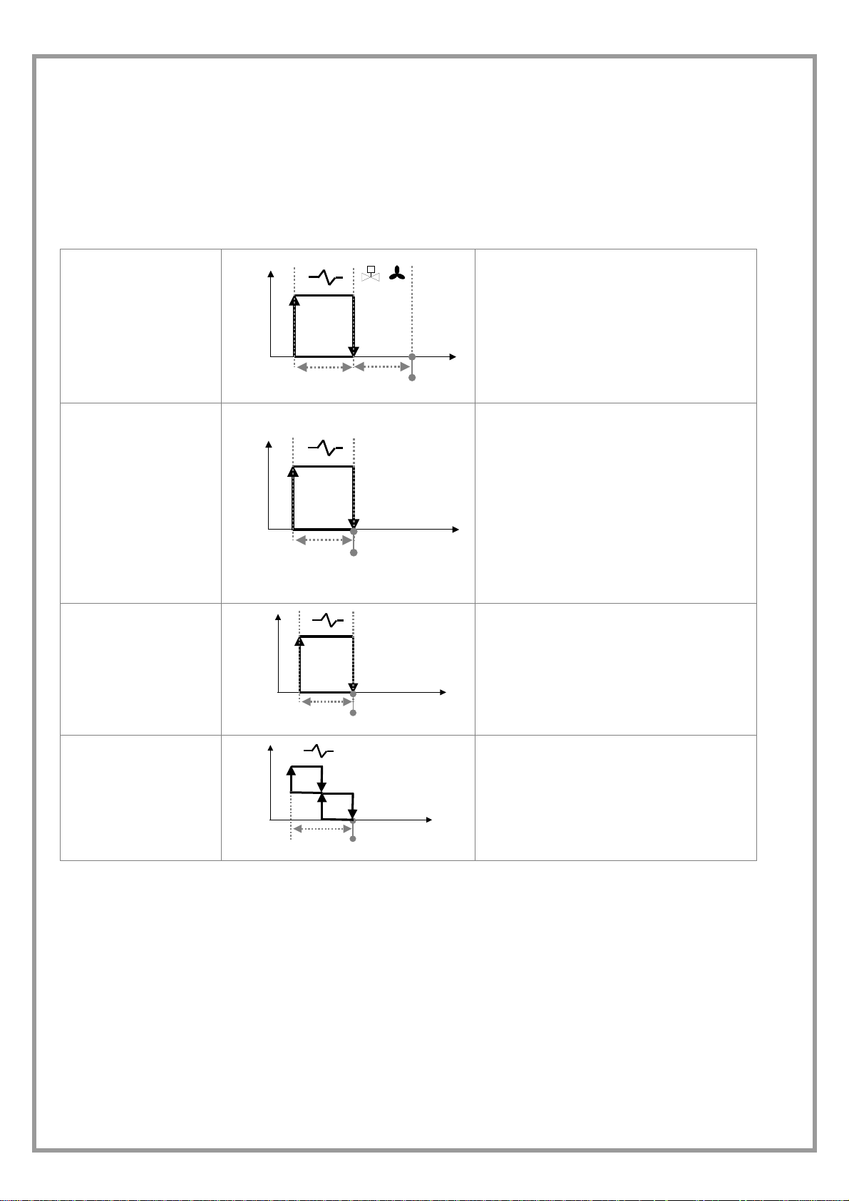
type of ventilation
COOLING HEATING
The ventilation is activated if:
T H2O < P02 Maxh2oCool
If the temperature is out of these limits when
the delay time is finished, the H2O alarm is
activated
T H2O < T ambiente
ON
T H2O > P03 MinH2Oheat
If the temperature is out of these limits when
the delay time is finished, the H2O alarm is
activated
ON
ON / OFF
Sizes 91÷242
OFF
Set-point
1 V
p01 = BandaLavoro
3 V
2 V
T amb. °C
OFF
Set-point
3 V
T amb. °C
p01 = BandaLavoro
2 V
1 V
3 speed
Sizes 31÷71
Set-point
p01 = BandaLavoro
p01 = BandaLavoro
Set-point
WATER VALVE
The system can control 2 ON-OFF valves, one for heat and the other for cold; they are connected to the basic module.
The valve is opened when the thermo-regulator asks for power.
Type of valve COOLING HEATING
%
valve
T amb. °C
0 %
p01 = BandaLavoro
Set-point
0 – 10 v
%
valve
0 %
T amb. °C
p01 = BandaLavoro
Set-point
FRESH AIR DAMPER
By using the proper dedicated output, it is possible to activate a damper or a fan to allow new air to enter the room.
M42740M4-02 02/10/08 page 27
Page 28
ELECTRIC RESISTANCES
The electric resistance operating mode is defined by the following parameters:
P27 ModeRes = 0 integration element (ventilation forced at max.)
1 main element (manual or automatic ventilation)
P53 OutResType = 1 single-phase
2 two-phase
3 0 – 10 volt
ON
INTEGRATION
MAIN ELEMENT
SINGLE-PHASE
RESISTANCES
OFF
ON
OFF
ON
OFF
P01
P01
P01
Set Point
Set Point
P01
Set Point
The water valve is opened when thermoregulation is demanded:
if the probe detects hot water, the resistors
automatically become an integration body.
On the contrary, if after TimeValve is over,
water temperature is not suitable, the valve
closes, the H2O alarm is not activated and the
resistors are not activated.
As soon as the probe detects that water
temperature > MinH2oHeat, resistors become
integration bodies and the valve opens.
In this mode, the water temperature alarm is
not managed.
TWO-PHASE
RESISTANCES
P01
Set Point
DEHUMIDIFICATION
The dehumidification control is managed by the network, which is an upwards system that uses one or more terminal units to
dehumidify.
When the DeumiOn network variable is switched on 1, the unit is forced into cooling mode, even when the temperature set is
met (100% opened valve and minimum ventilation speed).
This occurs to meet the humidity conditions decided by the network (detecting the relevant humidity by a room thermostat).
The dehumidification process shown by the display is stopped when the following occurs:
• the DeumiOn variable is 0 (humidity conditions are met).
• Temperature is below the LowLimit, value; therefore, the process can start again only if ambient temperature > set-point
Temp and if there is still a demand.
The dehumidification process can not start if:
• The operation mode is the Heating mode.
• The unit is OFF.
M42740M4-02 02/10/08 page 28
Page 29

ROUTINE MAINTENANCE
BEFORE UNDERTAKING ANY SORT OF MAINTENANCE OR CLEANING, DISCONNECT THE ELECTRICAL
POWER SUPPLY TO THE UNIT, AND ENSURE THAT OTHER PEOPLE CANNOT RE-CONNECT IT .
All equipment is subjected to wear out.
The maintenance makes :
1. keeps the unit efficiency
2. the components last longer
3. keeps their efficiency and limits breakdowns
Therefore, it is fundamental to perform periodical checks:
a few controls can be performed by the user
(AUTONOMOUS MAINTENANCE) and they are mainly
cleaning activities; otherwise, controls have to be
performed by specialized technicians (INSPECTIONS).
The machine should have a log book used to keep track
of the performed controls. This will make fixing up
breakdowns easier.
Take note of the date, type of control (autonomous
maintenance, inspection or fixing up), description of the
control, actions taken and so on.
SERVICES : parts subject to intervention
• AIR FILTERS
• PLEATED FILTERS
• CONDENSATE DISCHARGE
• ROOM AIR TREATMENT COIL
AIR FILTERS
It is very important for the air treatment coil to be able to offer maximum thermal exchange. Therefore, the unit must always
operate with the filters installed and clean.
Cleaning and replacement of filters are very important in terms of health and hygiene.
Operation with clogged filters leads to a reduction in the air flow rate, resulting in malfunctions and unit shutdowns. It may even
cause the unit to break down.
How often the filters need to be checked depends on the quality of outdoor air, unit operating hours, dust and number of
persons in the rooms.
As a guideline, cleaning should ideally take place between weekly and monthly. It is advisable to start with frequent checks,
and to adjust the frequency based on how much dirt is discovered.
PLEATED FILTERS
1. Remove the closing doors
2. Carefully extract the filter so that no dust reaches
the parts below
3. Wash the filtering mattress in warm water with a
common detergent.
4. Carefully rinse it under water while preventing to
pour water in the room
5. Dry the filter
6. Reinsert it to its seat
7. Reassemble the closing doors
Old filters, washing residuals and residual parts must be
disposed of, according to the law in force.
• STRUCTURE
• DUCTING
• FANS WITH BELT DRIVE
• ELECTRICAL HEATING ELEMENTS
Base unit
Filter inspection panels
1/4 screws
CONDENSATE DISCHARGE
Dust and deposits could cause obstructions.
Clean the tank, pour some water into the tank and check water flows normally.
M42740M4-02 02/10/08 page 29
Page 30

ROOM AIR TREATMENT COIL
ATTENTION: accidental contact with the fins of the exchanger may cause small cuts. When performing the following steps,
use protective gloves.
The finned surfaces of the cooling coils and especially the condensation collection trays are the places where micro-organisms
and moulds most easily flourish. It is therefore very important to clean regularly with suitable detergents and disinfect with
appropriate products as necessary.
STRUCTURE
Check the condition of the parts making up the structure.
Paint so as to eliminate or reduce oxidation at the points in the unit where this problem may occur. Check that the panelling is
fastened correctly. Poor fastening may give rise to malfunctions and abnormal noise and vibration.
DUCTING
Check the fixing screws and the operation of the anti-vibration devices in order to prevent the transmission of vibrations in the room.
FANS WITH BELT DRIVE
BELT
The tension of the belt can be adjusted by the worm screw
on the slide connected to the electric motor, using a
socket wrench or spanner. The belt is tensioned correctly
when the tolerances defined in the enclosed sketch are
respected. The tension of the belt should be checked after
around 10 hours of operation.
Avoid the following situations:
1. Not sufficient tension, which causes slipping and
overheating and, as a consequence, the reduction of
service life.
2. Too much high tension, which subjects the belt to
high stresses and, as a consequence, the reduction
of unit life and an excessive stress on bearings and
PULLEYS
Avoid the following situations:
1. Pulleys not aligned.
2. Pulleys not parallel.
3. dirty pulleys; dust, grease, dirt deposited
between the surfaces of the belt and of the
pulleys can make the system operate in
anomalous conditions.
4. Pulleys not straight.
5. Pulleys too small.
6. Pulleys broken.
7. Pulleys off-centre or unstable.
8. Pulleys worn.
supports.
3. Belt lifted from the groove
4. Belt that reaches the bottom of the groove.
5. Belts of different length (only in the case of coupled
belts).
L = distance between pulleys
F = belt profile force SPA 2,8..3,6 Kg
D = elastic deviation = L x 0,0015
ELECTRIC MOTOR
The cooling air slits must be always free to let the air
pass.
ANTIVIBRATION RUBBERS
BEARINGS
Check regularly if unusual noises are presents.
High size fans are equipped with grease nipples where grease
for bearings must be periodically added.
Periodically check the condition to avoid situations of
anomalous vibrations / noise.
ELECTRICAL HEATING ELEMENTS
The convector finned heating elements need to be checked regularly to ensure that they are clean and properly fastened to the
support.
A
3
(A) STANDARD UNIT
(1) HEATING ELEMENTS
3
2
(2) ELECTRICAL PANEL OF THE RESISTANCE
MANAGEMENT
(3) AIR FLOW DIRECTION
1
M42740M4-02 02/10/08 page 30
Page 31

MAINTENANCE INSPECTIONS
Foresee inspection assistance carried out by authorized
centers or by qualified personnel.
The inspections should be carried out at least:
• Every year for only the cooling units
• Every six months for the cooling and warming
units
The frequency, however, depends on the use: in the event
of frequent use (continuous or very intermittent use, near
the operating limits, etc) or critical use (service necessary)
it is recommended to plan inspections at close intervals.
For units equipped with safety valves, follow the
Manufacturer’s instructions.
Verify periodically the cleaning of the safety valves and
that oxidative / corrosive phenomena are not present, in
particular for installations near the sea, in industrial areas
or in rooms with a corrosive atmosphere.
The inspections to be performed are as follows:
• verify the power supply tension (when emptied or filled)
• inspect the electrical board (status of solenoid starter
contacts, terminal closings, the status of wiring and
relevant insulations)
• inspect the absorption of the single electrical loads
• verify the cleaning and the efficiency of the exchangers
• inspect the cleaning of the filters (air/water)
• verify the leakage from the refrigerating circuit
• Verify the protection devices (safety valves, pressure
switches, thermostats, etc.), the adjustment systems,
the control devices (alarm signalizations, probes,
manometers, etc)
• check the operating parameters of the refrigerating
circuit (see the following REFRIGERANT TABLES and
the START-UP section)
PUT AT REST
If a long period of inactivity is foreseen, for example the
winter for the cooling unit, the following is recommended:
• to turn the power off in order to avoid electrical risks or
damages by lightning strike
• to avoid the risk of frosts as shown in the HYDRAULIC
CONNECTIONS section, and, in particular
- to empty or add glycole in the plant sections
subjected to temperatures below zero
- to empty or add glycole in the water heating coils,
also in summer
- - to power antifreeze resistances if present
If the period of inactivity is particularly long or in the event
of extremely low temperatures, the external fans can be
blocked temporarily; therefore, it is recommended to
switch them on every month in order to avoid seizures or
electrical overloads when the unit will be switched on.
The restarting of the unit has to be carried out by qualified
personnel, in particular, after the winter break for cooling
units or when seasonal switching should be performed.
When restarting, refer to the SWITCHING ON section.
Schedule technical assistance in advance to avoid
hitches and be able to use the installation when
necessary.
M42740M4-02 02/10/08 page 31
Page 32

TROUBLESHOOTING
THE OPERATIONS MUST BE CARRIED OUT BY TECHNICAL QUALIFIED PERSONNEL HAVING THE REQUISITES
UNDER LAW REQUISITES AND IN CONFORMITY WITH THE SAFETY REGULATIONS IN FORCE.
THE INTERVENTIONS WITHIN THE WARRANTY PERIOD WILL BE CARRIED OUT BY AUTHORIZED SERVICE
CENTERS.
BEFORE RESETTING AN ALARM, IDENTIFY AND ELIMINATE ITS CAUSE.
REPEATED RESETS MAY CAUSE SERIOUS DAMAGES.
In certain machine configurations, some safeties may be placed in series and lead back to a single input on the electronic
module.
Therefore, check on the electrical diagram whether the device to which the alarm corresponds has other devices or
safeties connected in series.
DECOMMISSIONING OF THE UNIT
DISCONNECTING THE UNIT
The units must be disconnected by authorised personnel,
who before proceeding must first read the Residual Risks
section in this manual.
Before disconnecting the unit, the following must be
recovered, if present:
• the refrigerant (if the circuits cannot be isolated):
the refrigerant must be removed using suction
devices operating in a closed circuit, so as to
ensure that none of the compound is released into
the atmosphere.
• the antifreeze in the circuits: when removing this
fluid, make sure that it does not leak and that it is
not released into the environment. The antifreeze
fluid must be stored in special containers.
When recovering the substances present in the unit, all
measures must be taken to avoid damaging persons and
things and polluting the surrounding area.
Awaiting dismantling and disposal, the unit can also be
stored outdoors, as bad weather and rapid changes in
temperature will not cause damage to the environment, if
electric, cooling and hydraulic circuits of the unit are integral
and closed.
DISMANTLING AND DISPOSAL
THE UNIT MUST ALWAYS BE SENT TO AUTHORISED
CENTRES FOR DISMANTLING AND DISPOSAL.
When dismantling the unit, the fan, the motor and the coil, if
operating, may be recovered by the specialist centres for
reuse.
All the materials must be recovered or disposed of in
compliance with the corresponding national standards in
force.
For further information on the decommissioning of the unit,
contact the manufacturer
.
M42740M4-02 02/10/08 page 32
Page 33
GENERAL TECHNICAL SPECIFICATIONS
Size 91 121 142 162 182 202 242
COOLING
Cooling capacity 1 kW 29.7 40.3 46.9 52.4 59 75.2 83.8
Sensible capacity 1 kW 22.1 29.7 33.6 38 42.5 52.7 59.5
Total power input 1 kW 0.75 1.1 1.1 1.5 1.5 2.2 3
HEATING
Heat output 2 kW 35.1 47.2 53.2 60.3 76 83.4 94.3
SCAMBIATORE INTERNO
Front surface m2 0.6 0.8 1.02 1.02 1.02 1.43 1.43
Number of rows Nr 4 4 4 4 4 4 4
Fin spacing mm 2.1 2.1 2.1 2.1 1.8 1.8 1.8
Water content l 7 9.4 12.8 12.8 12.8 17.5 17.5
Water flow-rate l/s 1.35 1.84 2.24 2.5 2.8 3.58 4
Pressure drop kPa 20 24 36 43 54 85 104
AIR HANDLING SECTION FANS (OUTLET)
Type of fans 3 CFG CFG CFG CFG CFG CFG CFG
Number of fans Nr 1 1 2 2 2 2 2
Air flow 4 l/s 1417 1889 2120 2500 2660 3100 3620
Installed unit power kW 0.8 1.1 1.1 1.5 1.5 2.2 3
Max outside static pressure 4 Pa 150 150 90 90 60 120 210
Max outside static pressure Pa 240 240 300 300 300 300 300
CONNECTIONS
Water fittings 1"1/4 1"1/4 1"1/4 1"1/4 1"1/4 1"1/4 1"1/4
Condensate discharge 1" 1" 3/4" 3/4" 3/4" 3/4" 3/4"
POWER SUPPLY
Standard power supply V 400/3/50 400/3/50 400/3/50 400/3/50 400/3/50 400/3/50 400/3/50
DIMENSIONS
Length mm 1285 1435 2010 2010 2010 2510 2510
Depth mm 1005 1090 750 750 750 850 850
Height mm 585 685 630 630 630 680 680
STANDARD UNIT WEIGHTS
Shipping weight kg 150 168 190 210 218 280 292
Operating weight kg 138 158 170 190 195 253 265
(1 ) Ambient temperature 27°C/19.5 WB
water inlet 7°C and outlet 12°C
(2) ambient temperature 20°C DB
water inlet 70°C and outlet 60°C
(3) CFG = centrifugal fan
(4) rated flow, maximum speed, including the air filter
OPERATING LIMITS (COOLING)
Size 91 121 142 162 182 202 242
Internal exchanger
Max air temperature inlet (WB) °C 40 40 40 40 40 40 40
Min air inlet temperature (W.B.) °C 2 2 2 2 2 2 2
Max ambient relative humidity % 75 75 75 75 75 75 75
Max water inlet temperature °C 80 80 80 80 80 80 80
Min. water outlet temperature °C 6 6 6 6 6 6 6
OPERATING LIMITS (HEATING)
Size 91 121 142 162 182 202 242
Internal exchanger
Max water inlet temperature
Min. water inlet temperature
Max air temperature inlet (WB)
Min air inlet temperature (W.B.)
DB = dry bulb
WB = wet bulb
°C 80 80 80 80 80 80 80
°C 30 30 30 30 30 30 30
°C 40 40 40 40 40 40 40
°C 2 2 2 2 2 2 2
M42740M4-02 02/10/08 page 33
Page 34

SOUND LEVELS
Size
Sound Power Level (dB)
Octave band (Hz)
63 125 250 500 1000 2000 4000 8000
Sound
pressure
level
dB(A)
91 56 58 54 56 54 49 42 34 43 58
121 56 59 58 59 59 60 57 44 50 65
142 58 60 68 63 61 55 53 49 51 66
162 60 62 69 64 62 56 54 50 52 67
Sound
dB(A)
power
level
The sound levels refer to units ceiling installed
without false ceiling, with nominal air flow, fan
supply 400/3/50, damper on the fan discharge and
1 m. of ducting suction and discharge. Sound
pressure levels referred to 1 m. from units external
surface operating in free field conditions.
182 62 64 69 65 63 57 55 50 52 68
202 63 65 71 65 64 57 55 51 53 68
242 63 66 72 66 63 58 54 51 53 69
EXCHANGER PRESSURE DROP
Operating in cool
DP = PRESSURE DROP
Q = WATER FLOW-RATE
110
100
90
80
70
60
50
P(kPa)
40
30
20
10
0
01234
142-162-182
Q(l/s)
45
40
35
30
25
20
P(kPa)
15
10
5
0
0,0 0,5 1,0 1,5 2,0 2,5
Q(l/s)
202-242
200
150
100
P(kPa)
50
0
0123456
Q(l/s)
Operating in heat
DP = PRESSURE DROP
Q = WATER FLOW-RATE
50
40
30
P(kPa)
20
91
121
91
121
10
0
0,0 0,5 1,0 1,5 2,0 2,5 3,0
Q(l/s)
100
90
80
70
60
50
P(kPa)
40
30
20
10
0
01234
Q(l/s)
142-162-182 202-242
150
100
P(kPa)
50
0
0123456
Q(l/s)
M42740M4-02 02/10/08 page 34
Page 35

Size 91-121
DIMENSIONS
A mm 1285 1435
B mm 945 1030
C mm 585 685
D mm 407 465
E mm 147 176
F mm 270 344
G mm 460 533
H mm 173 210
I mm 7 21
L mm 465 565
M mm 200 250
N mm 1047 1200
O mm 243 280
P mm 435 530
Q mm 987 1074
R mm 1028 1114
S mm 1222 1372
Length mm 1285 1435
Depth mm 945 1030
Height mm 585 685
Size 91 121
(1) CENTRIFUGAL FAN
(2) FAN MOTOR
(3) MAIN WATER COIL
(4) WATER HEATING COIL (OPTIONAL)
(5) PANEL FOR MOTOR AND FAN INSPECTION
(6) PANEL FOR EXCHANGER INSPECTION
(7) EXCHANGER WATER INLET
MAIN WATER COIL
(8) EXCHANGER WATER OUTLET
MAIN WATER COIL
(9) EXCHANGER WATER INLET
ADDITIONAL WATER COIL
(10) EXCHANGER WATER OUTLET
ADDITIONAL WATER COIL
(11) CONDENSATE DISCHARGE
(12) RETURN AIR DIRECTION
(13) SUPPLY AIR DIRECTION
M42740M4-02 02/10/08 page 35
Page 36

Size 142-162-182-202-242
Size 142 162 182 202 242
A mm 2015 2015 2015 2515 2515
B mm 775 775 775 850 850
C mm 630 630 630 680 680
D mm 345 345 345 408 408
E mm 263 263 263 200 200
F mm 571 571 571 735 735
G mm 316 316 316 375 375
H mm 94 94 94 71 71
I mm 52 52 52 38 38
L mm 582 582 582 632 632
M mm 2130 2130 2130 2630 2630
N mm 1720 1720 1720 2220 2220
P mm 442 442 442 492 492
Q mm 642 642 642 742 742
S mm 2070 2070 2070 2570 2570
Length mm 2015 2015 2015 2515 2515
Depth mm 775 775 775 850 850
Height mm 730 730 730 680 680
(1) CENTRIFUGAL FAN
(2) FAN MOTOR
(3) MAIN WATER COIL
(4) WATER HEATING COIL (OPTIONAL)
(5) EXCHANGER WATER OUTLET
MAIN WATER COIL
(6) EXCHANGER WATER INLET
MAIN WATER COIL
(7) EXCHANGER WATER OUTLET
ADDITIONAL WATER COIL
(8) EXCHANGER WATER INLET
ADDITIONAL WATER COIL
(9) POWER INPUT
(10) CONDENSATE DISCHARGE
(11) EASILY REMOVABLE UNIT SUPPORT BASE
(12) RETURN AIR DIRECTION
(13) SUPPLY AIR DIRECTION
M42740M4-02 02/10/08 page 36
Page 37

M42740M4-02 02/10/08 page 37
Page 38

Page 39

Page 40

CLIVET SPA
Feltre (BL) ITALY
Tel. + 39 0439 3131
Fax + 39 0439 313300
info@clivet.it
CLIVET ES PAÑA S.A.
Madrid - SPAIN
Tel. + 34 91 6658280
Fax + 34 91 6657806
info@clivet.es
CLIVET UK LTD
Fareham (Hampshire) U.K.
Tel. + 44 (0) 1489 572238
Fax + 44 (0) 1489 573033
info@cli vet-uk.co.uk
CLIVET NEDERLAND B.V.
Amersfoort - Netherlands
Tel. + 31 (0) 33 7503420
Fax + 31 (0) 33 7503424
info@clivet.nl
CLIVET SPA
BUREAU DE LIAISON EN FRANCE
Verrierès le Buisson - FRANCE
Tel. + 33 (0)1 69 20 25 75
Fax + 33 (0)1 69 20 60 76
info.fr@clivet.com
CLIVET GmbH
Norderstedt - GERMANY
Tel. +49 (0) 40 32 59 57-0
Fax +49 (0) 40 32 59 57-194
info.de@clivet.com
CLIVET TFAIR SYSTEMS (P)LTD.
Malur - INDIA
Tel. +91 8151 232683/5
Fax +91-8151-232684
info@cli vettfa.com
The data contained in this bulletin is not binding and may be changed by the manufacturer without prior notice. All reproduction, even
partial, is PROHIBITED.
© COPYRIGHT - CLIVET S.P.A. - FELTRE (BL) - ITALIA
 Loading...