

CLIVET AQUA SWAN 190, AQUA SWAN 190S, AQUA SWAN 300, AQUA SWAN 300S Installation And Operating Manual
INSTALLATION AND
OPERATING MANUAL
AQUA SWAN 190-300
Heat pumps for domentic hot water
M0MR40E17-00
15-11-2017

Dear Customer,
We congratulate you on choosing this product
For many years Clivet has been offering systems that provide maximum
comfort, together with high reliability, efficiency, quality and safety.
The aim of the company is to offer advanced systems, that assure the best
comfort, reduce energy consumption and the installation and maintenance
cost for the life cycle of the system.
The purpose of this manual is to provide you with information that is useful
from reception of the equipment, through installation, operational usage and
finally disposal so that this advanced system offers the beat solution.
Yours faithfully.
CLIVET Spa
INDEX
Before any operation carefully read the GENERAL WARNINGS
1 General instructions
2 Residual risks / Disposal
3 General
4 Reception
5 Installation
6 Water connections
7 Aeraulic connections
8 Electrical connections
4
8
11
14
16
18
22
25
9 Start - up
10 Control
11 Maintenance
12 Technical data
Pay particular attention to:
INSTALLER use
USER use
WARNING, identifies particularly important operations or information
PROHIBITIONS, identifies operations that must not be carried out, that compromises the
operating of the unit or may cause damages to persons or things.
29
35
46
51
The data contained in this manual is not binding and may be modified by the manufacturer without prior notice. preliminary
3

1 - GENERAL INSTRUCTIONS
USER
This appliance can be used by children
aged from 8 years and above and
persons with reduced physical, sensory
or mental capabilities or lack of
experience and knowledge if they have
been given supervision or instruction
concerning use of the appliance in a
safe way and understand the hazards
involved. Children shall not play with the
appliance. Cleaning and user
maintenance shall not be made by
children without supervision.
Before cleaning, be sure to stop the
operation and turn the breaker off or pull
out the power plug.
Otherwise, an electric shock and injury
may be caused.
Do not insert fingers, rods or other
objects into the air inlet or outlet.
When the fan is rotating at high speed, it
will cause injury.
Do not touch the inner parts of the
controller.
Do not remove the front panel.
Some parts inside are dangerous to
touch, otherwise a machine malfunction
may be caused.
Never use a flammable spray such as
hair spray, lacquer paint near the unit, it
may cause a fire.
Do not remove, cover or deface any
permanent instructions, lables, or the
data label from either the outside of the
unit or inside of unit panels.
It is forbidden the use of the device to
children and unassisted disables .
It is forbidden to touch the device if you
are barefoot and with wet body parts .
It is forbidden any cleaning, before
having disconnected the device
positioning the system main switch on
“off”.
It is forbidden to pull, remove, twist the
electric cables that come out from the
device even if it is disconnected from the
mains supply.
It is forbidden to trample on the device
and/or to put on it any type of object.
It is forbidden to throw or spray water
directly on the device.
It is forbidden to insert sharpened
objects by the air return and supply
grilles.
It is vorbidden to open the lids of access
to the internal device parts, without
having before positioned the main switch
of the system on “off”.
Do not turn off the power supply.
If the supply cord is damaged, it must be
replaced by the manufacturer or its
service agent or a similarly qualified
person.
The wiring must be performed by
professional technicians in accordance
with national wiring regulations.
A disconnect device for all poles having
a separation distance of at least 3 mm
across all poles and that a residual
current device (RCD) with a power
greater than 10mA is incorporated into
fixed wiring.
System will stop or restart heating
automatically.
A continuous power supply for water
heating is necessary, except service and
maintenance.
Keep this manual with the wiring
diagram in an accessible place for the
operator.
Children should be supervised to ensure
that they do not play with the unit.
Note the unit lable data so you can
provide them at the assistance centre in
case of intervention (see "Unit
identification" section)
Provide a unit notebook that allows any
interventions carried out on the unit to
be noted and tracked making it easier to
suitably note the various interventions
and aids the search for any breakdowns.
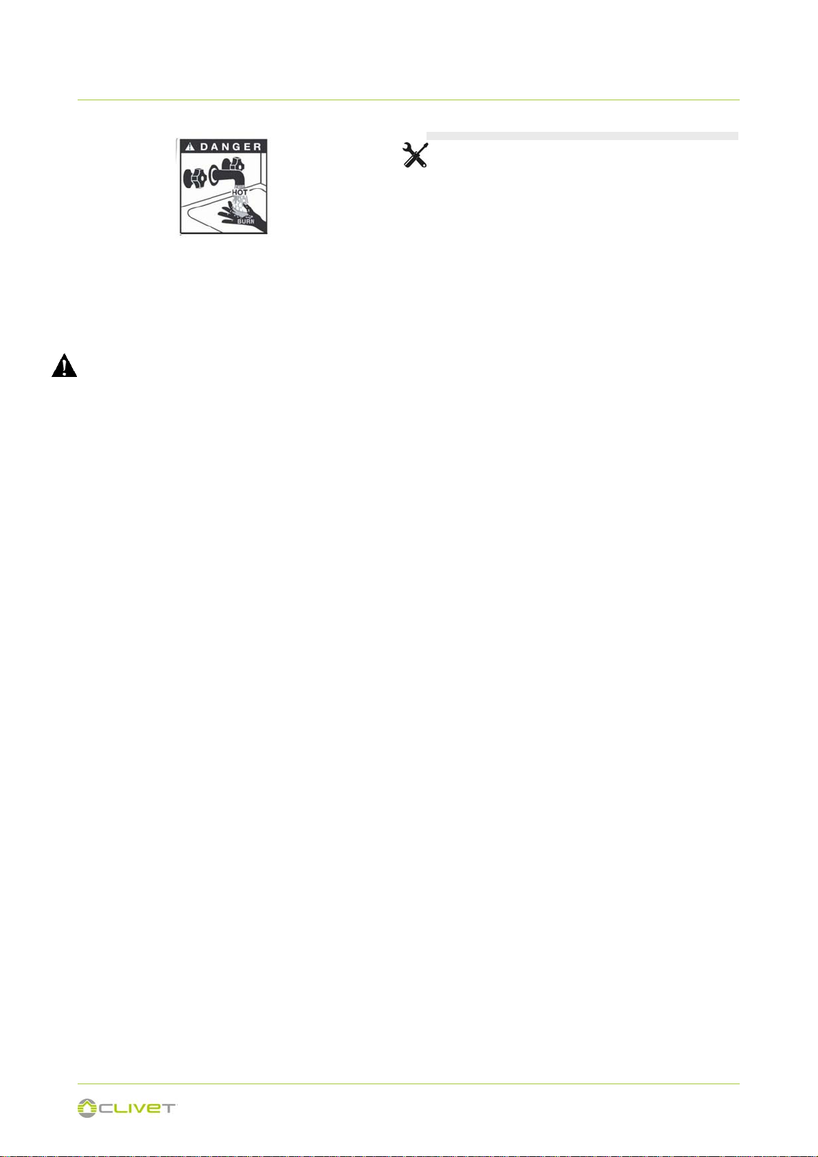
Water temperature over 50°C can cause
severe burns instantly or death from
scalds.
4
1 - GENERAL INSTRUCTIONS
Children, disabled and elderly are at
highest risk of being scalded.
Feel water before bathing or showering.
Water temperature limiting valves are
recommended.
If the unit has not been used for a long
period of time(2 weeks or more),
hydrogen gas will be produced in the
water piping system.
Hydrogen gas is extremely flammable.
To reduce the risk of injury under these
conditions, it is recommended that open
the hot water tap for several minutes at
the kitchen sink before using any
electrical appliance connected to the hot
water system. When hydrogen is
present, there will probably be an
unusual sound such as air escaping
through the pipe as the water begins to
flow.
There should be no smoking or open
flame near the tap at the time it is open.
Ask qualified person for relocating,
repairing and maintaining the unit
instead of doing by yourself.
In case of breakdown or malfunction:
- immediately deactivate the unit
- Contact a constructor certified
assistance service.
- Use original spares parts only
Ask the installer to be trained on:
- start-up / shutdown
- set points change
- standby mode
- maintenance
- what to do / what not to do in case
of breakdown
GENERAL INSTRUCTIONS
Preliminaries
Read carefully the IOM and use the unit
strictly according to the instructions in
order to avoid personal injuries, damages
to the unit, damages to property and
litigations.
Our company does not assume any legal
liability for any damage caused by
improper use of the unit.
The positioning, hydraulic system,
refrigerating, electrics and the air duct
must be determined by the system
designer or by experts and must take into
consideration both the decidedly
technical requirements as well as any
local regulations in act regarding specific
authorisations.
Only qualified personnel can operate on
the unit, as required by the regulation in
force.
Using the unit in case of breakdown or
malfunction :
voids the warranty
may compromise the safety of the
unit
may increase time and repair costs.
Follow local safety regulations.
Keep packing material out of children’s
reach it may be dangerous.
Recycle and dispose of packing material
in conformity with local regulations.
Risk situations
The unit has been designed and created
to prevent injures to people. During
designing it is not possible to plane and
operate on all risk situation. Read
carefully "Residual risk" section where all
situation which may cause damages to
things and injuries to people are
reported. Installation, starting,
maintenance and repair required specific
knowledge; if they are carried out by
inexperienced personnel, they may
cause damages to things and injuries
people.
Intended use
Use the unit for cooling/heating air only
5

1 - GENERAL INSTRUCTIONS
and domestic hot water, within limits
defined in the technical bulletin and on
this manual.
Any use other than intended does not
involve the manufacturer in any
commitment or obligation.
HYDRAULIC SYSTEM
Components
Selection and installation of system
components must be carry out by
installer.
Water quality
The water quality is determined by the
following factors, avoid therefore:
- Inorganic salts
- pH
- Biological load (seaweeds etc)
- Suspended solids
- Dissolved oxygen
Water with inadequate characteristics
can cause:
- pressure drop increase
- energy efficiency decrease
- corrosive symptom increase
Risk of freeze
If the unit or the relative water
connections can be subject to
temperatures close to 0°C adopt
measures for prevent risk of freeze.
The appliance is intended to be
permanently connected to the water
mains and not connected by a hose-set .
The water may drip from the discharge
pipe of the pressure-relief device and
that this pipe must be left open to the
atmosphere.
The pressure-relief device is to be
operated regularly to remove lime
deposits and to verify that is not blocked.
A discharge pipe connected to the
pressure-relief device is to be installed in
a continuously downward direction and
in a frost-free environment.
ELETTRIC SYSTEM
This unit is required reliable earthing
before usage, otherwise might cause
death or injury.
General
The characteristics of the electrical lines
must be determined by specialized
personnel able to design electrical
installations; moreover, the lines must be
in conformity with regulations in force.
Operate in compliance with safety
regulations in force .
This unit is required reliable earthing
before usage, otherwise might cause
death or injury.
If you can't make sure that your house
power supply is earthed well, please
don't install the unit if it does not in
conformity with regulations in force.
The power supply should be an
independent circuit with rated voltage.
Power supply circuit should be earthed
effectively.
Do not use water pipes to earthing
connection of the unit
Use single protection devices : gloves,
glasses ecc.
The power cables and the protection
cable section must be defined in
accordance with the characteristics of the
protections adopted. The serial number
label reports the unit specific electrical
data, included any electrical accessories.
Connection
All electrical operations should be
performed by trained personnel having
the necessary requirements by the
regulations in force and being informed
about the risks relevant to these
activities. Refer to the unit electrical
diagram (the number of the diagram is
6
1 - GENERAL INSTRUCTIONS
shown on the serial number label). Verify
that the network has characteristics
conforming to the data shown on the
serial number label .
Make sure that the unit supply line is
selected at start.
Shelter the cables using adequate
measure fairleads.
Before starting work, verify that the
sectioning device at the start of the unit
power line is open, blocked and equipped
with sign warning.
First create the earthing connection.
After wire connection, check it again and
make sure the correctness before power
on.
Prior to powering the unit ensure that all
the protections that were removed during
the electrical connection work have been
restored.
Signal lines/data-lay
Do not overpass the maximum power
allowed, which varies, according to the
type of signal.
Lay the cables far from power cables or
cables having a different voltage and that
are able to emit electromagnetic
disturbances. Do not lay the cable near
devices which can generate
electromagnetic interferences.
Do not lay the cables parallel to other
cables; cable crossings are possible, only
if laid at 90°.
Connect the screen to the ground, only if
there aren’t disturbances .
Guarantee the continuity of the screen for
the entire extension of the cable.
Respect impendency, capacity and
attenuation indications.
MODIFICATION
All unit modifications will end the
warranty coverage and the manufacturer
responsibility.
BREAKDOWN/MALFUCTION
Disable the unit immediately in case of
breakdown or malfunction.
Contact a constructor certified assistance
service.
Use original spares parts only.
USER TRAINING
The installer has to train the user on :
- ON / OFF
- set points change;
- standby mode;
- Maintenance;
- what to do / what not to do in case of breakdown.
DATA UPDATE
Continual product improvements may
imply manual data changes
Visit manufacturer web site for updated
data.
7

2 - RESIDUAL RISKS / DISPOSAL
RESIDUAL RISKS
General
In this section the most common
situations are signalled. As these cannot
be controlled by the manufacturer these
could be a source of risk situations for
people or things.
Danger zone
This is an area in which only an
authorised operator may work. The
danger zone is the area inside the unit
which is accessible only with the
deliberate removal of protections or parts
thereof.
Handling
The handling operations, if implemented
without all of the protection necesssary
and without due caution, may cause the
fall or the tipping of the unit with the
consequent damage, even serious, to
persons, things or the unit itself. Handle
the unit following the instructions
provided in the present manual regarding
the packaging and in compliance with the
local regulations in force.
Should the gas refrigerant leak please
refer to the refrigerant "Safety sheet".
Installation
An incorrect installation of the unit could
cause water leaks, condensate
accumulation, leaking of the refrigerant,
electric shock, bad functioning or
damage to the unit itself.
Check that the installation has been
implemented by qualified technical
personnel only and that the instructions
contained in the present manual and the
local regulations in force have been
adhered to. The installation of the unit in
a place where even infrequent leaks of
inflammable gas and the accumulation of
this gas in the area surrounding the area
occur could cause explosions or fires.
Carefully check the positioning of the
unit. The installation of the unit in a place
unsuited to support its weight and/or
guarantee adequate anchorage may
cause the fall or the tipping of the unit
with the consequent damage to things,
people or the unit itself. Carefully check
the positioning and the anchoring of the
unit.
Easy access to the unit by children,
unauthorised persons or animals may be
the source of accidents, some serious.
Install the unit in areas which are only
accessible to authorised person and/or
provide protection against intrusion into
the danger zone .
General risks
Smell of burning, smoke or other signals
of serious anomalies may indicate a
situation which could cause damage to
people, things or the unit itself.
Electrically isolate the unit (yellow-red
isolator).
Contact the authorised service centre to
identify and resolve the problem at the
source of the anomaly.
Accidental contact with exchange
batteries, compressors, air delivery pipes
or other components may cause injuries
and/or burns. Always wear suitable
clothing including protective gloves to
work inside the danger zone.
Maintenance and repair operations
carried out by non-qualified personnel
may cause damage to persons, things or
the unit itself.
Always contact the qualified assistance
centre.
Failing to close the unit panels or failure
to check the correct tightening of all of
the panelling fixing screws may cause
damage to persons, things or the unit
itself. Periodically check that all of the
panels are correctly closed and fixed. If
there is a fire the temperature of the
8

2 - RESIDUAL RISKS / DISPOSAL
refrigerant could reach values that
increase the pressure to beyond the
safety valve with the consequent possible
projection of the refrigerant itself or
explosion of the circuit parts that remain
isolated by the closure of the tap. Do not
remain in the proximity of the safety valve
and never leave the refrigerating system
taps closed.
Electric parts
An incomplete attachment line to the
electric network or with incorrectly sized
cables and/or unsuitable protective
devices can cause electric shocks,
intoxication, damage to the unit or fires.
Carry out all of the work on the electric
system referring to the electric layout and
the present manual ensuring the use of a
system thereto dedicated. An incorrect
fixing of the electric components cover
may favour the entry of dust, water etc
inside and may consequently can electric
shocks, damage to the unit or fires.
Always fix the unit cover properly. When
the metallic mass of the unit is under
voltage and is not correctly connected to
the earthing system it may be as source
of electric shock and electrocution.
Always pay particular attention to the
implementation of the earthing system
connections. Contact with parts under
voltage accessible inside the unit after
the removal of the guards can cause
electric shocks, burns and electrocution.
Open and padlock the general isolator
prior to removing the guards and signal
work in progress with the appropriate
shield.
Contact with parts that could be under
voltage due to the start up of the unit may
cause electric shocks, burns and
electrocution.
When voltage is necessary for the circuit
open the isolator on the attachment line
of the unit itself, padlock it and display
the appropriate warning shield.
Moving parts
Contact with the transmissions or with
the fan aspiration can cause injuries.
Prior to entering the inside of the unit
open the isolater situated on the
connection line of the unit itself, padlock
and display the suitable sign.
Contact with the fans can cause incurie.
to removing the protective grill or the
fans, open the isolator on the attachment
line of the unit itself, padlock it and
display the appropriate warning sign.
Refrigerant
The intervention of the safety valve and
the consequent expulsion of the gas
refrigerant may cause injuries and
intoxication. Always wear suitable
clothing including protective gloves and
eyeglasses for operations inside the
danger zone.
Should the gas refrigerant leak please
refer to the refrigerant "Safety sheet".
Contact between open flames or heat
sources with the refrigerant or the
heating of the gas circuit under pressure
(e.g. during welding operations) may
cause explosions or fires.
Do not place any heat source inside the
danger zone.
The maintenance or repair interventions
which include welding must be carried
out with the system off.
Hydraulic parts
Defects in ducting , the attachments or
the cut-off parts may cause a leak or
water projection with the consequent
damages to people, things or shortcircuit
the unit.
9
2 - RESIDUAL RISKS / DISPOSAL
DISCONNECTION
Only authorised personnel must
disconnect the unit.
Avoid leak or spills into the environment.
Before disconnecting the unit, the
following must be recovered, if present:
- refrigerant gas
When awaiting dismantling and disposal,
the unit can also be stored outdoors, as
bad weather and rapid changes in
temperature will not cause damage to the
environment, if the unit's electric, cooling
and hydraulic circuits are integral and
closed.
DISPOSAL
CE WEEE DIRECTIVE
The units covered by the legislation in
question are marked with the symbol on
the side.
With the aim of protecting the
environment, all of our units are
produced in compliance with CE
Directive on waste electrical and
electronic equipment (WEEE).
The potential effects on the environment
and on human health due to the
CE-WEEE directive requires disposal
and recycling of electrical and electronic
equipment as described therein to be
handled through appropriate collection, in
suitable centres, separate from collection
for the disposal of mixed urban waste.
The user must not dispose of the unit at
the end of its life cycle as urban waste. It
must instead be handed over to
appropriate collection centres as set forth
by current standards or as instructed by
the distributor.
If disposal takes places at the same time
as delivery of a new electrical or
electronic equipment for the same family,
the product may be collected directly by
the distributor.
Dismantling and disposal
THE UNIT MUST ALWAYS BE SENT TO
AUTHORISED CENTRES FOR
DISMANTLING AND DISPOSAL.
When dismantling the unit, the fan, the
motor and the coil, if operating, may be
recovered by the specialist centres for
reuse. All the materials must be
presence of hazardous substances are
shown in the use and maintenance
manual in the section on residual risks.
Information in addition to that indicated
below, if required, can be obtained from
the manufacturer/distributor/importer,
who are responsible for the collection/
handling of waste originating from
equipment covered by CE-WEEE. This
information is also available from the
retailer who sold this appliance or from
the local authorities who handle waste.
10
3 - GENERAL
UNIT INDENTIFICATION
Serial number label
The serial number label is positioned on the unit and allows to
indentify all the unit features.
It has not to be removed for any reason.
It reports the regulations indications such as:
machine type, exmple:
Series SWAN
Size 190-190S-300-300S
serial number
12 characters Axxxxxxxxxxx
year of manufacture
wiring diagram number
electrical data
manufacturer logo and address .
Serial number
It identifies uniquely each machine.
It identifies specific spare parts for the machine.
Assistance request
Note data from the serial number label and write them in the
chart on side, so you will find them easily when needed.
In case of intervention you have to provide data.
Serie
Size
Serial number
Year of manufacture
Wiring diagram
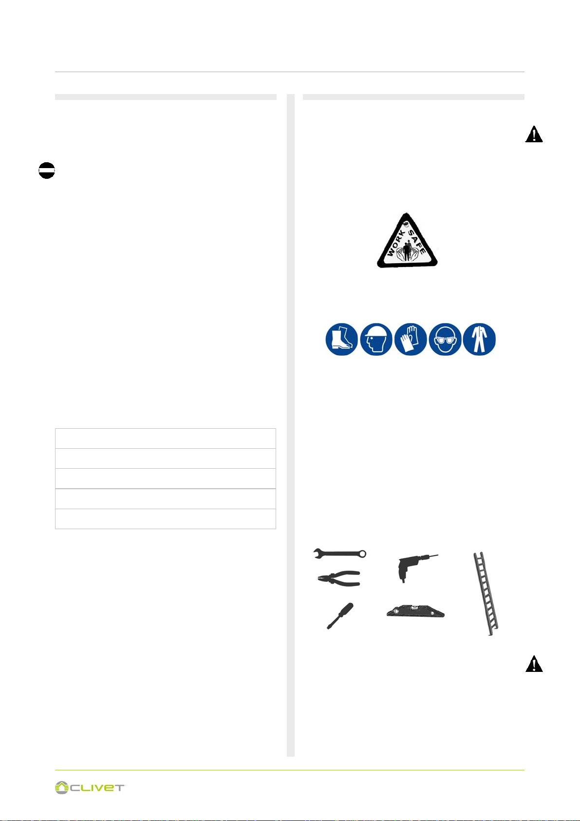
PRELIMINARY INFORMATION
Before beginning the work, ensure you that have the final
project for installing the aeraulic, hydraulic, electric,drains and
positioning the units.
Operate in compliance with safety regulations in force .
Use single protection devices.
Recommended instruments
Set of Philips and flathead screwdrivers;
Cutters;
Drill;
Scissors;
Set of open spanners or pipe wrenches;
Range;
Hydraulic material for the sealing of the threads;
Electrical equipment for the connections;
Cut prevention gloves;
Tester and amperometric pliers.
BEFORE REQUESTING START-UP
Completed aeraulic system and free of dirt
Completed water system, circuit loading and venting
Discharges unit connected
Electric connections
11
3 - GENERAL
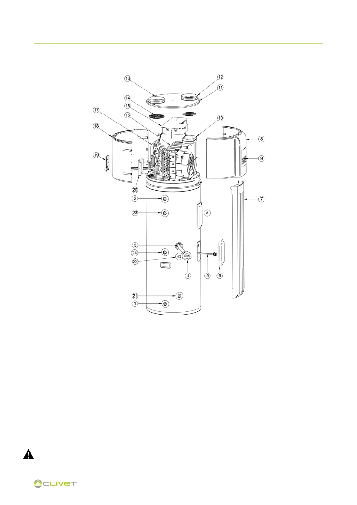
PARTS NAMES - 190 LITRES
1) Water inlet 3/4” F
2) Domestic hot water outlet 3/4” F (ACS)
3) Sacrificial anode
4) Anode cap
5) Electric heater
6) Heating element cap
7) Front mask
8) Front cover
9) Unit control keypad
10) Fan
11) Top cover
12) Air outlet flange
13) Air inlet flange
When ordering repair parts please always give the following information:
Model, serial and product number.
Parts name.
All the picture in this manual are for explanation purpose only. They may be slightly different from the unit you purchased (depand on
model). Please refer to the real sample instead of the picture of this manual.
14) Air filter
15) Electric panel
16) Evaporator
17) Compressor
18) Rear closure
19) Electrical connector cover
20) Electrical connections box
21) Solar inlet 3/4” F (Solar version only)
22) Solar outlet 3/4” F (Solar version only)
23) DHW recirculation (Solar version only)
24) Probe sump for solar
A - ATCO (automatic temperature Switch)
TCO (temperature Switch)
12
3 - GENERAL
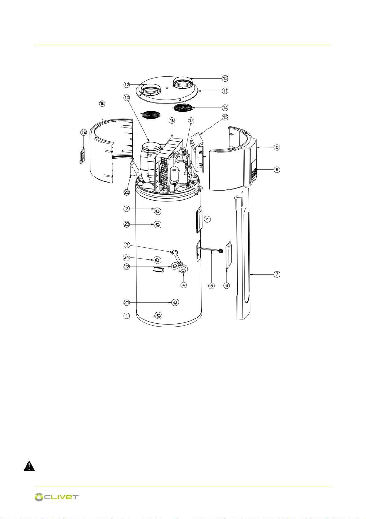
PARTS NAMES - 300 LITRES
1) Water inlet 3/4” F
2) Domestic hot water outlet 3/4” F (ACS)
3) Sacrificial anode
4) Anode cap
5) Electric heater
6) Heating element cap
7) Front mask
8) Front cover
9) Unit control keypad
10) Fan
11) Top cover
12) Air outlet flange
13) Air inlet flange
When ordering repair parts please always give the following information:
Model, serial and product number.
Parts name.
All the picture in this manual are for explanation purpose only. They may be slightly different from the unit you purchased (depand on
model). Please refer to the real sample instead of the picture of this manual.
14) Air filter
15) Electric panel
16) Evaporator
17) Compressor
18) Rear closure
19) Electrical connector cover
20) Electrical connections box
21) Solar inlet 3/4” F (Solar version only)
22) Solar outlet 3/4” F (Solar version only)
23) DHW recirculation (Solar version only)
24) Probe sump for solar
A - ATCO (automatic temperature Switch)
TCO (temperature Switch)
13
4 - RECEPTION
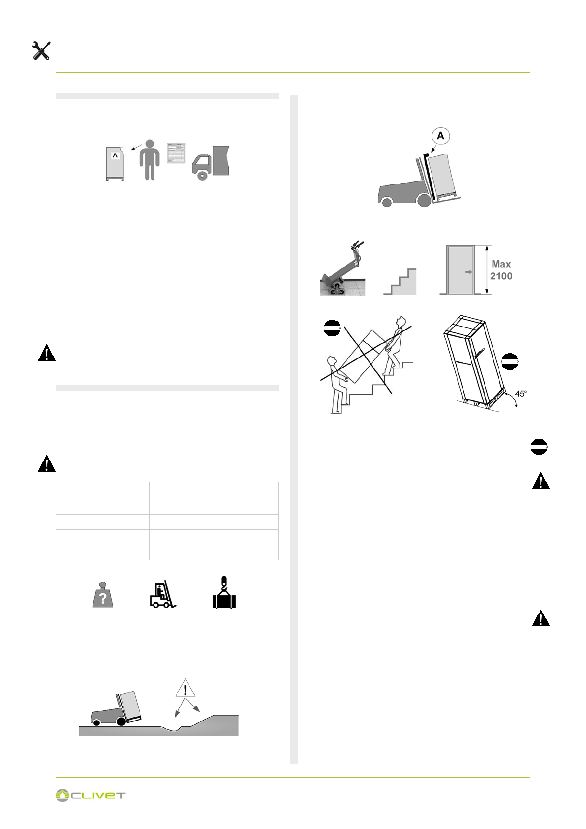
4.1 - DELIVERY CONTROL
Before accepting the delivery you have to check:
that the unit hasn’t been damaged during transport.
Check that the materials delivered correspond with that
indicated on the transport document comparing the data
with the identification label ‘A’ positioned on the packa-
ging.
In case of damage or anomaly:
Write down on the transport document the damage you
found and quote this sentence: "Conditional acceptance
clear evidence of deficiencies/damages during transport".
Contact supplier and the carrier by fax and registered mail
with advice of receipt.
Any disputes must be made within the 8 days following the
delivery. Complaints after this period are invalid.
Use protection (A) to avoid the unit damaging
Stair climbing trolley.
4.2 - HANDLING
The following examples are indications the choice of the
means and of the handling modes will depend on factors.
Verify the lifting equipment's load-bearing capacity: the shipped unit weighs
Unit
190 litres kg 126
190 litres (with solar) kg 149
300 litres kg 149
300 litres (with solar) kg 171
Identify critical points during handling (disconnected routes,
flights, steps, doors).
Shipping weight
Maximum inclination
When transporting the unit, do not carry it by holding on to the
top part of the circuit.
This unit is heavy, it need to be carried by two or more persons, otherwise might cause injury and damage.
In order to avoid scratch or deformation of the unit surface,
apply guard boards to the contacting surface.
No contact of fingers and other things with the vanes.
While moving it, do not tip the unit to an angle less than 45°
and keep it in a vertical position during installation.
If the unit has been tipped during transport, wait at least 2
hours before starting it up
14

4 - RECEPTION
4.3 - PACKAGING REMOVING
Be careful not to damage the unit.
Keep packing material out of children’s reach it may be dangerous.
Recycle and dispose of the packaging material in conformity
with local regulations.
Cut the hoops
1
Front
Cut along the joint (A)
2
Rear
3
A
15
5 - POSITIONING
5.1 - INSTALLATION REQUIREMENTS
The installation has been implemented by qualified technical
personnel only and that the instructions contained in the
present manual and the local regulations in force have been
adhered to.
Choose the installation place according to the following
criteria:
customer approval
Internal
in a dry room/compartment where the temperature cannot
fall below 0 degrees
guarantee good unit operation
safe accessible position
enough space for installation and maintenance shall be
preserved.
the air inlet and outlet should be free from obstacles and
strong wind.
the base surface should be flat, surface should be inclined
no more than 2°and able to bear the weight of the unit and
suitable for installing the unit without increasing noise or
vibration.
the operation noise and air flow expelled shall not affect
neighbors.
If the unit has to be installed on a metal part of building,
make sure the well electric insulation which should meet
the relevant local electric standard.
use of air from heated rooms could penalise the heating
performance of the building
The unit must be securely fixed, elsewise, noise and
shaking may be resulted.
Make sure that there’s no obstacle around the unit.
The external air temperature must also be considered when
installing this unit, in heat pump mode the external air
temperature must be above -7°C and below 43°CIf the
externalair temperature falls outside these upper and lower
limits, the electrical elements will activated to meet the hot
water demand and the heat pump does not operate.
The unit should be located in an area not subject to freezing
temperatures. The unit located in unconditioned spaces(i.e.,
garages, basements, etc.) may require the water piping,
condensate piping, and drain piping to be insulated to shelter
against freezing.
Installing the unit in any of the following places may lead to
malfunction:
The site contains mineral oils such as cutting lubricant
Seaside where the air contains much salt.
Hot spring area where corrosive gases exist, e.g., sulfide
gas.
Factories where the power voltage fluctuates seriously.
Inside a car or cabin.
The place with direct sunlight and other heat supplies. If
there’s no way to avoid these, please install a covering.
Place like kitchen where oil permeates.
Place where strong electromagnetic waves exist.
Place where flammable gases or materials exist.
Place where acid or alkali gases evaporate.
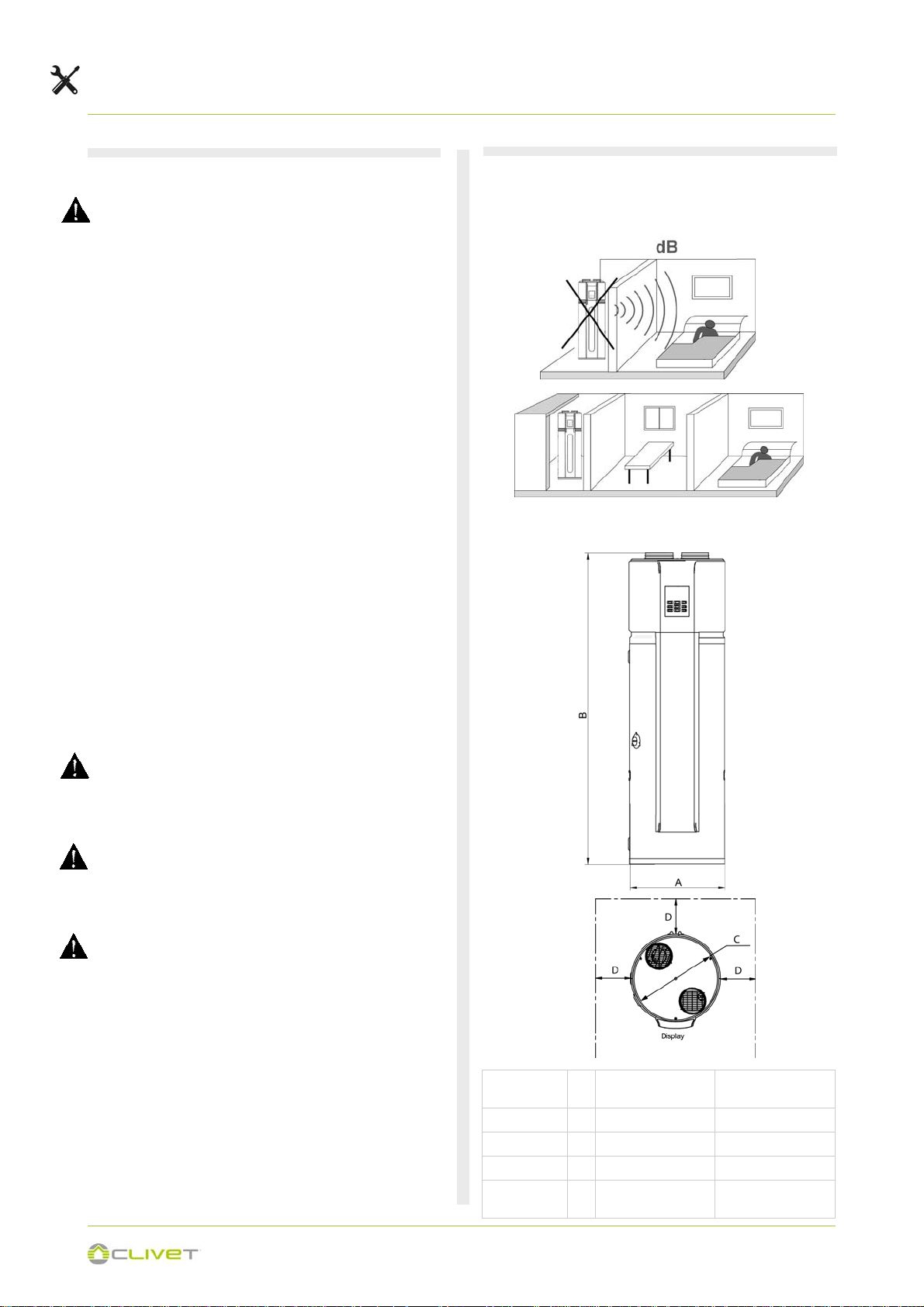
5.2 - CONSIDER SOUND EMISSIONS
Noise levels could represent an inconvenience if installed in
areas that require extreme silence, exsample near bedrooms.
Unit dimension / Functional spaces
Unit 190L
Width A 560 650
Height B 1830 1930
Diameter C 560 650
Functional
spaces
190L (with solar)
D = 600 = 600
300L
300L (with solar)
16
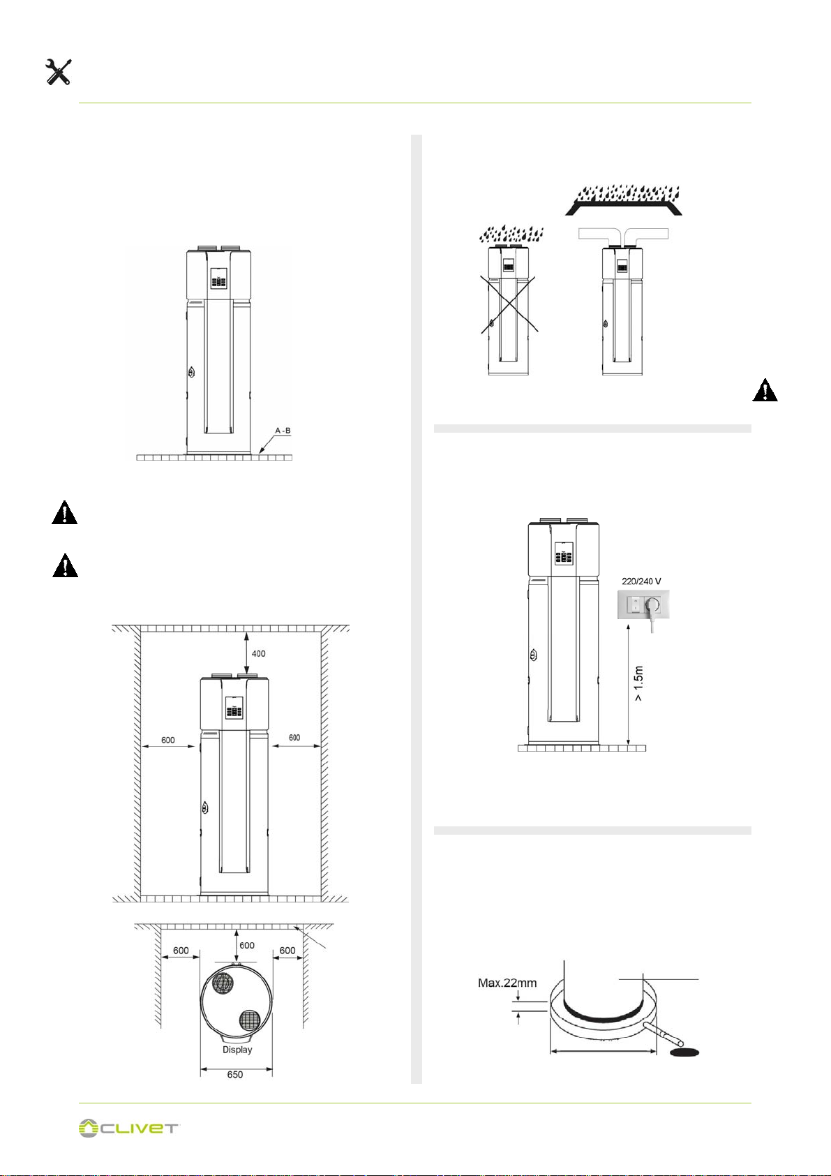
5 - POSITIONING
Check that the floor can support the weight of the unit in
operation:
A - > 287 Kg/m
> 310 Kg/m
B - > 412 Kg/m
> 435 Kg/m
2
(190L)
2
(190S with solar)
2
(300L)
2
(300S with solar)
If installed in inclosed space
The unit must be located in a space >15m³, and must have
unrestricted air flow.
Make sure there is enough Installation space.
For optimal efficiency and serviceability, the following
clearances should be maintained: 400mm on the air inlet
side, 400mm on the air outlet side, 600mm in the back, and
600mm in the front.
Install the unit in the indoor space, it is not allow to install the
unit at the rainy space
In case of rain entering to internal components of the unit, the
component might be damaged or causing physical danger.
5.5 ELECTRICAL OUTLET
The installation height of power supply should be over 1.5m, if
separate the power supply from water.
Barrier
Configuration for electric power socket (schuko + On/Off
switch) close to the unit
The plug must be accessible at all moment.
5.6 - CONDENSATE DRAIN
Condensate may be leaked from unit if drainage pipe is
blocked, a drainage pan is recommended as shown as
following figure.
Heat pump
50mm larger than the diameter of
unit
17
 Loading...