

Page 1
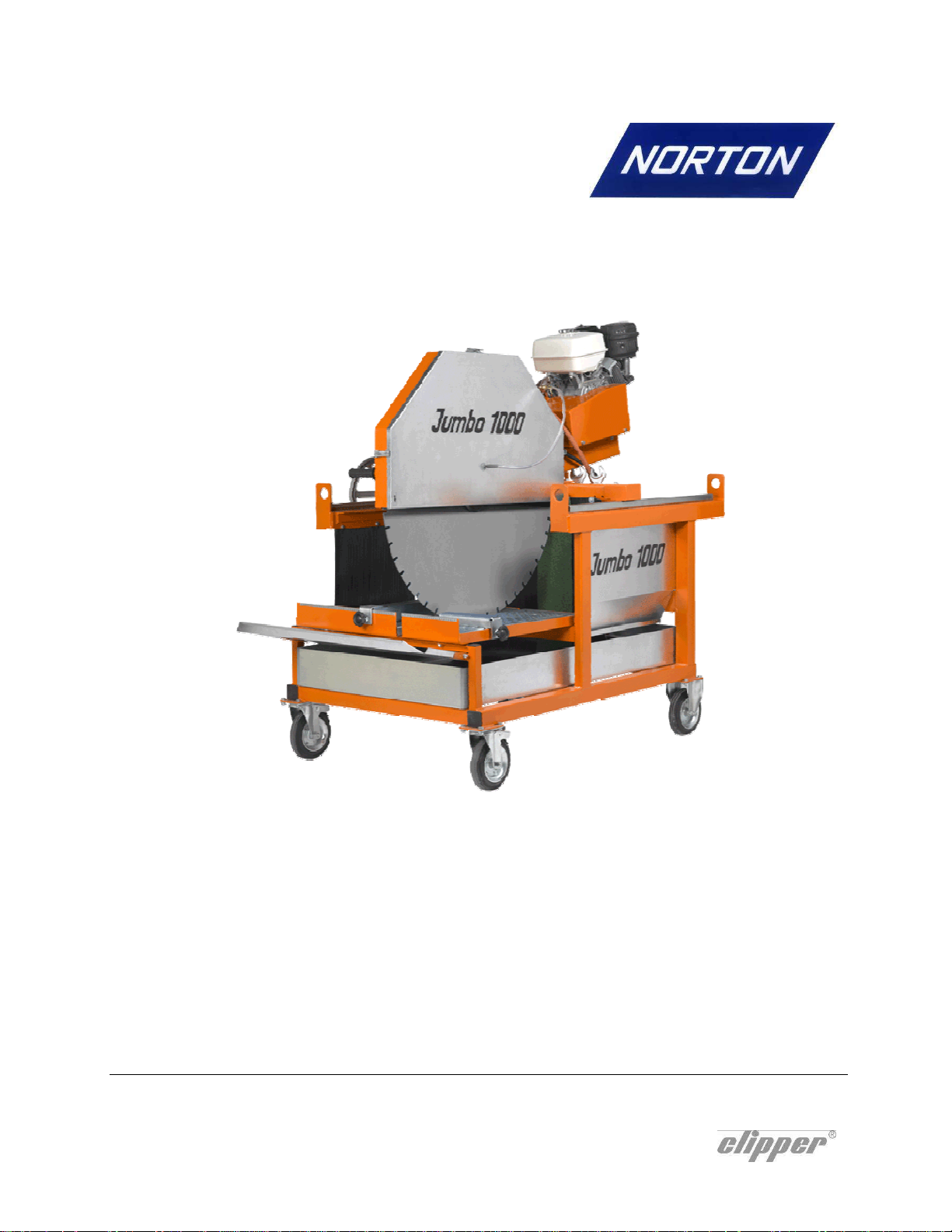
Jumbo 1000 P13
OPERATING INSTRUCTIONS
Page 2

2
Page 3

Declaration of conformity
The undersigned manufacturer:
SAINT - GOBAIN ABRASIVES S.A.
Declares that this product:
190, BD J.F. KENNEDY
L- 4930 BASCHARAGE
Masonry Saw:
Jumbo 1000 P13
Codes:
70184629335
70184629661
is in conformity with the following Directives:
• European Machinery Directive 2006/42/EC
• Electromagnetic Compatibility Directive 2004/108/EC
and European standard:
• EN 12418 – Masonry and stone cutting-off machines – Safety
Pierre Mersch
Business Manager Machines Europe
3
Page 4

4
Page 5

JUMBO 1000 P13
OPERATING INSTRUCTIONS AND SPARE PARTS LIST
1 Basic Safety Instructions 6
1.1 Symbols 6
1.2 Machine plate 7
1.3 Safety instructions for particular operating phases 7
2 Machine description 8
2.1 Short description 8
2.2 Purpose of use 8
2.3 Layout 8
2.4 Technical Data 10
3 Assembly and commissioning 11
3.1 Tool assembly 11
3.2 Starting the machine 12
3.3 Water cooling system 13
4 Transport and storing 14
4.1 Securing for transport 14
4.2 Transport procedure 14
4.3 Long period of inactivity 14
5 Operating the machine 15
5.1 Site of work 15
5.2 Cutting methods 15
6 Maintenance and servicing 17
6.1 Maintenance of the machine 17
6.2 Maintenance of the engine 18
7 Faults: causes and cures 20
7.1 Fault-finding procedures 20
7.2 Trouble-shooting guide 21
7.3 Customer service 21
8 Appendix Error! Bookmark not defined.
8.1 Spare parts list Error! Bookmark not defined.
8.2 Exploded parts drawings Error! Bookmark not defined.
5
Page 6
1 Basic Safety Instructions
The Jumbo 1000 P13 is exclusively designed for the cutting of construction products mainly on
construction sites.
Uses other than the manufacturer's instructions shall be considered as contravening the
regulations. The manufacturer shall not be held responsible for any resulting damage. Any risk shall
be borne entirely by the user. Observing the operating instructions and compliance with inspection
and servicing requirements shall also be considered as included under use in accordance with the
regulations.
1.1 Symbols
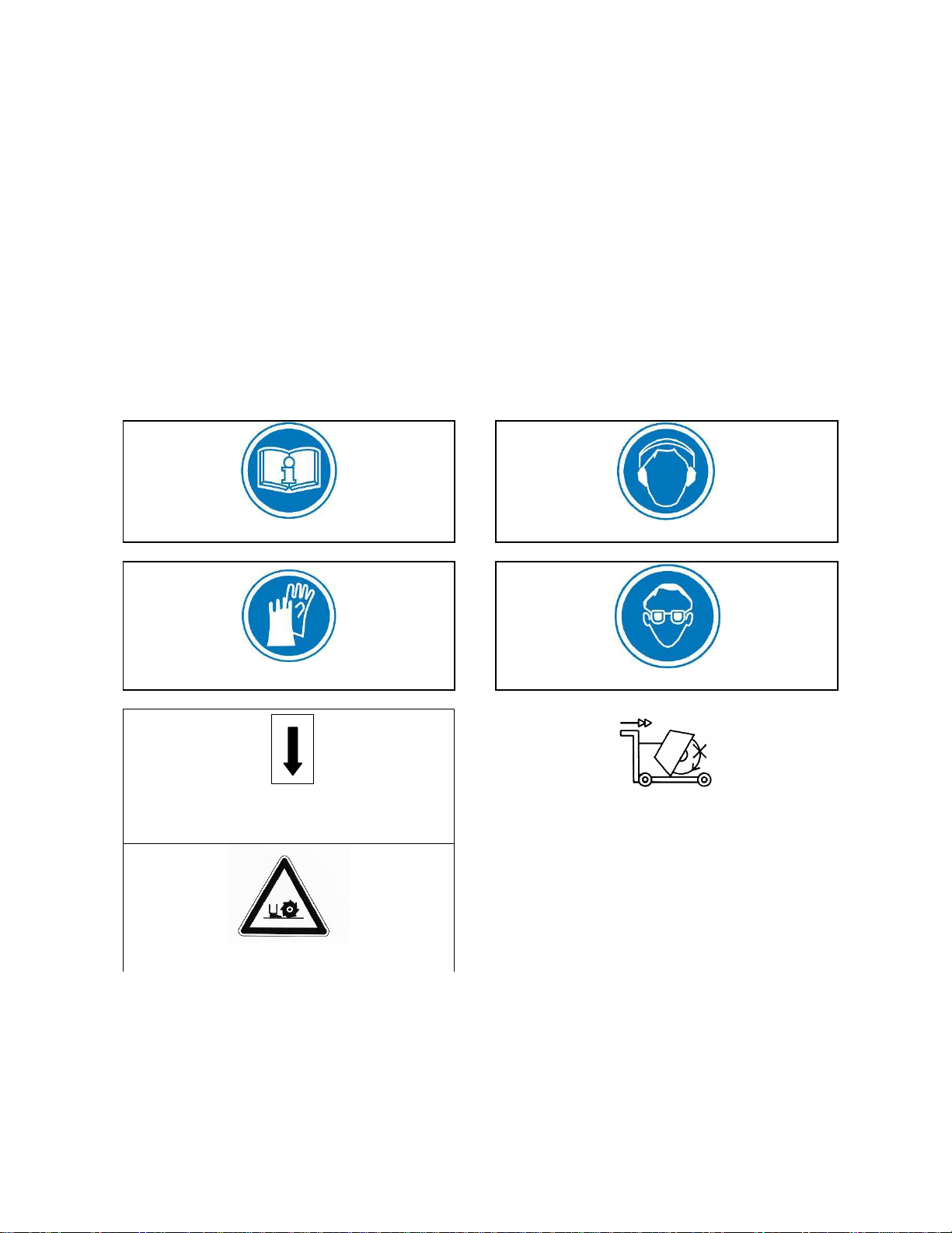
Important warnings and pieces of advice are indicated on the machine using symbols. The following
symbols are used on the machine:
Read operator’s instructions Ear protection must be worn
Hand protection must be worn Eye protection shall be worn
Rotation direction of the blade
Never move the machine with the blade
running idle.
Danger: risk of cut
6
Page 7
1.2 Machine plate
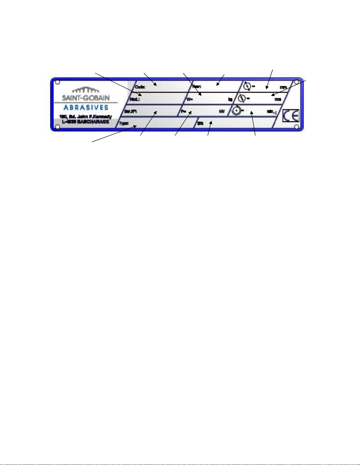
Important data can be found on the following plate located on the machine:
Machine Model Machine Code Weight
Machine type Serial number Power Safety standard Blade speed
Year of production
Maximum blade diameter
Bore
diameter
1.3 Safety instructions for particular operating phases
Before commencing work
• Before commencing work, make yourself familiar with the working environment at the place of
use. The working environment includes: obstacles in the area of work and manoeuvre, the
firmness of the floor, necessary protection at the site relating to public thoroughfares and the
availability of help in the event of accidents.
• Site the machine on an even, firm and stable base!
• During work, apply the brakes located on two of the four wheels.
• Check for correct mounting of the blade regularly.
• Immediately remove damaged or badly worn blades, as they endanger the operator whilst
rotating.
• The material to be cut must be held securely in place on the cutting table allowing no movement
during cutting operation.
• Always cut with the blade guard in position.
• Only fit NORTON diamond blades to the machine! The use of other tools can damage the
machine!
• Read the blades’ specifications carefully to choose the correct tool for your application.
• Attention is drawn to the use of BS2092 safety goggles in conformity with specified Processes
No.8 of the Protection of Eyes Regulation 1974, Regulation 2(2) Part 1. Also use other safety
equipment as mentioned in point 1.1 plus a dust mask when dry cutting is applied.
7
Page 8
2 Machine description
Any modification, which could lead to a change in the original characteristics of the machine, may
be done only by Saint-Gobain Abrasives who shall confirm that the machine is still in conformity
with the safety regulations.
2.1 Short description
The JUMBO 1000 P13 block saw is designed for durability and high performance for onsite wet
cutting operations of a wide range of masonry, refractory and natural stone products.
As with all other NORTON products, the operator will immediately appreciate the attention given to
detail and quality of materials used in construction. The machine and its component parts are
assembled to high standards assuring long life and minimum maintenance.
2.2 Purpose of use
The machine is designed for cutting a large range of building and refractory materials. It is not
designed for cutting wood or metals.
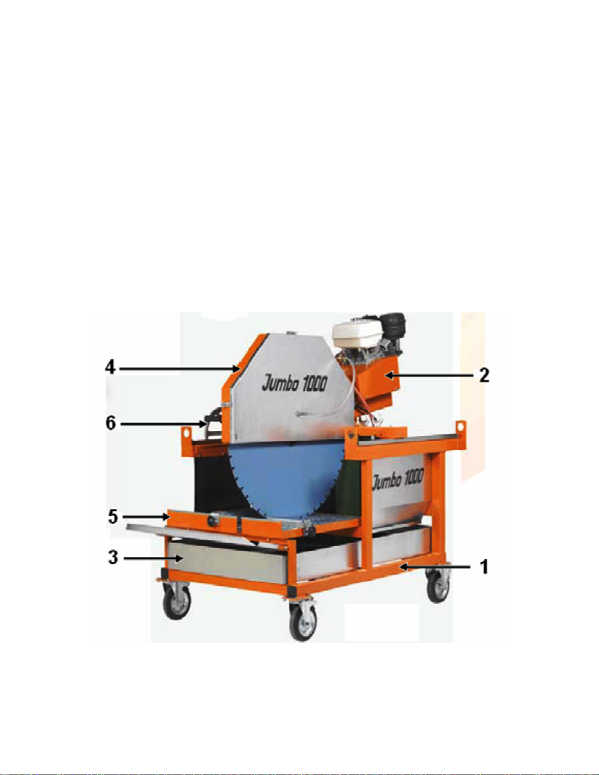
2.3 Layout
Frame (1)
Jig-welded, reinforced and all-steel construction ensures perfect rigidity. The frame includes a large
capacity water tray with drain plug. Frame has built-in lift brackets for easy transportation and is
mounted on 4 wheels, 2 of which have a locking device to secure the machine during cutting.
8
Page 9

Cutting head (2)
Jig-welded steel console equipped with pivot bar fixed to frame upright and housed in heavy-duty
bearings. Console supports the electric motor, the belt drive with its guard and the blade shaft
assembly. Bearings are machined for perfect fit and alignment. Precision-machined blade shaft
held in ball bearings and is driven by three heavy-duty V-section drive belts. The blade shaft
assembly is completely enclosed in a cutting head console, accessible for inspection by way of a
removable plate. The removable blade flange is tightened by means of a hexagonal nut. The
spring-loaded cutting head ensures smooth lowering of the cutting head. A depth-locking device
fixed to cutting head and frame enables the operator to set the cutting head to desired or to
maximum cutting depth. The movement of the head is ensured by a handwheel (6).
Water cooling system (3)
The coolant system comprises:
• A powerful mechanical water pump
• Plastic suction pipe delivering the water from the water pan to the cutting head
• A large capacity water pan (pan is galvanised) supplied with drain plug
• A water-tap, fitted to the blade guard, permitting controlled water flow
• Two water nozzles located on the blade guard ensure adequate flow of water to both sides of
the cutting blade
• Water curtains, fixed to frame and blade guard to restrict water spray and to minimise water
loss
Attention: The water pump must never run without water.
Blade guard (4)
Jig-welded steel construction with 1000mm-diameter blade capacity, offers maximum operator
protection and increased visibility of the work piece. Incorporated in the blade guard is an outer
detachable metal cover, which permits easy access to shaft for inspection and blade replacement
when motor is switched off, while fully protecting the blade when in operation.
Cutting table (5)
Large, heavy-duty and galvanised table fitted with water flow-control vents. The table is equipped
with a backstop and with a guide-a-cut device.
9
Page 10

2.4 Technical Data
Motor Honda GX390 9,7kW (13HP)
Fuel Automotive unleaded gasoline
Honda 4-Stroke, or equivalent high detergent, premium quality
motor oil certified to meet or exceed U.S. automobile
Oil
manufacturer’s requirement for service classification SG, SF.
(SG, SF designated on the oil container).
SAE 10W-30 recommended
Max. blade diameter
Bore
Cutting length mm
Cutting depth mm
Table dimension
Flange diameter
Blade shaft speed
Machine dimensions
Weight
Max. operating weight
Sound pressure level
Sound energy level
1000mm
60mm
720mm
420mm
720x800mm
160mm
928 min-1
2000x1080x1700mm
370 kg
430 kg
88 dB (A) (according to ISO EN 11201)
105 dB (A) (according to ISO EN 3744)
10
Page 11

3 Assembly and commissioning
The machine is delivered fully equipped and assembled and is ready for operation after connection
to the appropriate power supply.
3.1 Tool assembly
Use only NORTON blades with a maximum diameter of 1000 mm on the Jumbo 1000 P13.
All tools used must be selected with regard to their maximum permitted cutting speed for the
machine’s maximum permitted rotation speed.
Switch off the engine before mounting a new blade into the machine.
To mount a new blade, follow these steps:
• Disconnect water hoses from the blade guard.
• Retract outside cover of blade guard.
• Loosen the hexagonal nut on the blade shaft while holding the shaft (with the two 36mm
spanners supplied with the machine), which holds the removable outer flange.
• Remove the outer flange.
• Clean the flanges and blade shaft and inspect for wear.
• Mount the blade on arbour ensuring that direction of rotation is correct. Wrong direction of
rotation blunts the blade quickly.
• Replace outer blade flange.
• Tighten hexagonal nut while holding the shaft with spanners supplied for this purpose.
• Shut retractable blade guard cover and reconnect water hoses.
ATTENTION: The blade bore must correspond exactly to the diameter of the blade shaft. Cracked
or damaged bore is dangerous for the operator and for the machine.
11
Page 12
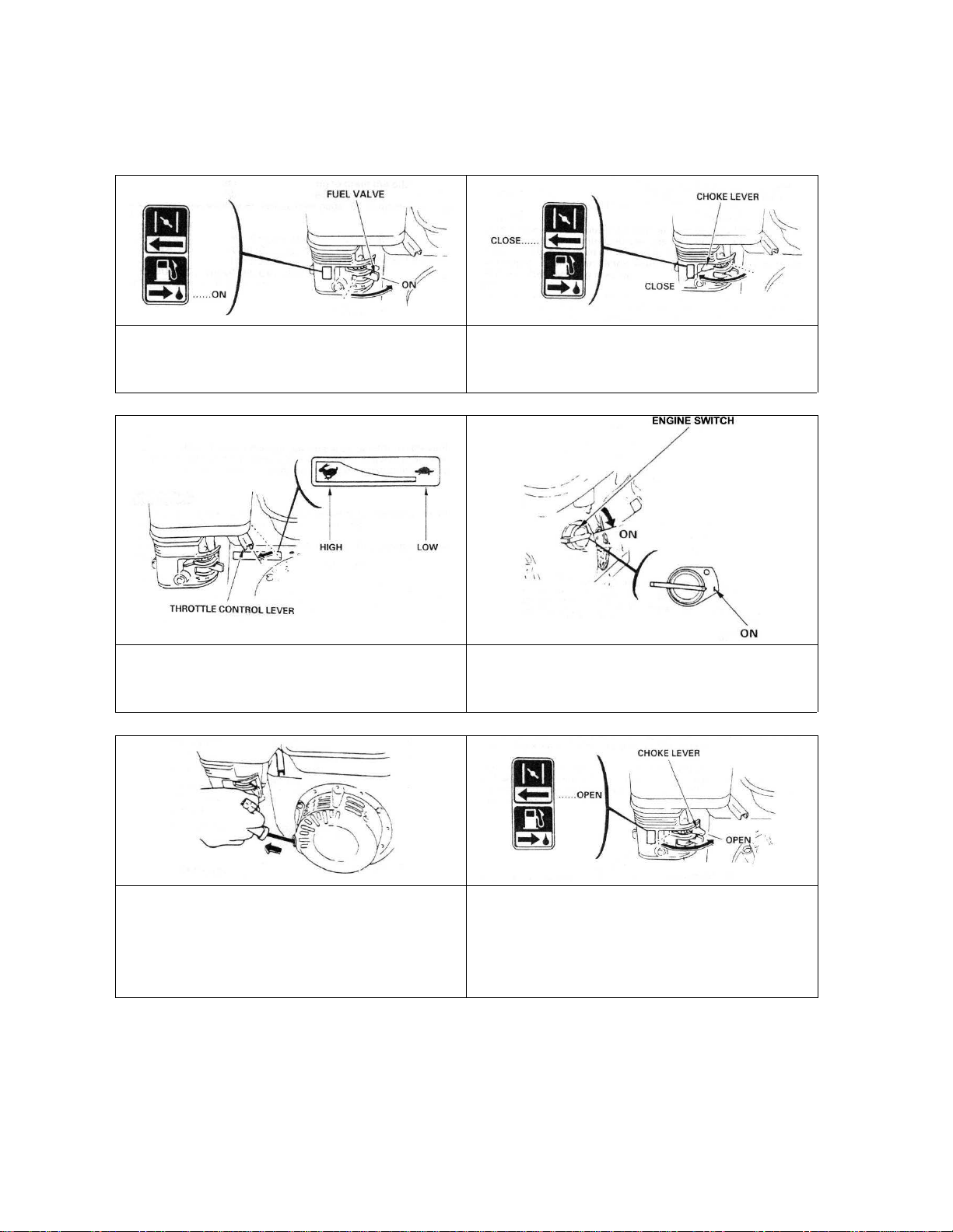
3.2 Starting the machine
Make sure that the blade does not touch the cutting table when you start the engine.
Turn the fuel valve to the ON position. Move the choke lever to the CLOSED position.
NOTE: do not use the choke if the engine is
warm or the air temperature is high.
Move the throttle control lever slightly to the
left.
Put the engine switch on ON, and make sure
the emergency switch on the board of the
machine is in the correct position.
Pull the starter grip lightly until you feel
resistance, then pull briskly.
CAUTION: Do not allow the starter grip to
snap back against the engine. Return it gently
to prevent damage to the starter.
To stop the engine, move the throttle control lever fully to the right, then turn the engine switch to
the OFF position. Turn the fuel valve to the OFF position.
12
As the engine warms up, gradually move the
choke lever to the OPEN position.
Position the throttle control lever for the
maximum engine speed.
Page 13

3.3 Water cooling system
Fill the water pan with clean water to approximately 2,5cm from top (ensure that bottom of pump is
fully immersed in water).
Open water-tap at blade guard (note that handle on water-tap should be in line with water-flow).
Ensure that water is flowing freely in the circuit and is delivered adequately to both sides of the
blade, as insufficient water supply may result in premature failure of the diamond blade.
Do not run the water pump without water. Always make sure that there is enough water in the pan
and refill if necessary.
In case of frost, empty the water cooling system.
13
Page 14

4 Transport and storing
Take the following measures in order to transport the JUMBO 1000 P13 securely.
4.1 Securing for transport
Before transporting or lifting the machine, always remove the blade and empty the water pan.
Secure the head with the locking hook and handle.
4.2 Transport procedure
The machine can be moved on a flat surface using its wheels. Only use the lift brackets to lift the
machine, as other parts of the machine are not designed for this purpose.
4.3 Long period of inactivity
If the machine is not going to be used for a long period, please take the following measures:
• Completely clean the machine
• Loosen the drive belts
• Empty the water system
• Take the water pump out of the slurry and clean it thoroughly.
The storage site must be clean, dry and at a constant temperature.
14
Page 15
5 Operating the machine
5.1 Site of work
5.1.1 Siting the machine
• Remove from the site anything, which might hinder the working procedure!
• Make sure the site is sufficiently well lit!
• Make sure you have a continual adequate view of the working area so you can intervene in the
working process at any time!
• Keep other staff out of the area, so you can work securely.
5.1.2 Space required for operation and maintenance
Leave 2 m in front of the machine and 1, 5 m around it for usage and maintenance of the Jumbo
1000 P13
5.2 Cutting methods
To use the machine correctly, you must be on the side of the machine with one hand on the
handwheel, and the other ready to stop the machine in case of emergency. Always keep your
hands away from the moving blade.
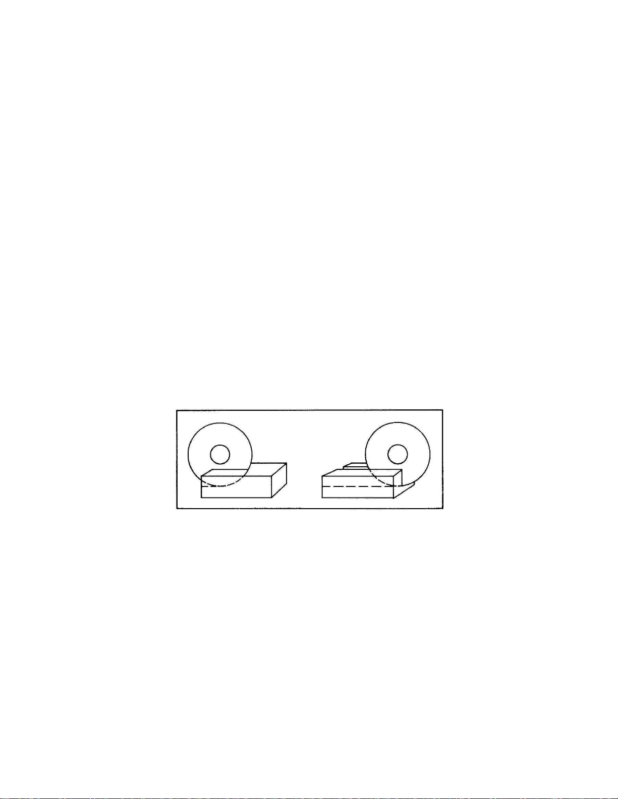
• Lower the cutting head to the desired cutting depth (in “through cutting”, lower cutting head until
blade periphery reaches max. 3-5mm under the surface of the cutting table) by means of the
handle on the blade guard and the scale over the head.
• Fix position by tightening the clamping device.
• Put material on cutting table.
• Start the engine (see point 3.2)
• Turn the handwheel slowly and without undue pressure towards the rotating blade and cut the
material.
• When your cut is finished, turn the handwheel so that the blade is completely out of the material
before stopping the machine.
REMARK: If the full depth of cut requires excessive pressure (on very dense material e.g.) make 2
or 3 shallow cuts.
15
Page 16

5.2.1 General advice for the cutting
• Make sure you have filled the water and the fuel tank. No petrol is supplied with the machine.
• The engine is shipped with oil. Check oil level before starting. Top up if required.
• Material weighing up to 100 kg and having dimensions smaller than 720x800x370mm can be
cut with the Jumbo 1000 P13.
• Before commencing work make sure the diamond blade is firmly seated!
• Select the right diamond blade as recommended by the manufacturer depending on the
material to be worked, the working procedure (wet cut) to be carried out and the required
efficiency.
• Apply cooling water continuously whilst cutting and in good time!
• When cutting work is finished, close the water-tap so you can remove the cut pieces from the
cutting table without getting wet.
16
Page 17
6 Maintenance and servicing
6.1 Maintenance of the machine
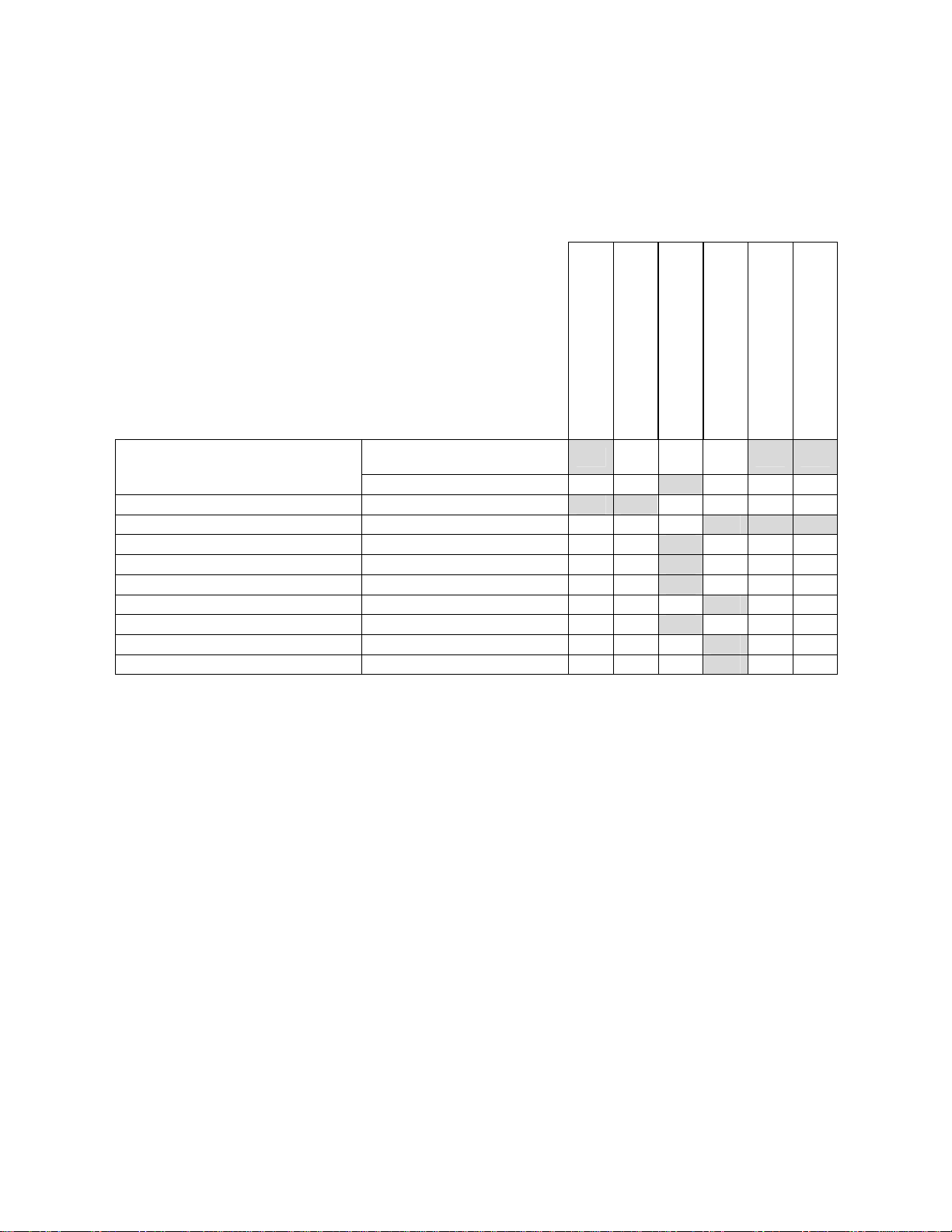
To ensure a long-term quality from the cutting with the Jumbo 1000 P13, please follow the
maintenance plan below:
Begin of the day
During the changing of the tool
End of the day
Every week
After a fault
Visual control (general aspect,
Whole machine
Flange and blade fixing devices Clean
Belts tension Check tension and adjust
Water pan Clean
Water pump Clean
Water hoses and nozzles Clean
Water pump filter Clean
Head guiding bars Clean
Motor housing Clean
Reachable nuts and screws Tighten up
water tightness)
Clean
Maintenance of the motor
Always perform the maintenance with the motor switched off.
Adjustment and replacement of the belts
To adjust the belts, firstly remove the belt guard by unscrewing the 6 nuts. Loosen the 4 motor bolts
and shift the motor by using the two screws on the side.
To replace the belts, move the motor completely forward. Adjust the belts and retighten them by
shifting the motor to the left.
Always use a matched set of belts. Do not replace single belts.
Lubrication
The Jumbo 1000 P13 uses life-lubricated bearings. Therefore, you don’t need to lubricate the
machine at all.
Cleaning of the machine
Your machine will last longer if you clean it thoroughly after each day of work, especially water
pump, water pan, motor, blade flange and cutting head rails.
After a damage
17
Page 18
6.2 Maintenance of the engine
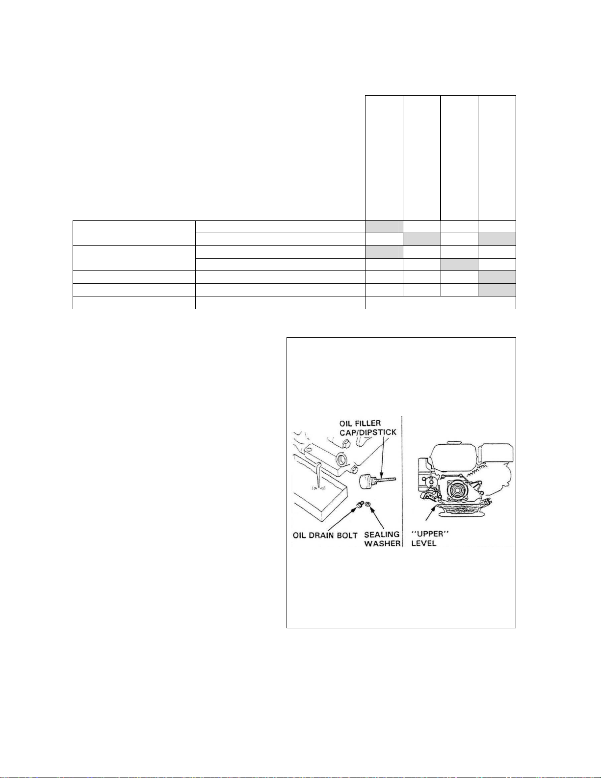
Regular service period
Perform at every indicated month or
operating hour interval, whichever comes
first
Engine oil
Air cleaner filter
Fuel strainer cup Clean
Spark plug Check-Clean
Fuel line Check (Replace if necessary) Every 2 years
Check level
Change
Check
Clean
Each use
First month or 20 hours
Every 3 months or 50 hours
Engine oil
To change the oil,
• Remove the oil filler cap/dipstick and
drain bolt.
• Allow the oil to drain completely.
• Please dispose of used motor oil in
a manner that is compatible with
the environment. We suggest you
to take used oil in a sealed
container to your local recycling
centre or service station for
reclamation. Do not throw it in the
trash, pour it on the ground or
down in a drain.
• Reinstall the drain bolt, and tighten it
to 18 N.m.
• Fill the crankcase with the engine oil
to the outer edge of the oil filler neck.
• Reinstall the filler cap/dipstick.
Every 6 months or 100 hours
18
Page 19
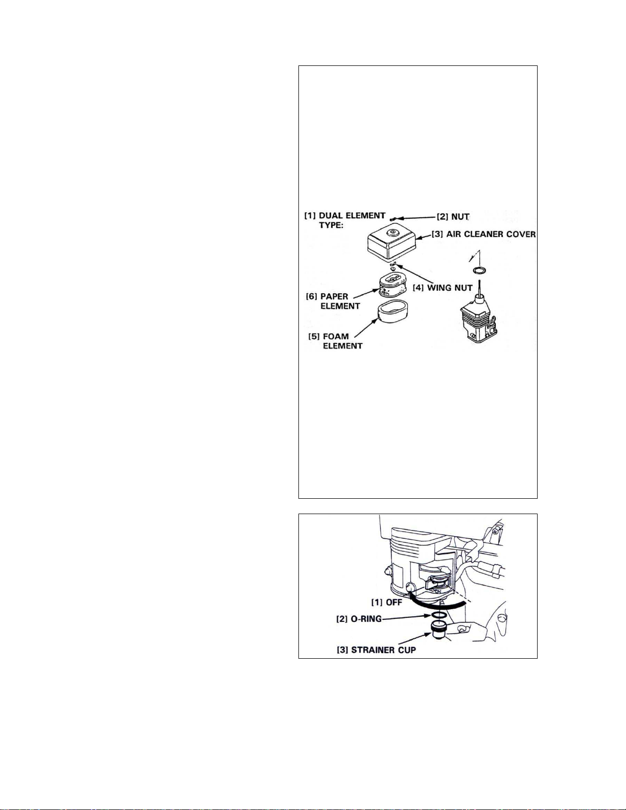
Air cleaner
The JUMBO 1000 P13 has a dual type
filter.
To service the air cleaner filter, follow
these instructions:
• Remove the nut, air cleaner cover and
wing nut.
• Remove the pre air cleaner elements
and separate them.
• Carefully check both elements for
holes or tears and replace if damaged.
Paper element:
• Tap element lightly several times on a
hard surface to remove excess dirt
• Blow compressed air lightly through
the filter from the inside out.
• Never brush the dirt off; brushing will
force dirt into the fibres.
Foam element:
• Clean in warm soapy water, rinse and
allow to dry thoroughly.
• Dip the element in clean engine oil
and squeeze out all the excess. The
engine will smoke during initial startup if too much oil is left in the foam.
• Shine a light through the elements,
and inspect them carefully.
Reinstall the elements if they are free of
holes and tears.
Fuel strainer cup
To service fuel strainer cup, follow these
instructions:
• Turn off the fuel valve and remove the
strainer cup.
• Clean the strainer cup with solvent.
• Install the O-ring and strainer cup.
• Tighten the strainer cup to 4N.m.
19
Page 20
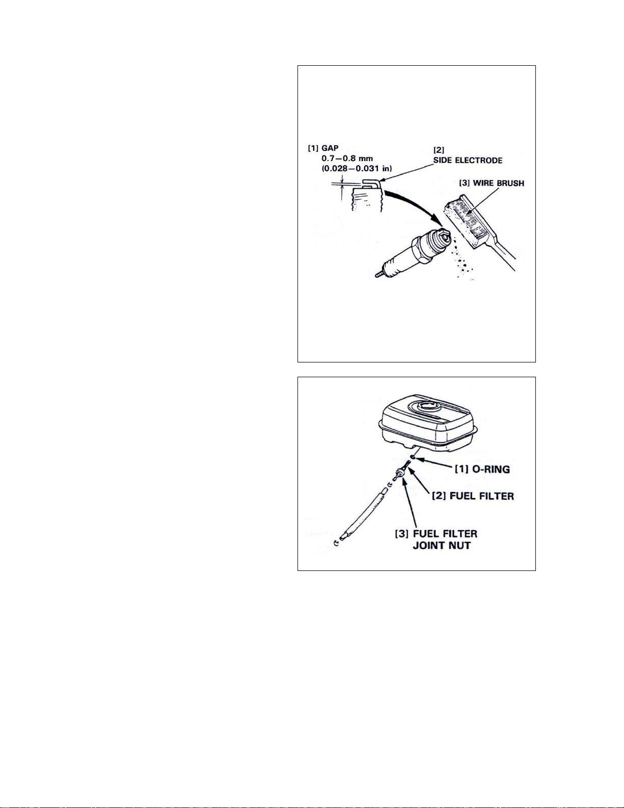
Spark plug
To service the spark plug, follow these
instructions:
• Visually inspect the spark plug.
Discard the plug if the insulator is
cracked or chipped.
• Remove carbon or other deposits with
a stiff wire brush.
• Measure the plug gap with a wire-type
feeler gauge. If necessary, adjust the
gap by bending the side electrode.
• Make sure the sealing washer is in
good condition; replace the plug if
necessary.
• Install the plug finger tight to seat the
washer, then tighten with a plug
wrench (an additional ½ turn if a new
plug) to compress the sealing washer.
If you are reusing a plug, tighten 1/81/4 turn after the plug seats.
Fuel line
To service the fuel line, follow these
instructions:
• Drain the fuel into a suitable container,
and remove the fuel tank.
• Disconnect the fuel line, and unscrew
the fuel filter from the tank.
• Clean the filter with solvent, and
check, that the filter screen is
undamaged.
• Place the O-ring on the filter and
reinstall. Tighten the filter to 2N.m.
After reassembly, check for fuel leaks.
Further maintenance
For further maintenance, please contact the nearest engine maintenance centre.
7 Faults: causes and cures
7.1 Fault-finding procedures
Should any fault occur during the use of the machine, turn it off.
20
Page 21
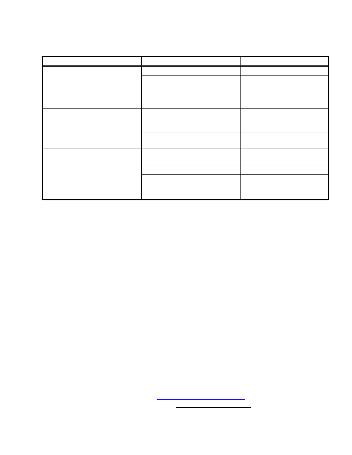
7.2 Trouble-shooting guide
Trouble Possible source Resolution
Hard starting
Blade is not turning Belts not tightened or defective Check the belts tension and
No water on the blade
Not enough fuel Fill fuel tank
Fuel filter clogged Clean fuel filter
Spark plug faulty Inspect spark plug
Stronger fault Contact nearest engine
maintenance centre
change them if needed
Air filter restricted Clean or replace air filter Engine lacks power
Stronger fault Contact nearest engine
maintenance centre
Not enough water in the pan Refill the water pan
Water tap is closed Open tap on blade guard
Water supply system is blocked up Clean water supply system
Water pump is not working
• Check if pump pulley is
driven by the belts
• Change the pump
7.3 Customer service
When ordering spare parts, please mention:
• The serial number (7 digits).
• The code of the part.
• The exact denomination.
• The number of parts required.
• The delivery address.
• Please indicate clearly the means of transportation required such as "express" or "by air".
Without specific instructions, we will forward the parts through the means which seem
appropriate to us --- but which is not always the quickest way.
Clear instructions will avoid problems and faulty deliveries.
If not sure, please send us the defective part.
In the case of a warranty claim, the part must always be returned for evaluation.
Spare parts for the motor can be ordered with the manufacturer of the motor or with their dealer,
which is often quicker and cheaper.
This machine has been manufactured by Saint-Gobain Abrasives S.A.
190, Bd. J. F. Kennedy
L- 4930 BASCHARAGE
Grand-duché de Luxembourg.
Tel. : 00352-50401-1
Fax : 00352- 50 16 33
http://www.construction.norton.eu
e-mail: [email protected]
21
Page 22

Guarantee can be claimed and technical support obtained from your local distributor where
machines, spare parts and consumables can be ordered as well:
Benelux and France:
From Saint-Gobain Abrasives S.A.
Free telephone numbers:
Belgium : 0 800 18951
France: 0 800 90 69 03
Holland: 0 8000 22 02 70
e-mail: [email protected]
Czech Republic
Norton Diamantove Nastroje Sro
Vinohrdadska 184
CS-13000 PRAHA 3
Tel: 0042 0267 13 20 21
Fax : 0042 0267 13 20 21
e-mail : [email protected]
Spain
Saint-Gobain Abrasivos S.A.
Ctra Guipuzcoa km7,5
E-31195 BERRIOPLANO (Navarra)
Tel: 0034 948 30 3000
Fax: 0034 948 30 6042
e-mail:[email protected]
Italy
Saint-Gobain Abrasivi S.p.A.
Via per Cesano Boscone, 4
I-20094 CORSICO-MILANO
Tel: 0039 02 44 851
Fax : 0039 024 51 01 238
e-mail : [email protected]
United Kingdom
Saint-Gobain Abrasives Ltd.
Doxey Road
Stafford
ST16 1EA
Tel : 0845 602 6222
Free fax : 0800 622 385
e-mail : [email protected]
Germany
Saint-Gobain Diamond Products GmbH
Birkenweg 45-49,
D-50389 WESSELING
Tel : (02236) 8911 0
Fax : (02236) 8911 30
e-mail: [email protected]
Austria
Saint-Gobain Abrasives GmbH
Telsenberggasse, 37
A-5020 SALZBURG
Tel : 0043 662 43 00 76 77
Fax : 0043 662 43 01 75
e-mail: [email protected]
Poland
Saint-Gobain Diamond Products Sp.zO.O.
AL. Krakowska 110/114
PL-00-971 WARSZAWA
Tel: 0048 22 868 29 36
Tel/Fax: 0048 22 868 29 27
e-mail: [email protected]
Hungary
Saint-Gobain Abrasives KFT.
Banyaleg Utca 60B
H-1225 BUDAPEST
Tel: ++36 1 371 2250
Fax: ++36 1 371 2255
e-mail: [email protected]
22
Page 23

23
Page 24

SAINT-GOBAIN ABRASIVES
190, Bd. J. F. Kennedy
L-4930 BASCHARAGE
LUXEMBOURG
Tel.: ++352 50401-1
Fax: ++352 501633
e-mail: [email protected]
www.construction.norton.eu
10.11.08
24
 Loading...