

Page 1
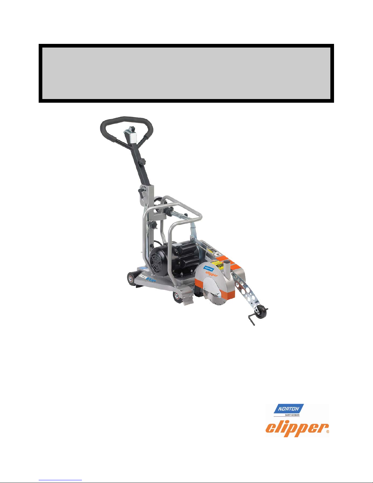
OWNERS
MANUAL
Joint Clean Out and Concrete Saw
MODEL:
GC25E UP
FORM << GC25E UP rev 8/2012
Page 2

WARRANTY
Norton warrants all products manufactured by it against defects in
workmanship or materials for a period of one (1) year from the date of
shipment to the customer.
The responsibility of Norton under this warranty is limited to replacement or
repair of defective parts at Norton's Stephenville, Texas factory, or at a
point designated by it, of such part as shall appear to us upon inspection at
such point, to have been defective in material or workmanship, with
expense for transportation borne by the customer.
In no event shall Norton be liable for consequential or incidental damages
arising out of the failure of any product to operate properly.
Integral units such as gasoline engines, electric motors, batteries, tires,
transmissions, etc., are excluded from this warranty and are subject to
the prime manufacturer's warranty.
This warranty is in lieu of all other warranties, expressed or implied, and all
such other warranties are hereby disclaimed.
Important: Before placing equipment in operation, record the following
information.
MODEL:_________ SERIAL NO.___________
PURCHASE FROM: _____________________
ADDRESS: ____________________________
CITY_______ STATE ______ ZIP ________
TELEPHONE NO. ______________________
Before using this equipment, make sure that person using it
read and understand the instructions in this owner’s manual.
2
Page 3

Table of Contents
CONTENTS PAGE
I. Preparation
A. Safety Precautions 4-6
B. Assembly 7
C. GC25E UP Joint Clean Out and Concrete Saw Specifications 8-9
D. Pointer Alignment 10
D. Electrical Connections GC25E UP 11-14
Power Connections 11
Generators 12
Wiring Diagram GC25E UP 12
Thermal Reset 12
Electrical Trouble Shooting 13-14
II. Operation
A. Installing The Blade 15-16
C. Operating The Saw 16-20
D. Cutting Technique 20
E. Green Concrete Cutting 20-21
III. Maintenance
A. 22
B. Bearings 22-23
C. V-Belts 23
D. Depth Control 23
E. Dust Removal System Adjustment 24-33
IV. Parts List Section
A. Ordering Information 24
B. Parts Drawing / Service Parts List 25-34
Blade Guard Assembly GC25E UP 25
Cutting Head Assembly GC25E UP 26
Blade Shaft Assembly GC25E UP 27
Depth Control Assembly GC55 and GC25E UP 28
Motor Assembly GC25E UP 29
Frame Assembly GC25E UP 30
Front Pointer Assembly GC25E UP 31
Main Assembly GC25E UP 32-34
15-18
22
24
Safety Alert Symbol: Information Following This Symbol Is Very
Important.
Use Only Norton Diamond Blades
Read Owners Manual Before Use
3
Page 4
I. PREPARATION
A. Safety Precautions
Important! The following safety precautions must always be observed.
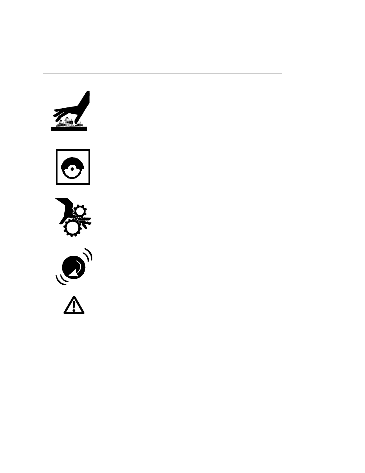
Hazard Symbols
Motor components can get extremely hot from operation. To prevent
burns, do not touch the engine or related parts while the engine is
running or immediately after it is turned off. Never operate the engine
with any heat shields or guards removed.
Keep all guards in place when operating any piece of equipment
Keep hands, feet, hair, and clothing away from all rotating parts
Never tamper with the governor components of settings to increase
the maximum speed. Severe personal injury and damage to the
engine or equipment can result if operated at speed above maximum.
Always obey the maximum speed rating of blade.
DO NOT LIFT THE SAW BY THE HANDLE BARS
4
Page 5

Dust and Silica Warning
Grinding/cutting/drilling of masonry, concrete, metal and other materials can generate
dust, mists and fumes containing chemicals known to cause serious or fatal injury or
illness, such as respiratory disease, cancer, birth defects or other reproductive harm. If
you are unfamiliar with the risks associated with the particular process and/or material
being cut or the composition of the tool being used, review the material safety data
sheet and/or consult your employer, the material manufacturer/supplier, governmental
agencies such as OSHA and NIOSH and other sources on hazardous materials and
make certain to comply with all product warnings and instructions for the safe and
effective use of the material being cut. California and some other authorities, for
instance, have published lists of substances known to cause cancer, reproductive
toxicity, or other harmful effects.
Control dust, mist and fumes at the source where possible. In this regard use good
work practices and follow the recommendations of the manufacturer/supplier,
OSHA/NIOSH, and occupational and trade associations. Water should be used for dust
suppression when wet cutting is feasible. When the hazards from inhalation of dust,
mists and fumes cannot be eliminated through engineering controls such as vacuum
and/or water mist, the operator and any bystanders should always wear a respirator
approved by NIOSH/MSHA for the material being cut.
Use Approved:
Eye Protection Hearing
Protection
Respiratory
Protection
5
Head Protection
Page 6
1. Before mounting any blade on the saw, the blade should be inspected for any
damage which might have occurred during shipment, handling or previous use.
2. The blade collars and arbors should be cleaned and examined for damage
before mounting the blade.
3. The blade must be properly fitted over the arbor with the drive pin on the
outside collar projecting through the drive pin hole on the blade and inside
collar.
4. The blade shaft nut, which is a left-hand thread nut, must be tightened securely
against the outside blade shaft collar.
5. The blade must be operated within the specified maximum operating speed
listed on the blade.
6. The blade guard must be in place with the nose guard dow n and locked when
the saw is running.
7. The operator should wear safety glasses and any other appropriate safety
equipment.
8. When starting the saw, the operator should stand away and to the side of the
blade.
9. If for any reason the saw should stall in the cut, raise the blade out of the cut.
Check the outside blade shaft collar and nut for tightness. Inspect the blade
for damage before restarting the saw. Use caution when resuming a cut. Be
certain that the blade is in alignment with the previous cut.
10.During cutting operations, do not exert excess side pressure on the handles as
a method of steering. Do not force the blade into the cut by lowering the blade
too fast or by pushing the saw too fast.
You Are Responsible For Your Safety!!!
6
Page 7
I. PREPARATION
B. Assembly
The GC25E UP compact Joint Clean Out and Concrete saws are shipped
completely assembled and ready for use except for diamond blade, Handle Bar
position, electrical extension cord (not supplied), and power supply. Inspect the saw
for shipping damage. If any damage is found, contact the shipper immediately and
file a freight claim. Saint-Gobain Abrasives, Inc. is not responsible for any freightrelated damages.
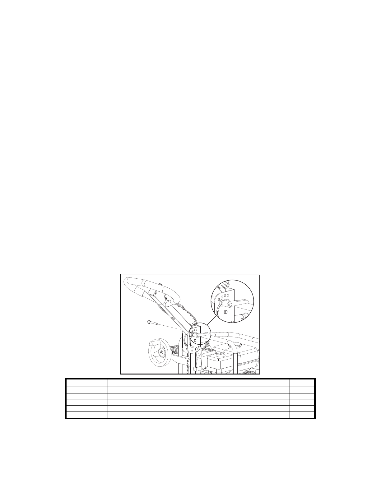
Adjust the Handle Bars Position:
1. Remove the GC25E UP from the box.
2. Remove the Quick Release Pin P/N: 241055 out of its retaining hole
3. Loosen the Black Knob P/N: 241054.
4. Rotate the Handle Bar from the lowered storage position to the desired
position.
5. Align the hole in the Handle Bar with the holes in the frame.
6. Attach the Quick Release Pin P/N: 241055 by pushing it through the hole in
the Frame and then the hole in the Handle Bar. Make sure that the Quick
Release Pin passes all the way through both sides of the Frame.
7. Tighten the Black Knob P/N: 241054.
Read and understand the remaining sections of this Owner's Manual. NOTE: Do not
install the blade until it is time to use the saw. ANSI regulations prohibit the
transportation of any concrete saw with the blade installed.
Part # Description QTY
241054 SCR 5/16-18 UNC X 2-1/2" CARRIAGE BOLT 1
241055 PIN QUICKRELEASE 5/16" X 2" GRIP LENGTH 1
241054 KNOB M8 X 1.25 ADJUSTABLE 1
232110 WASHER M8 DIN125 FLAT 1
241055 WASHER 3/8 WAVE 1
7
Page 8
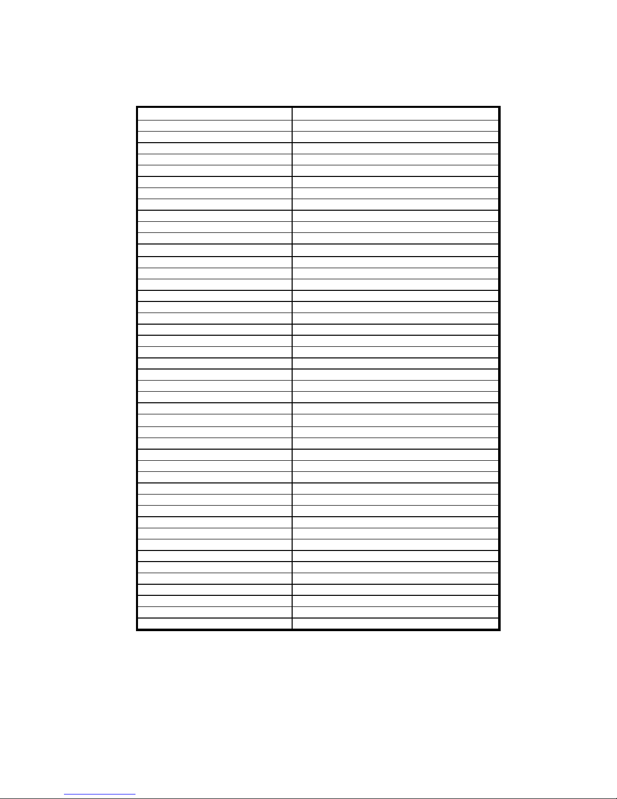
C. GC25E UP Series Joint Clean Out and Concrete Saw
Specifications
Dimensions/Weight GC25E UP
Length (Working) 42-23/32” (1,090mm)
Length (Transport) 32: (813mm)
Width 18-1/8" (460mm)
Height 42-23/32” (1,090mm)
Frame Width 18-1/8” (460mm)
Pointer Length 8-7/32”(209mm)
Blade To Wall 7-1/2” (190mm)
Wheel Base Length 19” (483mm)
Blade Shaft Maximum Height 9-41/64” (245mm)
Weight Created 155 lbs (71 kg)
Weight Uncreated 135 lbs (61 kg)
Power Source
Engine/Motor Mfg. Gangfon Motor
Spec No. Totally Enclosed Air Cooled Thermal Protection
Power Source Electric
Maximum Horse Power1 3 HP
Net Horse Power 3 HP
Max Torque -NAPower Source RPM 3450 RPM
Model Dual Voltage
Cooling System Forced Air
Voltage 115-230 volts
Cycles/Current/Phase 60Hz/AC/1
Full Load Amps (115/230 volts) 15/7.5 Amps
Starting Amps (115/230 volts)2 45/22.5 Amps
Starter Capacitor
Characteristics
Max Blade Ø10" (254mm)
Depth of Cut 10” (254 mm) 3.5" (88mm)
8” (203 mm) 2.5" (63mm)
Arbor Bore 5/8"
Blade Shaft Flange Diameter 3-5/64” (78mm)
Blade Shaft Speed 2905 rpm
Depth Control Hand Wheel With Screw Feed
Blade Rotation Counter Clock Wise (Up Cut)
Depth Lock Standard
Depth Gauge Standard
Number Of V-Belts 1
Blade Guard Type Screwed On, All Steel Construction
Cutting Side Center
Lifting Bale Built In
Handle Bars Adjustable, Stays Level At All Times
Wheels Non-marking
Wheel Size Front and Rear 3-3/8”x2-3/4”x25/32” (85x70x20mm)
1) Net Horsepower Rating provided by engine the manufacturer measured in accordance to SAE j1349 @ 3,600 RPM. The engine may vary from this value. Actual
horsepower on the machine will vary due to operating speed of engine, belt tension, environmental conditions, machine maintenance, and other variables.
2) Starting Amps are instantaneous – for best results use with a 30Amp circuit.
Vacuum Port Size 2” OD
8
Page 9

The GC25E UP Joint Clean Out and Concrete Saw was designed from the ground up to
be a High Performance Multiple Application saw. The GC25E UP is the best electric
Joint Clean Out saw on the market and is capable of cutting Cured Concrete and
Asphalt.
Used For Cutting Multiple Applications:
Joint Clean Out
Joint Widening
Cured Concrete
Asphalt
Features that make the GC25E UP a High Performance Joint Clean Out and
Concrete Saw:
Blade in center line of saw makes it easier to push and the machine tracks
straighter. The center line blade also helps the GC25E UP to roll straight while
cutting due to the blade being parallel to the blade.
Reinforced all steel frame reduces bending, flexing, and vibrations which can
damaged the concrete. The reinforced all steel frame is also stronger than the
competitive models
Soft Silicone Rubber wheels that are based off of a Norton Patient to absorb
vibrations that can create machine movement. The wheels also feature a
concave profile that helps the machine to roll over small objects with out
upsetting the blade.
10” maximum blade capacity with standard 5/8” arbor. The GC25E UP can be
used with 7” to 10” diameter Norton blades.
Hand Wheel with Depth Adjustment Screw & Depth allows precise depth
adjustments up to 3-1/2” deep when used with a 10” blade.
Fully adjustable dust removal Shroud system with standard vacuum hose
attachment helps to keep dust down.
Up cut helps with the extraction of dust when joint cleaning.
Front and rear pointers for precise alignment.
Handle Bar and Pointer folds up for compact easy transport.
Light in weight.
Dual voltage motor, change voltages from 115v to 230v by flipping a switch.
The GC25E UP is an extremely simple machine to operate.
The GC25E UP is designed for Joint Clean Out, Joint Widening, and cutting
multiple applications: such as Cured Concrete and Asphalt.
Includes a free 8” Joint Clean Out Blade.
9
Page 10

D. Pointer Alignment
1. Use a straight edge, and carefully mark a line 12 feet long on a smooth level
surface.
2. Place the saw blade on the marked line, move the saw to the center of the
marked line and then lower the blade until it is about 1/16” above the marked
line.
3. Measure from each end of the saw frame to insure that the frame is parallel to the
marked line. Adjust the saw as needed.
4. With the blade centered on the marked line and the saw frame parallel to the
marked line, lower the front pointer.
5. Adjust the nylon nuts until the pointer is aligned with the marked line.
10
Page 11
E. Electrical Connections GC25E UP
Important-Before connecting the motor leads to the power supply be sure that
the voltage, cycles and phase shown on the nameplate of the motor correspond
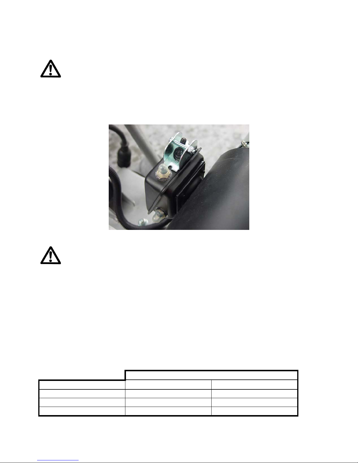
to the available power supply. The GC25E UP is equipped with a dual voltage
motor which runs on 115v or 230v 60Hz Single Phase Voltage. Either a 115-volt or 230
volt power supply can be used. To change voltage simply move the voltage change
switch located on the rear of the motor to the required voltage, no rewiring is required.
Wherever possible, use 230-volt power supply for best operation.
GC25E UP Voltage Change Switch (Shown in the 230v Position)
Failure to run the motor on the proper voltage will damage the motor and is not
covered under warranty. Improperly wired motors are not covered under
warranty.
The GC25E UP models are set for 115 Volt from the factory!!!
Power Connections
Connect the power supply to the pigtail leads of the switch. Direct wiring connection is
preferred, but an extension cord with an electrical plug with 30-amp capacity will give
the best performance. A 30-amp circuit breaker is recommended. Connecting wires
should be as short as possible and in one piece. For best performance use the GC25E
UP on a circuit with a 30A circuit breaker. If a 30A circuit is not available the use a 20A.
The GC25E UP will require up to 18A when under full load. In no case should the
connecting wires be longer than shown in the following table for use with the GC25E UP
Single-phase motors:
Wire Gauge 115 Volt 230 Volt
Number 12
Number 10
Number 08
25 ft (7.6 m) 100 ft (30.5 m)
50 ft (15.2 m) 150 ft (45.7 m)
75 ft (22.9 m) 175 ft (53.3 m)
Length Of Wire
11
Page 12
Caution-When wires that are too small gauge or too long are used, loss of power,
over heating, or possible damage to the motor will result. Damage or failure of
motors due to incorrect power supply cord lengths are not covered under any
warranty.
Always use the proper wiring connectors that are UL/CSA approved to attach
the motor to the electrical supply. Any wiring hook ups should be made by
qualified personal and made to National Electrical Code and to any Local
Codes.
Generators:
If a generator must be used, it must be of 8kW or larger. The generator must have a
30A circuit and capable of providing a minimum of 8kW at the required voltage. Under
size generators will cause motor damage and is not covered under warranty.
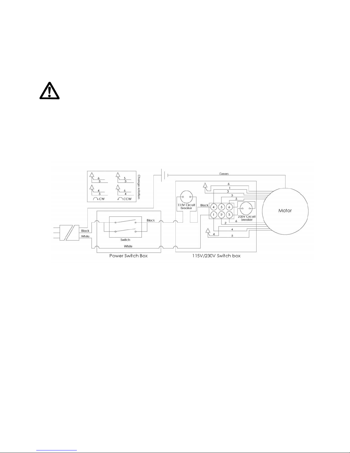
Wiring Diagram GC2E UP
Thermal Reset:
If the thermal reset engages this is a sign that the motor is over heating.
Continued over heating will damage the motor. The thermal reset will reset itself
once the motor is cooled. Do not force the thermal reset as it will damage the
reset and motor. The causes of the thermal reset activating are:
1. Too Long or Too Thin of Extension Cord (Low Voltage). Use the
correct length and gauge of Extension Cord.
2. Low Voltage Power Supply. Use a power supply with the correct
voltage.
3. Incorrect Blade of Application. Contact Norton Clipper’s customer
service or your local sales person for the correct blade specification
for your cutting application.
4. Overloading Machine. At a shallower depth. Make multiple passes
(Step Cutting) at no more than 1-1/2” deep. Cut at a slower forward
speed.
12
Page 13

Damage or failure of a motor due to continued over heating as the result of
incorrect extension cord length/size, incorrect power supply, incorrect
application, and continued overloading is not covered under warranty.
Electrical Trouble Shooting:
The following solutions depend largely on the total load on the circuit and operator
technique.
The following tips apply to all electrical motors and electrical powered products
regardless of application or manufacturer: 99.99% of machine issues are application
related, that is using the incorrect power supply, extension cords, operator technique, or
using the incorrect blade for the material being cut.
1. Verify the circuit breaker amperage. It is recommended that the circuit breaker
be at least 20A or higher for best performance. 30A will provide the best
performance.
2. Verify that the blade is NOT contacting the ground when starting the unit.
a. The blade should be above the ground when starting the saw.
b. If cleaning an expansion joint make sure that the blade is NOT contacting
the backer rod.
3. Extension Cord - Insure that the cord length and gauge is within the product
requirements. Incorrect cord gauges and lengths kill motors! Incorrect extension
cords create low voltage situations which cause the amperage to increase.
a. The best results will be a 50 foot or shorter 10 AWG or thicker (smaller
gauge number) extension cord set which is in one piece and in good
operating condition.
b. See section “Power Connections:” for addition extension cord
information.
4. The voltage range for the GC25E UP saw is 108v to 125v with 115 to 120v being
perfect. Lower than 108v will cause motor overheating, circuit breaker tripping,
and motor failure over time.
a. Verify the voltage at the machine NOT the rated or assume circuit voltage.
b. Low voltage kills motors!!! As voltage drops amps go up as amps go up
the internal temperature of the motor increases.
5. Verify the total load on the circuit. If above 15 amps move other equipment to
another, separate circuit. The GC25E UP saw pulls 7 to 8 amps with NO load,
as a load is applied the amp drawing will climb. Under full load (the point where
the motor starts to stall, it will draw 18A or more. The issue comes from the
circuit being over loaded (much greater than 15A for a long time, the exact trip
value will depend on the circuit breaker, age of breaker, and how many times it
has been tripped before).
a. If possible use a 20 amp circuit.
13
Page 14

b. Spread the tools over different circuits, especially the higher amperage
drawing products (Vacuums and saws).
6. Let the GC25E UP work for you. As you push it harder the motor will draw more
amperage which will over time trip the breaker. The motor with a medium
working load will pull around 13A and will run with no problem.
a. Do not force the machine, unlike the typical hand held tools typically used
for this application the GC25E UP does not need to for forced through the
joint.
b. When cutting do not over load the machine. The machine will sound like it
is working harder before the breaker trips. When the motor starts to labor
let off of the feed speed.
7. Also check the depth of cut -- max depth should be no more than 1.75".
a. Always step cut. Step cutting is the best operator technique as it creates
less load on the motor which means the motor will require less amperage,
the speed of cutting will increase, and the blade life will increase. Step
cutting saves time, saves money, increases tool life, and reduces job site
problems.
14
Page 15
II. OPERATION
A. Installing the Blade
1. Verify that the GC25E UP is disconnected from the power supply and that the
ON/OFF switch is in the “OFF” position.
2. Remove the 5/16”-18 UNC x ¾” Right Hand Thread Cap Screw, 5/16 Lock
Washer, 5/16 SAE Washer from the end of the blade (rotate Counter Clock Wise
- CCW).
3. Remove the 5/8”-11 Left Hand Thread Hex Nut (rotate Clock Wise – CW).
4. Inspect the Blade Collars for damage.
5. Inspect the Diamond Blade for the following:
a. Correct Diamond Blade for the material being cut
b. Direction of rotation
c. Stress Marks or Cracks – sign of overheating the blade. Do not use if
present replace the blade before use.
d. Heat Marks or bluing – sign of overheating the blade. Do not use if
present replace the blade before use.
e. Verify that all blade segments are in place and are in good working
condition.
6. Install the blade – NOTE Direction of rotation for the blade must be CCW (Up)
a. Make sure that both of the collars mating surfaces are clean and
undamaged – just like any other concrete saw.
Use only Norton Diamond Blades. This machine was not designed for the
use with abrasive blades.
7. Place the outer collar over the blade shaft – same as any other concrete saw –
make sure the flat mating surface faces the blade.
8. Attach and tighten the 5/8”-11 Left Hand Thread Hex Nut rotate CCW.
9. Attach and tighten the 5/16”-18 UNC x ¾” Right Hand Thread Cap Screw, 5/16
Lock Washer, 5/16 SAE Washer rotate CW.
10. Close the Blade Cover and tighten the Blade Cover Wing Nut.
11. You should be ready to go at this point.
NOTES: Never transport any concrete saw with the blade attached to the blade
shaft as the blade may be damaged during shipment.
15
Page 16

Blade Retaining System
Use Only Norton Diamond Blades
B. Operating the Saw
1. For blade installation instructions see section II. Operation sub heading A.
Installing the Blade. Electrical Connections see section E. Electrical
Connections GC25E UP
2. Loose the Depth Lock Thumb Screw ½ Turn.
3. Raise the saw to the full upright position. Do not let the blade come in contact
with the ground.
4. Maneuver the saw to the desired starting point.
a. Align the Front Pointer and Blade with the desired line of cut.
5. To start the machine: For Electrical Connections, Extension Cord Set
Information, and Generator Information see section E. Electrical
Connections GC25E UP
i. Verify that the motor voltage change switch is set to the same
voltage as the circuit.
ii. Verify that the circuit has a 30 Amp breaker installed.
iii. Verify that the extension cords are the correct gauge, length, and
are properly grounded.
16
Page 17

iv. Verify that the GC25E UP power switch in the “OFF” position.
v. Connect the extension cord set to the machine and power supply.
Follow all local and national electrical code. If unsure of how to
connect the extension cord set or of the electrical circuit have a
qualified Electrician make all electrical connections.
vi. Move the start switch to the “ON” position and the motor should
start. If the motor doe not start have a qualified Electrician inspect
all electrical connections and the power supply.
6. To set the Depth Gauge:
a. Slowly lower the Blade by rotating the Hand Wheel clockwise until the
Blade touches the work surface.
b. Loosen the Depth Gauge Thumb Screw.
c. Move the Depth Gauge to the “0” position. NOTE: When using smaller
diameter blades it may be necessary to align the Depth Gauge to the “1”
mark.
d. Tighten the Depth Gauge Thumb Screw.
e. Lower the machine by slowly rotating the Raise Lower Handle clockwise
until the desired depth of cut is reached.
7. Slowly lower the blade by rotating the hand wheel clockwise until the desired
depth of cut is reached. Use a reasonable rate of feed. Do not force the
blade into the cut!! If the engine starts to die slow down the rate of feed! If
the machine tries to climb out of the cut, slow down the rate of feed.
8. Adjusting the Dust Bellows: NOTE: Normally when the Dust Bellow is set for
the day there is no reason to readjust unless the blade has been removed or
the cutting depth has changed.
a. Turn the machine “OFF”.
b. Disconnect the Power Supply
c. Verify that the blade is properly installed.
d. Verify that the Blade Cover is closed and that the Blade Cover Thumb
Screw is tightened.
e. Loose the Dust Bellow front and rear Thumb Screw.
f. Lower the Dust Bellow until it touches the ground. NOTE: If the work
surface is uneven or has derbies the Bellow bottom surface can be
position 1/8” above the work surface.
g. Verify that the bottom edge of the Dust Bellows is parallel to the work
surface.
h. Tighten the front and rear Dust Bellow Thumb Screw.
17
Page 18
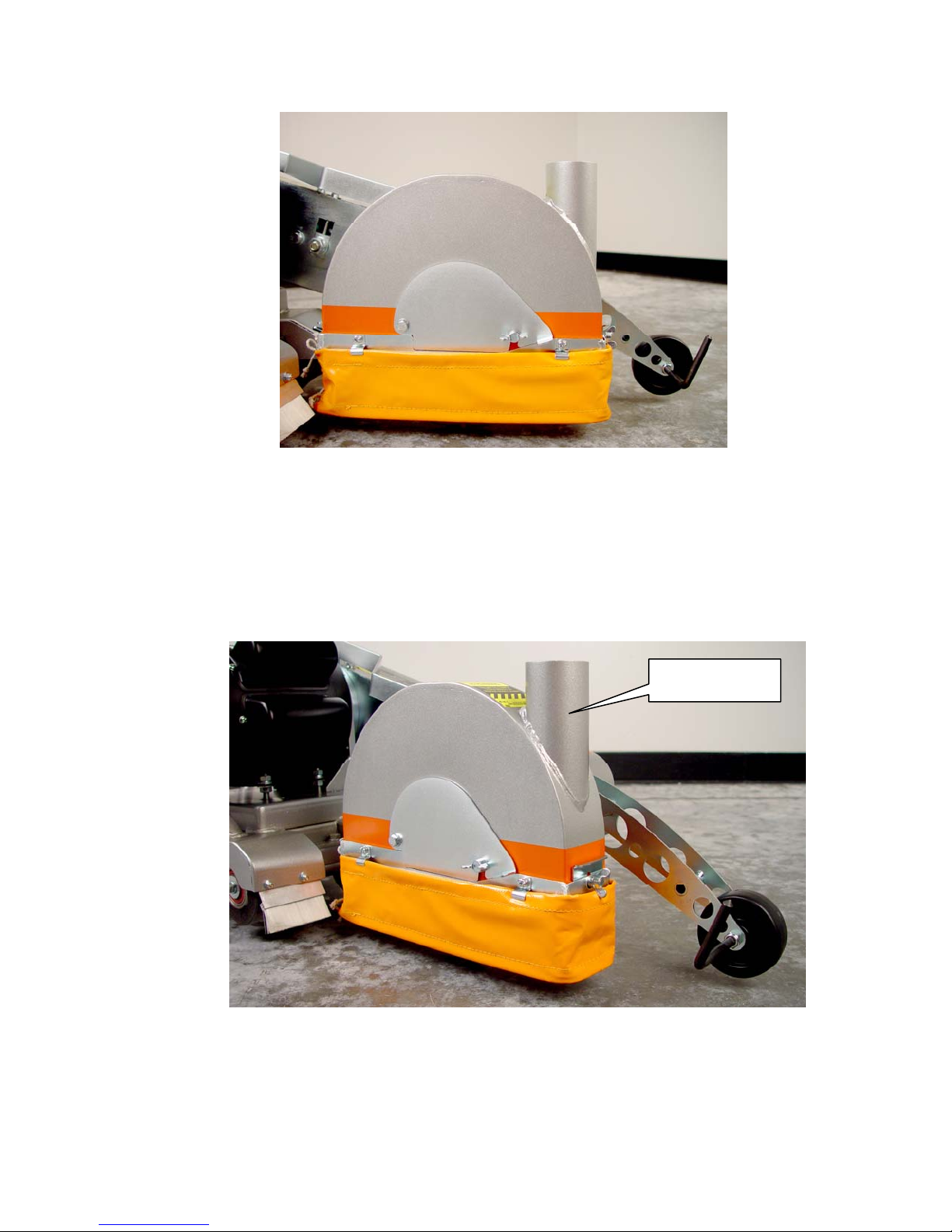
GC25E UP Dust Bellows Fully Extended
9. Vacuum Attachment:
a. Attach the Vacuum Hose to the Vacuum Port located on the front of the
Blade Guard.
b. If using a Vacuum Hose that is not 2” diameter an adapter may be
needed. Vacuum Adapters are available from your Vacuum supplier.
NOTE: The Vacuum Hose can be looped through the frame to help hold
the hose in place.
2” Vacuum Port
Vacuum Port Location
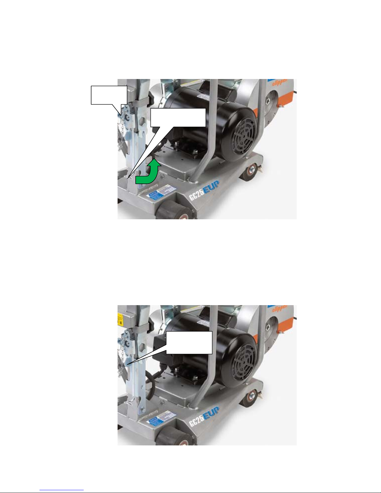
10. Connect the power supply to the machine. NOTE: The GC25E UP is
equipped with a Extension Cord Support. The Extension Cord Support will
hold the Extension Cord while using the machine. To use remove the Locking
18
Page 19
pp
Pin and rotate the Extension Cord Support 90° counter clockwise, and
reinstall the Locking Pin. Pass the Extension Cord through the pig tail located
on the end of the Extension Cord Support.
Locking
Pin
Extension Cord
Su
ort pig tail
Extension Cord Support
11. Turn the machine on.
12. Slowly move the machine forward
13. After cutting about 3’ lower the rear pointer into the joint. The rear pointer is
designed to slide into the joint path to help keep the GC25E UP in alignment
with the joint to be cleaned.
Rear Pointer
Location
19
Page 20

Rear Pointer
14. When the end of the cut is reached, slowly raise the blade out of the cut by
rotating the Hand Wheel counter-clockwise until the blade is at least one (1)
inch above the ground. Only move the saw in reverse with the blade in the
raised position.
15. When moving the saw to a new location, be sure the blade is not touching the
ground. Always pay close attention to where you are moving and where the
blade is at all times.
D. Cutting Technique
Lower the blade into the concrete to the required depth by turning the hand wheel
clockwise.
Push the saw steadily forward using the front pointer as a guide. Exert enough
forward pressure so that the engine begins to labor, but does not slow down. If the
saw begins to stall, reduce the forward movement until full rpm is restored to the
blade. If the saw stalls, raise the blade out of the cut before restarting. Avoid
excessive side pressure or twisting of the blade in the cut.
When cutting for best performance do not cut at more than 1-1/2” deep per pass.
Making multiple shallow passes will increase blade life, speed of cut, and decrease
engine/motor loads.
Additional Guide Lines For Sawing:
Understand and follow all of the instructions in this owner’s manual.
In critically hard aggregate, be careful not to feed too quickly as it may stall the
saw or ruin the cut.
If the saw stalls in the cut, immediately stop the forward speed and raise the
blade out of the cut. If this is not done the belts can fail or the blade may be
damaged.
Go slowly with a new blade until it opens up, that is, until the diamonds can be
seen and felt.
E. Joint Clean Out
The new Norton Clipper GC25E UP is specifically designed for Joint Clean Out. The
machine features a Center Line cut system that allows the machine to track
20
Page 21

straighter than competitive designs. In addition the machine features a vacuum port,
and dust Bellows to help keep air bore dust down to when compared to other
machines. The up cut blade rotation is utilized to help the vacuum system extract
the cutting particles.
Joint Clean Out Considerations:
1. Verify the voltage and circuit Amperage. See section E. Electrical Connections
GC25E UP for additional details. Connecting any electrical product to the
incorrect power source can result in product failure covered under any warranty.
2. If using an extension cord insure that it meets the length and gauge requirements
as stated in section E. Electrical Connections GC25E UP. Failure to use the
correct size extension cord can result in circuit breaker tripping, poor
performance, or motor damage which is not covered under any warranty.
3. Cut no deeper that 1-1/2” per pass for the best performance. If cutting deeper
per pass the forward cutting speed will need to be reduced. Do Not cut more
than 1-3/4” deep per pass. Diamond Blades will cut faster and last longer if
shallower cuts are made, aka Step Cutting.
4. Let the Blade cool off. Every few minutes stop the forward movement of the
machine and let the blade cool: cut for 2 to 5 minutes let the blade cool for 30
seconds. The blade will last longer and it will cut faster.
5. Verify that the blade is correct for the material being cut. Incorrect blade
specifications will create more friction which will result in the electric motor
drawing more amperage and may trip circuit breakers or over heat the electric
motor. It is best to use diamond blades with low diamond concentration and a
soft bond with ALL electrical powered saws. Use of hard bonded blades with
high diamond concentrations may result in motor damaged and is not covered
under any warranty.
6. When cutting concentrate on keeping the machine in the middle of the cut not on
the cutting speed.
7. Do not cut into the Backer Rods. Most Backer Rods are made of steel which will
result in tripping of breakers, slow cutting speeds, and or over heating of the
electric motor.
8. Let the GC25E UP work for you. As you push it harder the motor will draw more
amperage which will over time trip the breaker. The motor with a medium
working load will pull around 13A and will run with no problem.
a. Do not force the machine, unlike the typical hand held tools typically used
for this application the GC25E UP does not need to for forced through the
joint.
b. When cutting do not over load the machine. The machine will sound like it
is working harder before the breaker trips. When the motor starts to labor
let off of the feed speed
21
Page 22
III. MAINTENANCE
A. Electric Motor
The GC25E UP is designed with a maintenance free dual voltage totally enclosed
fan cooled motor.
B. Bearings
The GC25E UP is equipped with permanently sealed blade shaft and wheel bearings
that will never need any lubrication. These types of bearings are designed for long
life and minimum maintenance. If any problem occurs with the blade shaft, or wheel
bearings replace the bearing.
The only the Raise Screw and Cutting Head pivot point will need periodic relubrication. Both of these points require just a squirt of a good quality NLGI #2,
aluminum complex type grease is recommended one time a month. Check the
function of the Hand Wheel and Cutting Head before each use. Lubricate the Raise
Screw and Cutting Head pivot point once a month or when the it becomes hard to
turn the Hand Wheel.
C. V-Belts
Warning: Never make adjustments to belts or pulleys while engine
is running!
1. The best tension for a belt drive is the lowest tension at which the belts will not
slip under full load.
2. Simply take up the drive until the belts are snug in the grooves. Run the drive for
about 15 minutes to "seat" the belts. Then impose the peak load. If the belts
slip, tighten them until they no longer slip at peak load.
3. Remember, too much tension shortens belt and bearing life!
4. Check the belt tension frequently during the first day of operation. Check the belt
tension periodically thereafter and make any necessary adjustments.
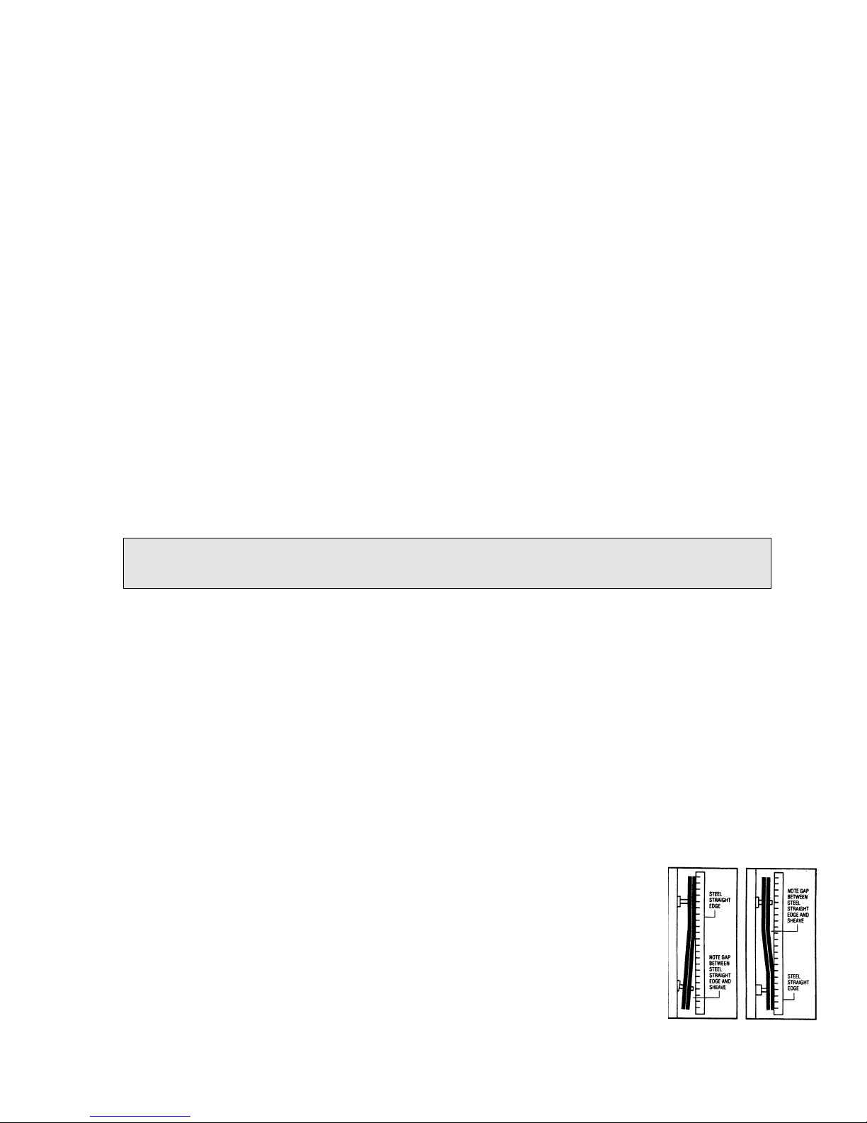
5. The two most common causes of misalignment are shown in the
Figure 1 and Figure 2 to the right.
a). The engine drive shaft and the blade shaft are not parallel.
b). The pulleys are not located properly on the shafts.
6. To check alignment, all you need is a steel straight edge.
22
FIGURE 1
FIGURE 2
Page 23

7. Line up the straight edge along the outside face of both pulleys as shown in the
drawing.
8. Misalignment will show up as a gap between the pulley face and the
straight edge.
9. Make sure that the width of the outside land (Area between the belt and the edge
of the pulley) is equal on both pulleys.
D. Depth Control
The cutting depth is controlled by a chrome turn handle. It is located next to the
push handle base, easily accessible from the rear of the saw. The handle must first
be unlocked before it can be turned. It is locked by a black knob located on the
operator’s left side of the hand wheel near the base of the handle. This knob must
be turned counter-clockwise to unlock the handle. Once unlocked rotating the
handle clockwise will lower the cutting blade. Rotating it counter-clockwise will raise
the cutting blade. When the proper cutting depth is achieved by reading the depth
gauge, relock the turn handle to ensure a constant cutting depth throughout the cut.
The depth gauge can be found further down the shaft of the turn handle. This gauge
will already be preset for an Ø10" blade, but it still must be calibrated by the user
since blade diameters may vary. When using an Ø8" blade, the gauge must be
readjusted from an Ø10" blade to an Ø8" blade. Simply loosen the black knob found
near the collar of the gauge and slide it accordingly to achieve the proper reading.
The collar used to support the turn handle's screw should be checked after each use
to make sure it is lubricated and turning freely. If more lubricant must be added,
NLGI #2, aluminum complex type grease is recommended.
E. Cleaning
It is recommended to wipe all concrete dust off of the unit after each use. Once a
month blow the motor and motor fan off with compressed air. Do not pressure wash
the motor, switch boxes, electrical connects, bearings, belts, or bellows as damage
by occur. Damage caused by pressure washing is not covered under any warranty.
23
Page 24
IV. PARTS LIST SECTION
A. Ordering Information
1. List model number and serial number of machine.
2. List part number and serial number of part not the item number.
3. Wherever alternate parts are shown due to product improvement, inspect the
part you have and provide additional description as necessary.
4. Specify mode of shipping desired, such as, parcel post, truck, U.P.S., best way,
etc.
For the nearest Clipper distributor call 1-800-554-8003
Common Replacement Parts
Description Part Number
WRENCH UNIVERSAL 233041
LOOSE COLLAR 241081
NUT 5/8-11 UNC HEX LEFT HAND THREAD 241083
KNOB W/THREADED STUD M6 X 15 1.0 241029
KNOB W/THREADED HOLE M6 X 15 1.0 241032
KNOB W/THREADED HOLE M10 X 1.5 X 50mm DIA 241061
VACUUM SHORUD PLATE GC25E UP 241161
TIGHT COLLAR 241082
GUARD BLADE 241001
BLADE SHAFT 241016
BEARING RADIAL 6204-RS 212142
HAND WHEEL 241023
BELLOWS 241026
CUTTING HEAD FLANGE 241037
POINTER WELDMENT 241085
SWITCH EMERGENCY STOP 241059
WHEEL 75X28X8mm 241086
WHEEL W/BEARING 241044
SHROUD CLAMP GC25E UP 241162
VACUUM SHOURD GC25E UP 241163
NOTE: All Parts Are Sold As Individual (each) Unless Noted Otherwise
Blades Use Only Norton Diamond Blades. Contact your local Norton Clipper
Distributor or Norton Clipper at 1-800-554-8003 for the best blade for the application.
24
Page 25
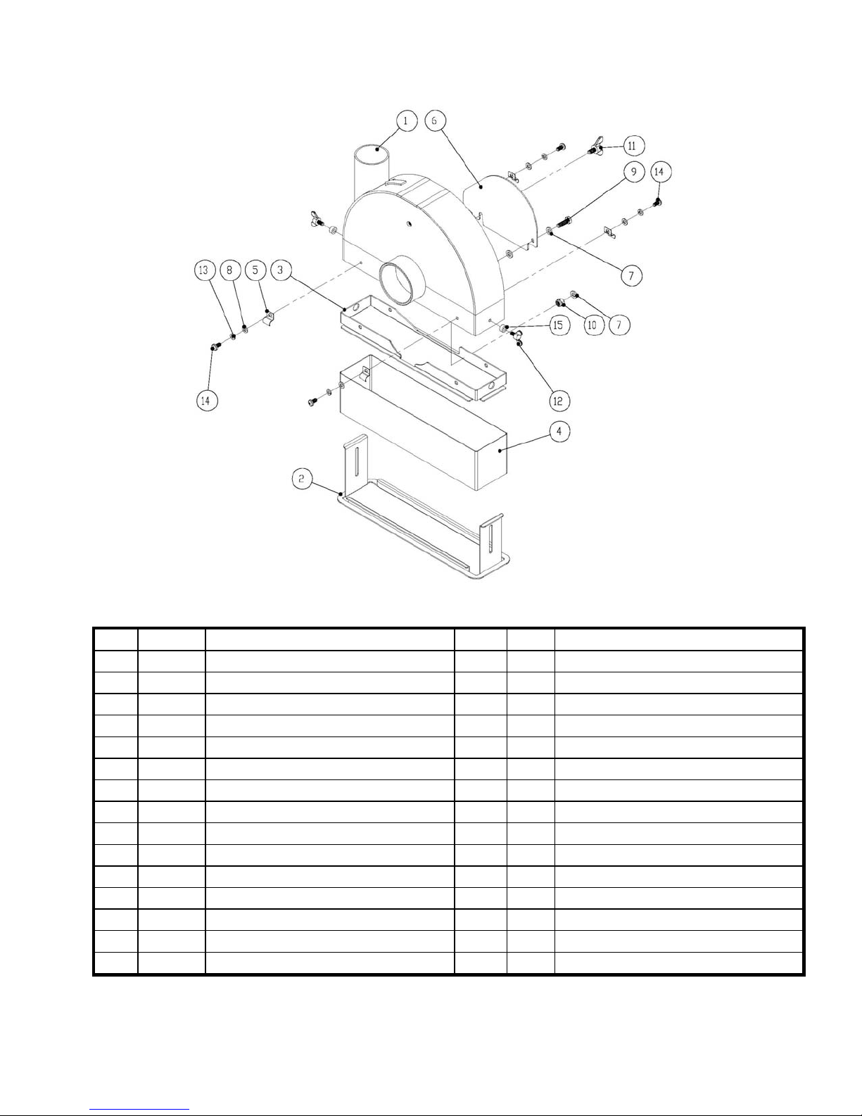
Blade Guard Assembly GC25E UP
Item Part No Description QTY Type NOTES
1 241160 BLADE GUARD WELDMENT GC25E UP 1 S Blade Guard Only GC25E UP ONLY
2 241161 VACUUM SHORUD PLATE GC25E UP 1 W GC25E UP Only
3 241162 SHROUD CLAMP GC25E UP 1 W GC25E UP Only
4 241163 VACUUM SHOURD GC25E UP 1 W GC25E UP Only
5 241164 CLIP RETAINING 6MM 4 W Sold As Each
6 241002 BLADE SHAFT VENT COVER 1 S
7 27539 WASHER M6 DIN 125 FLAT 3 S Sold As Each
8 235065 WASHER M5 DIN125 FLAT 4 S Sold As Each
9 235048 SCR M6 X 16 1.0 DIN933 8.8 1 S
10 235136 NUT M6 DIN985 LOCK 1 S
11 241003 SCR THUMB M6 X 12 1.0 1 S
12 241165 SCR THUMB M5 X 10 0.8 WING 2 S Sold As Each
13 502088 WASHER M5 LOCK DIN127B 4 S Sold As Each
14 241166 SCR M5 X 10 0.8 PAN HEAD DIN7985 4 S Sold As Each
15 241167 SPACER 10 OD X 5.6 ID X 5 L 2 S Sold As Each
25
Page 26
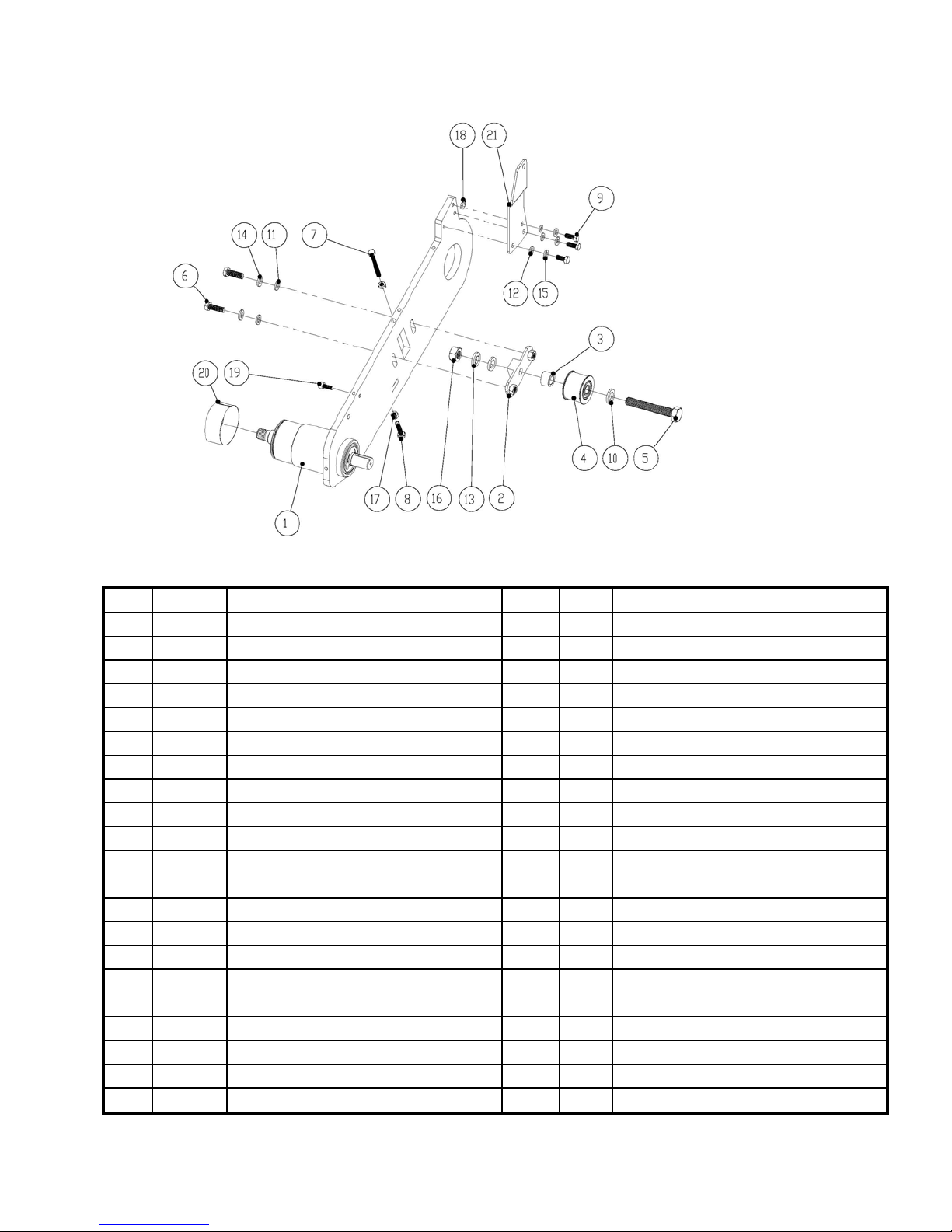
Cutting Head Assembly GC25E UP
Item Part No Description QTY Type NOTES
1 241151 CUTTING HEAD W/BEARING GC25E UP 1 S GC25E UP Only
2 241006 PULLEY IDLER TENSION ADJUSTER 1 S
3 241007 SPACER INDLER 1 S
4 241008 PULLEY IDLER ASSEMBLY 1 W
5 241010 SCR M12 x 80 1.75 DIN933 1 S
6 300323 SCR M8 X 25 1.25 DIN933 HHC FULL THD 2 S Sold As Each
7 241011 SCR M6 X 55 1.0 DIN931 1 S
8 241012 SCR M6 X 30 1.0 DIN933 HEX HEAD CAP 1 S Sold As Each
9 232113 SCR M6 X 16 1.0 DIN912 SHCS 3 S Sold As Each
10 27505 WASHER M12 DIN125 FLAT 2 S Sold As Each
11 232110 WASHER M8 DIN125 FLAT 2 S Sold As Each
12 27539 WASHER M6 DIN 125 FLAT 3 S Sold As Each
13 27017 NUT LOCK M12 1.75 DIN985 1 S
14 300245 WASHER LOCK M8 DIN127 2 S Sold As Each
15 300279 WASHER LOCK M6 DIN127B 3 S Sold As Each
16 27007 NUT M12 1.75 HEX DIN934 1 S
17 300833 NUT M6 1.0 DIN934 HEX 2 S Sold As Each
18 241009 FIT GREASE M6 X 14 1.0 1 S
19 232113 SCR M6 X 16 1.0 DIN912 SHCS 1 S
20 241014 BUSHING BLADE GUARD 1 W
21 241100 BRACKET DEPTH CNTRL MOUNT 1 S
26
Page 27
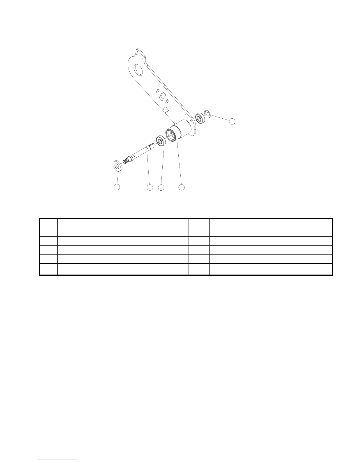
5
3
2
4
1
Blade Shaft Assembly GC25E UP
Item Part No Description QTY Type NOTES
1 241150 CUTTING HEAD GC25E UP 1 S GC25E UP Only
2 241016 BLADE SHAFT 1 S
3 241017 BEARING COVER BLADE SHAFT 1 S
4 212142 BEARING RADIAL 20MM .787B 2 W Sold As Each
5 241018
RETAINING RING E-STYLE 19mm X 1.8mm
DIN6799 1 S
27
Page 28
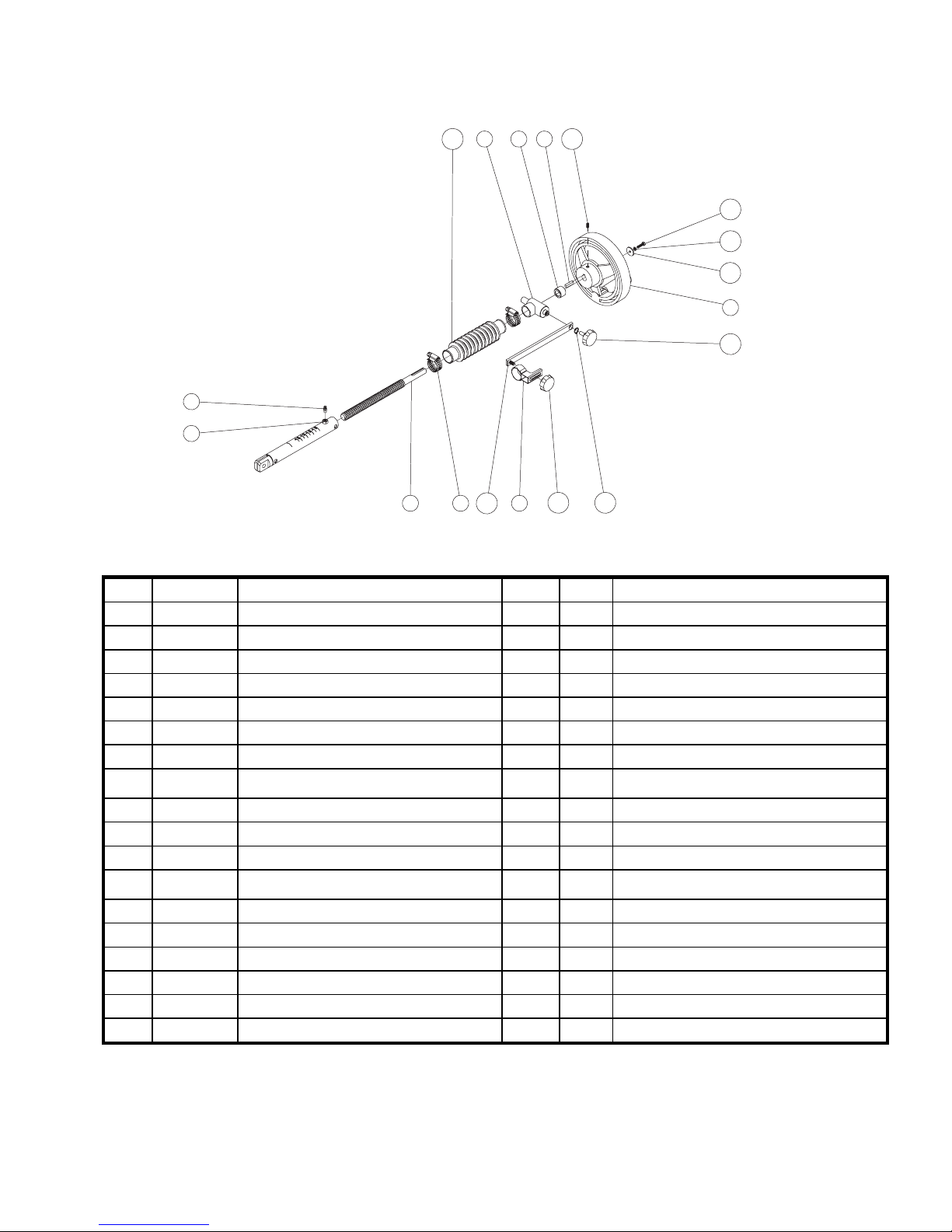
10945711
16
15
14
6
13
2
1
17
3
8
18
12
Depth Control Assembly GC25E UP
Item Part No Description QTY Type NOTES
1 241090 DEPTH TUBE 1 S
2 241019 FIT GREASE ZERK M6 X 1.0 1 S
3 241020 SCR DEPTH CONTROL 1 S
4 241021 DEPTH CONTROL MOUNT 1 S
5 241022 SPACER HAND WHEEL 1 S
6 241023 HAND WHEEL 1 S
7 9201074 KEY 3/16X3/4 1 S
8 241024 CLAMP HOSE 13/16" TO 1-3/4" X 1/2"W
WORM TYPE
9 241025 DEPTH GAUGE POINTER 1 S
10 241026 BELLOWS 1 W
11 241027 SCR M5 X 10 0.8 DIN916 SET CUP POINT 1 S
12 241028 RETAINING RING C-STYLE 10mm X
1.0mm DIN471
13 241029 KNOB W/THREADED STUD M6 X 15 1.0 1 S
14 241089 WASHER M4 X 19mm X 2mm 1 S
15 241030 WASHER LOCK M4 DIN127 1 S
16 235057 SCR M4 X 16 0.7 DIN933 1 S
17 241031 DEPTH CONTROL POINTER BAR 1 S
18 241032 KNOB W/THREADED HOLE M6 X 15 1.0 1 S
2 S Sold As Each
1 S
28
Page 29
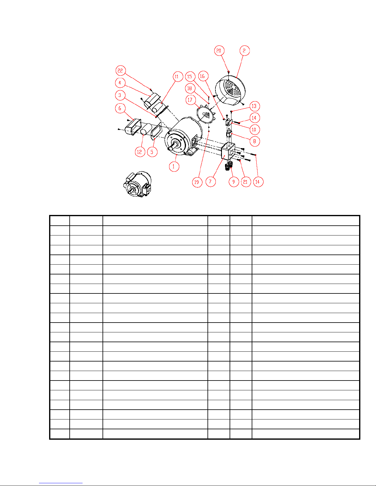
Motor Assembly GC25E UP
Item Part No Description Qty Type Notes
1 241112 MOT 2.5HP 115-230v/60/1 1 S
2 241113 COVER FAN 1 S
3 241114 GASKET RUN CAPACITOR COVER 1 W
4 241115 COVER RUN CAPACITOR 1 S
5 241116 GASKET START CAPACITOR COVER 1 W
6 241117 COVER START CAPACITOR 1 S
7 241118 BOX VOLTAGE CHANGE SWITCH 1 S
8 241119 TOGGLE SWITCH 1 W
9 241120 CABLE GLAND PG-11 2 S
10 241121 GUARD SWITCH 1 S
11 241122 CAPACITOR RUN 1 W
12 241123 CAPACITOR START 1 W
13 241124 SCR 10-24 X 3/8 PHILLIPS ROUND HEAD 2 S
14 241125 SCR M5 X 40 0.8 DIN7985 PH PHILLIPS 3 S
15 241126 SCR M5 X 40 0.8 DIN7985 PH PHILLIPS 1 S
16 241127 NUT M5 0.8 LOCK DIN985 1 S
17 241128 FAN 1 S
18 235104 WASHER M4 DIN125 FLAT 2 S
19 241129 NUT M4 0.7 DIN934 1 S
20 241124 SCR 10-24 X 3/8 PHILLIPS ROUND HEAD 3 S
21 241125 SCR M6 X 16 1.0 DIN7985 PH PHILLIPS 4 S
22 241126 SCR 10-24 X 1/4 PHILLIPS ROUND HEAD 4 S
Complete Motor (Items 2 to 21)
29
Page 30
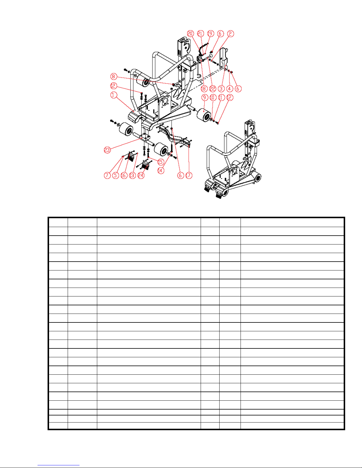
Frame Assembly
Item Part No Description Qty Type Notes
1 241101 FRAME GC25E/GC25E UO 1 S
2 241040 SCR M8 X 65 1.25 DIN931 HEX HEAD CAP 1 S
3 241039 REAR POINTER 1 S
4 232110 WASHER M8 DIN125 FLAT 7 S
5 235104 WASHER M4 DIN125 FLAT 17 S
6 241041 NUT M8 1.25 LOCK DIN985 4 S
7 241042 NUT M4 0.7 LOCK DIN985 8 S
8 241058 GROMMET 1 S
9 241044 WHEEL W/BEARING 4 W
10 241045 WASHER M8 X 24MM OD DIN9021B 4 S
11 300245 WASHER LOCK M8 DIN127 8 S
12 235013 SCR M8 X 20 1.25 DIN933 HEX HEAD CAP 6 S
13 235103 SCR M4 X 12 0.7 DIN933 HEX HEAD CAP 8 S
14 241040 SCR M8 X 65 1.25 DIN931 HEX HEAD CAP 1 S
15 241047 SCR M8 X 35 1.25 SOCKET HEAD CAP 2 S
16 241048 BRUSH WHEEL OPERATOR'S RIGHT 1 W
17 241050 SQUEEGEE ASSEMBLY ONLY 1 W
18 241102 POWER CABLE SUPENSION ARM 1 S
19 235099 SCR M4 X 8 0.7 DIN966 PHILIPS 1 S
20 241056 CHAIN FOR QUICKRELEASE PIN 9" LONG 1 S
21 241030 WASHER LOCK M4 DIN127 1 S
22 241092 PIN QUICKRELEASE 5/16" X 2" GRP LENGTH 1 S
23 241046 FRONT AXLE 1 S
24 241049 BRUSH WHEEL OPERATOR'S LEFT 1 W
Frame Only
30
Page 31
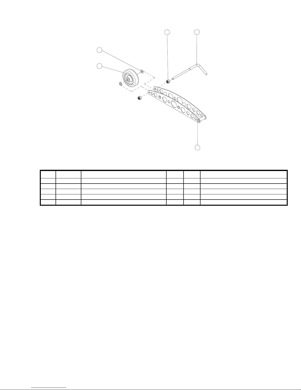
5
4
2
3
1
Front Pointer Assembly GC25E UP
Item Part No Description QTY Type NOTES
1 241085 POINTER WELDMENT 1 S Weldment Only, NO Components
2 241086 WHEEL 75X28X8mm 1 W
3 241087 FRONT POINTER ROD 1 S Sold As Each
4 232110 WASHER M8 DIN125 FLAT 2 S Sold As Each
5 241041 NUT M8 1.25 LOCK DIN985 2 S Sold As Each
31
Page 32
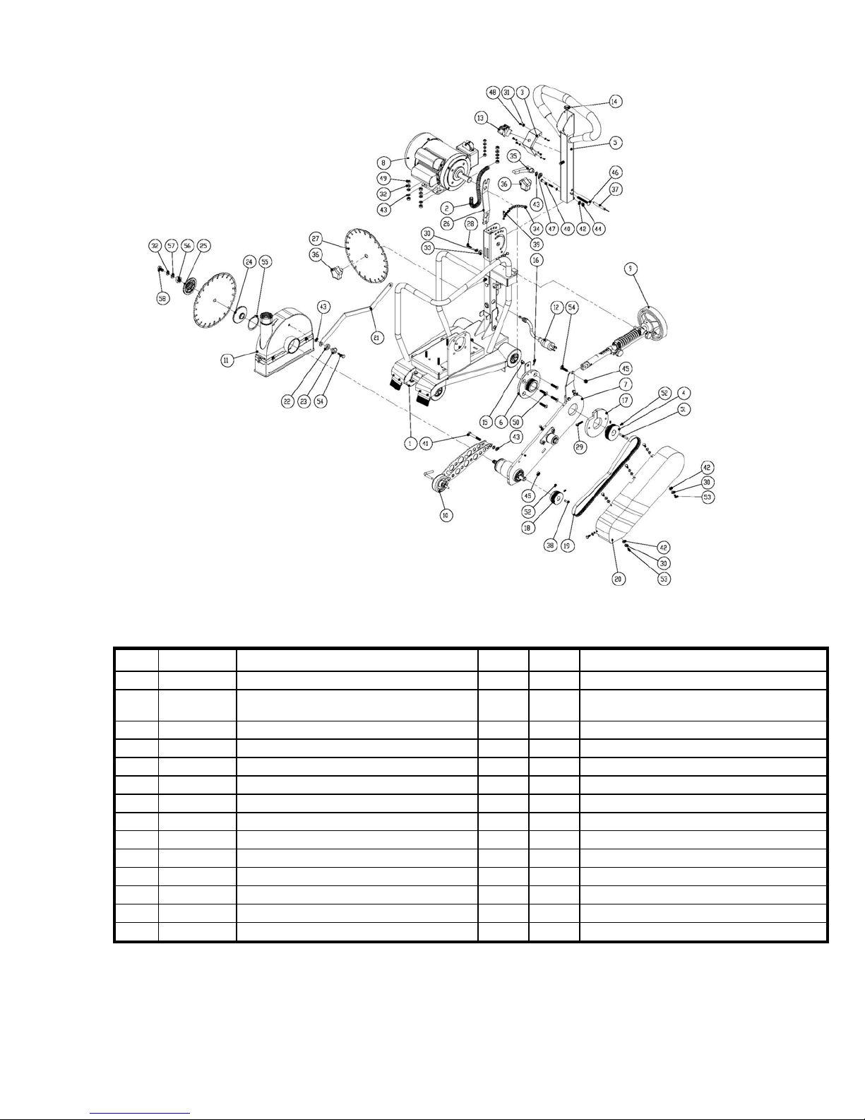
Main Frame Assembly GC25E UP
Item Part No Description QTY Type NOTES
1 241152 FRAME ASSY GC25E/GC25E UP 1 S Includes Wheels – NO additional Components
2 241109 CONDUIT 14.5MM OD X 10MM ID
FLEXIBLE
3 241105 PANEL SWITCH 1 S
4 241107 PULLEY 70MM X 24MM 6G J SECTION 1 W
5 241052 HANDLE BAR 1 S
6 241110 COLLAR ASSMELBY 1 S
7 241153 CUTTING HEAD ASSY GC25E UP 1 S GC25E UP ONLY
8 241112 MOT 2.5HP 115/230/60 1 S
9 241084 DEPTH CONTROL ASSY 1 S
10 241073 FRONT POINTER ASSY 1 S
11 241154 BLADE GUARD ASSY GC25E UP 1 S GC25E UP ONLY
12 241111 PLUG NEMA L5-15 115V 15A TWIST LOCK 1 S
13 241104 SWITCH TOGGLE 125V/15A W/SHIELD 1 W
14 241058 GROMMENT 20 OD X 16 ID X 2MM 1 W
1 S
Main Frame Assembly GC25E UP
32
Page 33
Item Part No Description QTY Type NOTES
15 241064 PIN CLEVIS 3/8"OD X 1/2" LONG 1 S
16 241065 PIN 0.073OD X 1-7/16" (3/8" PIN) HAIR
COTTER
17 241067 COLLAR LOCK 1 S
18 241071 PULLEY 56.5MM D X 3/4B 6G J SECTION 1 W
19 241155 BELT 380J6 J SECTION 6 GROOVE 1 W “J” Section Belt, Six (6) Grooves 380mm Long
20 241156 BELT GUARD GC25E UP 1 S GC25E UP ONLY
21 241157 ARM STAY LEVEL GC25E UP 1 S GC25E UP ONLY
22 241079 SPACER M14 1 S
23 241080 CAM STAY LEVEL 1 S
24 241081 LOOSE COLLAR 1 S
25 241082 TIGHT COLLAR 1 S
26 233041 WRENCH UNIVERSAL 1 S
27 -NA- BLADE 1 W Contact Customer Service
28 241069 SCR M6 X 20 1.0 DIN912 SOCKET HD HEX 1 S
29 241068 SCR M6 X 30 1.0 DIN912 SOCKET HD HEX 1 S
30 300279 WASHER LOCK M6 DIN127B 7 S Sold As Each
31 241030 WASHER M4 LOCK DIN127B 6 S Sold As Each
32 300245 WASHER LOCK M8 DIN127 4 S Sold As Each
33 27539 WASHER M6 DIN 125 FLAT 1 S
34 241056 CHAIN 1.5 D X 22 L 1 S
35 241091 KNOB M8 X 1.25 ADJUSTABLE 1 S
36 241061 KNOB W/THREADED HOLE M10x1.5x50 2 S Sold As Each
37 241092 PIN QUICKRELEASE 5/16" X 2" GRIP L 1 S
38 9201074 KEY 3/16x3/4 1 S
39 241057 SCR M4 X 20 1.59 PAN HEAD SELF TAP 1 S
40 241158 SCR M6 X 18 1.0 DIN933 HEX HEAD CAP 1 S
41 360146 SCR M8 X 60 1.25 DIN933 HHC FULL THD 1 S
42 27539 WASHER M6 DIN 125 FLAT 8 S Sold As Each
43 232110 WASHER M8 DIN125 FLAT 12 S Sold As Each
44 235136 NUT M6 DIN985 LOCK 1 S
45 241041 NUT M8 1.25 LOCK DIN985 2 S
46 241054 SCR 5/16-18 UNC X 2-1/2" CARRIAGE 1 S
47 241055 WASHER 3/8 WAVE 1 S
48 235099 SCR M4 X 8 DIN966 PHILIPS 6 S Sold As Each
49 228116 NUT M8 1.25 DIN439B HEX 8 S Sold As Each
50 241106 SCR M8 X 35 1.25 SHCS DIN7991 4 S Sold As Each
51 241108 KEY 5X5X45MM 1 S
52 241027 SCR M5 X 10 0.8 DIN916 CUP POINT SET 4 S Sold As Each
53 241062 SCR M6 X 14 1.0 DIN933 6 S Sold As Each
54 241063 SCR M8 X 30 1.25 DIN933 HEX HEAD CAP 2 S
55 241076 RING 60MM EXTERNAL C-CLIP 1 S
56 241083 NUT 5/8-11 UNC HEX LEFT HAND THR 1 S
57 241159 WASHER M8 THICK FLAT 1 S
58 8041026 SCR 5/16-18 X 3/4 HEXHDCP 1 S
1 S
33
Page 34

Saint-Gobain Abrasives
2770 West Washington
Stephenville, TX 76401
Phone: 800-554-8003
Fax: 800-443-1092
34
 Loading...