

Page 1
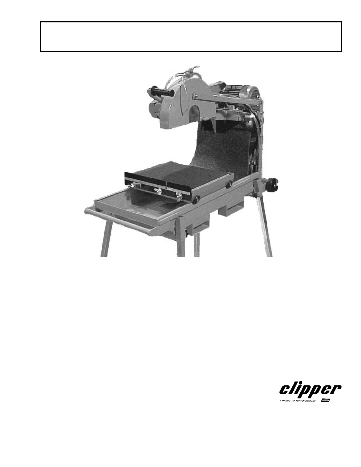
OWNERS MANUAL
COMPACT MASONRY SAW
MODELS
BBC157
BBC207
BBC547
FORM <<7506 rev 2/2006
Page 2

WARRANTY
Norton warrants all products manufactured by it against defects in workmanship
or materials for a period of one (1) year from the date of shipment to the
customer.
The responsibility of Norton under this warranty is limited to replacement or
repair of defective parts at Norton's Gainesville, Georgia factory, or at a point
designated by it, of such part as shall appear to us upon inspection at such point,
to have been defective in material or workmanship, with expense for
transportation borne by the customer.
In no event shall Norton be liable for consequential or incidental damages arising
out of the failure of any product to operate properly.
Integral units such as gasoline engines, electric motors, batteries, tires,
transmissions, etc., are excluded from this warranty and are subject to the
prime manufacturer's warranty.
This warranty is in lieu of all other warranties, expressed or implied, and all such
other warranties are hereby disclaimed.
Important: Before placing equipment in operation, record the following
information.
MODEL:_________ SERIAL NO.___________
PURCHASE FROM: _____________________
ADDRESS: ____________________________
CITY_______ STATE ______ ZIP ________
TELEPHONE NO. ______________________
Before using this equipment, make sure that person using it
Read and understand the instructions in this owner’s manual.
2
Page 3

BBC 157/207/547
OWNER'S MANUAL
I. Preparation
A. Safety Precautions 4-6
B. Assembly 7-12
C. Specifications 13
D. Electrical Connections 14
E. Wiring Diagram 15
F. Gasoline Engine 16
II. Operation
A. How to mount Blade 17
B. How To Use "Step Cutting"
with abrasive blades
C. How To Use "Jam Cutting"
And "Step Cutting" With
Diamond Blades.
D. Dry Cutting 20
E. Wet Cutting 20
III. Maintenance
A. V-Belts 20
B. Electric Motor 21
Electric Motor Warranty/Service 21
C. Gasoline Engine 21
Gasoline Engine Warranty/Service 21
D. Blade Shaft Bearings 21-22
E. Water Pump 22
IV. Parts List Section
A. Ordering Information 23
B. Parts List 24-32
C. Baldor Service Policy 33
D. Honda Service Policy 34
CONTENTS PAGE
18
19
Safety Alert Symbol: Information Following This Symbol Is Very Important.
Use Only Norton Clipper Diamond Blades
Read Owners Manual Before Use
3
Page 4
I. PREPARATION
A. Safety Precautions
Important! The following safety precautions must always be observed.
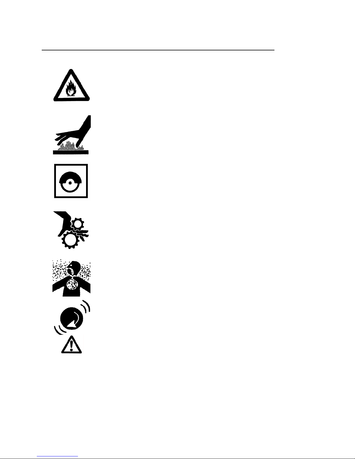
Hazard Symbols
Fuel (gasoline) is extremely flammable and its vapors can explode if ignited.
Store gasoline only in approved containers, in well-ventilated, unoccupied
approved areas, and away from sparks or flames. Do not fill the fuel tank
while the engine is hot or running. Do not start the engine near spilled fuel.
Never use the fuel as a cleaning agent
Engine components can get extremely hot from operation. To prevent burns,
do not touch the engine or related parts while the engine is running or
immediately after it is turned off. Never operate the engine with any heat
shields or guards removed.
Keep all guards in place when operating any piece of equipment
Keep hands, feet, hair, and clothing away from all rotating parts
Lethal Exhaust Gas use only in well ventilated areas. Engine exhaust gases
contain poisonous carbon monoxide, which is odorless, colorless, and can
cause death if inhaled. Avoid inhaling exhaust fumes, and never run the
engine in a closed building or confined area
Never tamper with the governor components of settings to increase the
maximum speed. Severe personal injury and damage to the engine or
equipment can result if operated at speed above maximum. Always obey the
maximum speed rating of blade.
DO NOT LIFT THE SAW BY THE HANDLE BARS
4
Page 5

Dust and Silica Warning
Grinding/cutting/drilling of masonry, concrete, metal and other materials can generate dust,
mists and fumes containing chemicals known to cause serious or fatal injury or illness, such as
respiratory disease, cancer, birth defects or other reproductive harm. If you are unfamiliar with
the risks associated with the particular process and/or material being cut or the composition of
the tool being used, review the material safety data sheet and/or consult your employer, the
material manufacturer/supplier, governmental agencies such as OSHA and NIOSH and other
sources on hazardous materials and make certain to comply with all product warnings and
instructions for the safe and effective use of the material being cut. California and some other
authorities, for instance, have published lists of substances known to cause cancer,
reproductive toxicity, or other harmful effects.
Control dust, mist and fumes at the source where possible. In this regard use good work
practices and follow the recommendations of the manufacturer/supplier, OSHA/NIOSH, and
occupational and trade associations. Water should be used for dust suppression when wet
cutting is feasible. When the hazards from inhalation of dust, mists and fumes cannot be
eliminated through engineering controls such as either vacuum and/or water mist, the operator
and any bystanders should always wear a respirator approved by NIOSH/MSHA for the
material being cut.
Use Approved:
Eye Protection Hearing
Protection
Respiratory
Protection
5
Head Protection
Page 6
1. Before mounting any blade on the saw, the blade should be inspected for any damage
which might have occurred during shipment, handling or previous use.
2. The blade collars and arbors should be cleaned and examined for damage before
mounting the blade.
3. The blade must be properly fitted over the arbor with the drive pin on the outside
collar projecting through the drive pinhole on the blade and inside collar.
4. The blade shaft nut, which is a left-hand thread nut, must be tightened securely
against the outside blade shaft collar.
5. The blade must be operated within the specified maximum operating speed listed on
the blade.
6. Turn water control valve to full to provide adequate coolant (4 to 6 gallons per
minute) for diamond blades and wet cutting abrasive blades. Insufficient coolant
could result in severe blade breakage or diamond segment separation.
7. The blade guard must be in place with the nose guard down and locked when the saw
is running.
8. The operator should wear safety glasses and any other appropriate safety equipment.
9. When starting the saw, the operator should stand away and to the side of the blade.
10. If for any reason the saw should stall in the cut, raise the blade out of the cut. Check
the outside blade shaft collar and nut for tightness. Inspect the blade for damage
before restarting the saw. Use caution when resuming a cut. Be certain that the
blade is in alignment with the previous cut.
11. During cutting operations, do not exert excess side pressure on the handles as a
method of steering. Do not force the blade into the cut by lowering the blade too fast
or by pushing the saw too fast.
You Are Responsible For Your Safety!!!
6
Page 7
I. PREPARATION
B. Assembly
The compact Masonry saws are shipped completely assembled and ready for use except
for diamond blade, gasoline, oil, and Head Locking Bar. Inspect the saw for shipping
damage. If any damage is found, contact the shipper immediately and file a freight claim.
The Norton Company is not responsible for any freight-related damages.
Remove the saw from the pallet.
Items Included with the saw:
Item Part Number QTY
Head Locking Handle 82738 1
Depth Limit Assembly 1
Legs Set of 4 75817 1
Conveyor Cart Assembly 83754 1
Guide-A-Cut Assembly 83892
Water Curtain Assembly 75128 1
Wrench 19 mm 70807 1
Wrench 22mm 72143 1
Water Pump Assembly 72305 1
14” Genuine Norton Diamond Blade for Brick And Block 7499 1
Head Locking Handle:
Remove the Head Locking Screw from the machine (see Figure: Head Locking Screw
Removal). Replace the Head Locking Screw with the Head Locking Handle located in the
plastic bag of accessories (see Figure: Head Locking Handle Installation). Read and
understand the remaining sections of this Owners Manual.
The Head Locking Handle is used to lock the cutting head at a set position or depth of cut.
The Head Locking Screw is only used to hold the Cutting Head of the machine in place at
the Norton Company Factory.
Do not install the blade until it is time to use the saw!
ANSI regulations prohibit the transportation of any concrete
saw with the blade installed!
7
Page 8
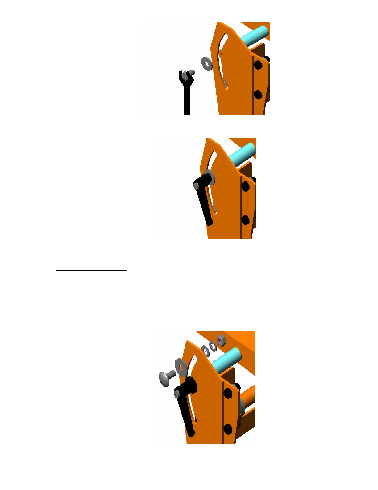
Figure 1: Head Locking Screw Removal
Figure 2: Head Locking Handle Installation
Depth Limiting Bolt:
Remove the 12mm Carriage Bolt, 12mm Large Flat Washer (DIN9021), 12mm Flat
Washer, 12mm Lock Washer, and 12mm Nut from the plastic Bag. Place the 12mm Large
Washer over the 12mm Carriage Bolt. Slide the 12mm Carriage thru the Head Locking
handle Slot either above the Head Locking Handle (to limit the depth of cut) or below the
Head Locking Handle (to limit the tilt angle of the Cutting Head) and attach the 12mm Flat
Washer, 12mm Lock Washer, and 12mm Nut as show in Figure 3: Depth Limiting Bolt
Assembly.
Figure 3: Depth Limiting Bolt Assembly
8
Page 9
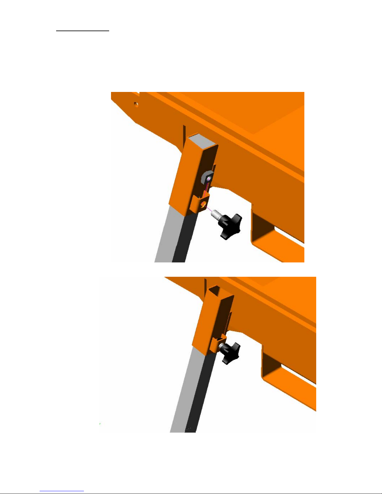
Leg Assembly:
Remove the four (4) Legs from the Saw Water Pan, and the four (4) Plastic Handle Knobs
and four (4) Square Nuts from the plastic bag. Place one (1) Square Nut into each of the
Nut Retaining Brackets located on each of the Leg Holders. Attach one (1) Plastic Knob to
each of the Square Nuts as shown in Figure 4: Plastic Knob Attachment. NOTE: Do not
tighten Plastic Knobs at this time. Place one (1) Leg into each of the Leg Holders and
tighten the Plastic Knobs see Figure 5: Leg Attachment.
Figure 4: Plastic Knob Attachment
Figure 5: Leg Attachment
9
Page 10
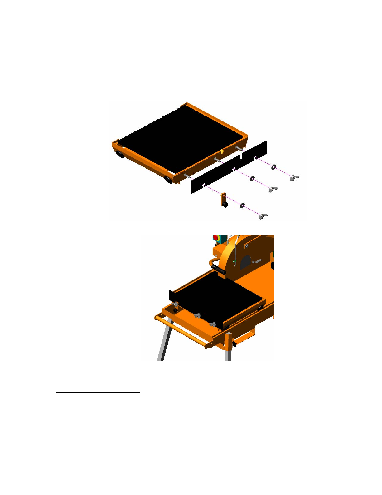
Conveyor Cart Assembly:
Remove the Conveyor Cart and Back Stop from the Saws Water Pan, and the Wing Nuts,
Carriage Bolts, Washers, and Cart Stop from the plastic bag. Slide one (1) Carriage Bolt
thru each of the three (3) Square Holes located on the front of the Conveyor Cart. Slide the
Back Stop Over each of the Carriage Bolts. Slide the Stop Assembly over the Carriage
Bolt Located on the Left front of the Conveyor Cart NOTE: The Rubber Stop will faces
away from the Conveyor Cart. Attach one (1) Washer and one (1) Wing Nut to each
Carriage Bolt and Tighten. See Figure 6: Back Stop Assembly. Place the Conveyor Cart
on the Machine see Figure 7: Conveyor Cart Installation.
Figure 6: Back Stop Assembly
Figure 7: Conveyor Cart Installation
Guide-A-Cut Assembly:
Attach the Guide-A-Cut to the Conveyor Cart by adjusting the Wing Bolt until the Guide-ACut can slide over the Black Stop. The Guide-A-Cut will work as a Rip Guide that is
adjustable for 90° and 45° cuts. See Figure 8: Guide-A-Cut Assembly.
10
Page 11
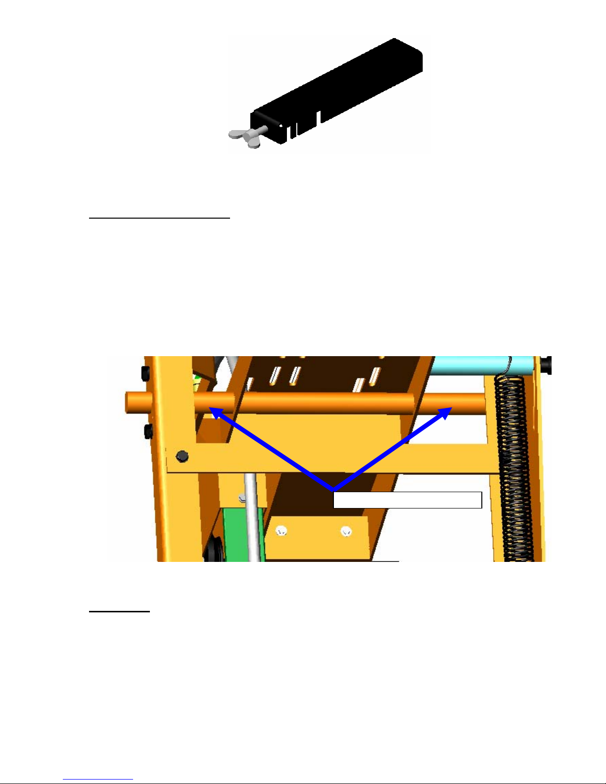
Figure 8: Guide-A-Cut Assembly
Water Curtain Assembly:
Remove the Water Curtain from the Saw Water Pan. Attach the Water Curtain Spring Clips
to the Pivoting Bar Located Under the Cutting Head. Note that the rough side of the Water
Curtain should face towards the front of the saw. The Water Curtain material is made is
designed to be easy to clean. To clean simply rinse the Water Curtain with water until
clean. The Water Curtain should be used when wet cutting to reduce the amount of debris
thrown from the blade and cutting surface. When dry cutting the Water Curtain can be
removed to allow the dust particles to drift away from the Saw Operator. See Figure 9:
Water Curtain Assembly.
Wrenches:
Remove the 19mm and 22mm Wrenches from the plastic bag. Place the Wrenches in the
Wrench Holder Slots located in the rear of the machine see Figure10: Wrench
Placement.
Attach Splash Guard Here
Figure 9: Splash Guard Assembly
11
Page 12
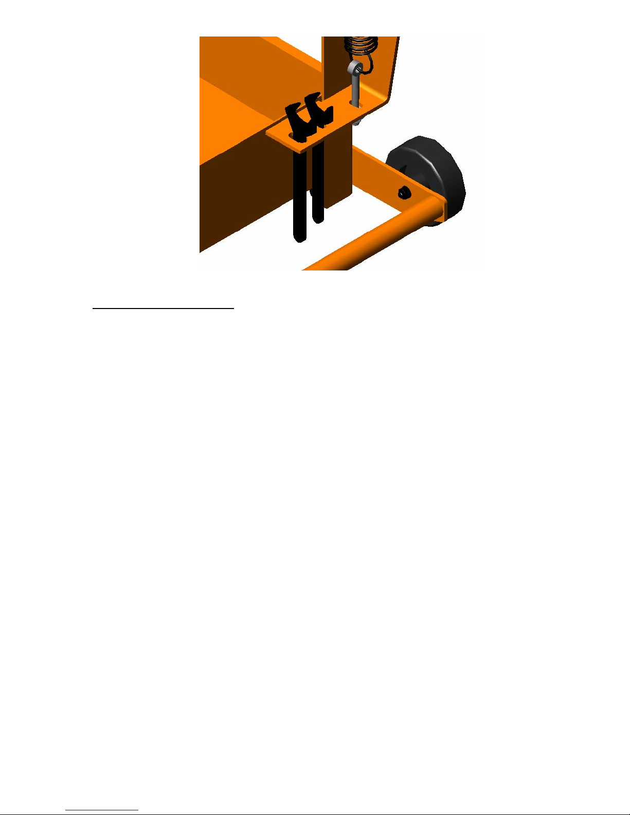
Figure 10: Wrench Placement
Water Pump Assembly:
The Water Pump requires no additional assembly.
12
Page 13

I. PREPARATION
C. BBC157/207/547 Series Masonry Saw Specifications
Dimensions/Weight
Length (Working) 60” (1524mm)
Width 24” (965mm)
Height (Electric) 34” (864mm)
Height (Gas) 38” (965mm)
Weight (Electric) Uncrated 250lbs (kg)
Weight (Gas) Uncrated 275lbs (kg)
Electric Motor
Motor Mfg. Baldor
Motor Type TEFC, Thermal Protection
Motor Voltages 115-230 (Switch able) 60 Hz single Phase
Motor RPM 3450
BBC157 Horse Power 1-1/2 HP
BBC157 Amp Draw 13.4 Amp @ 115v, 6.7 Amp @ 230v
BBC207 Horse Power 2 HP
BBC207 Run Amp 16.8 Amp @115v, 8.4 Amp @ 230v
Engine
Engine Mfg. Honda
Model GX160
Spec No. GX160K1QXC9
Engine Type Single Cylinder 4 Cycle
Horse Power 5.5 hp (4.0 kW) @ 3,600 rpm
Max Torque 8 ft-lbs (11 Nm, 1.1 kg-m) @ 2,500 rpm
Cooling System Forced Air
Oil Capacity 0.6 liter (0.63 US qt)
Fuel Capacity 3.6 liter (0.95 US gal)
Fuel Type Unleaded Gasoline (86 pump octane)
Fuel Consumption 310 g/kWh (0.51 lb/Hp hr)
Low Oil Sensor Yes
Air Filtration Four Stage Cyclone
Characteristics
Max Blade
Depth of Cut 14” (356 mm) 5” (127 mm)
12” (305 mm) 4” (102 mm)
Arbor Bore 1” (25.4 mm)
Blade Shaft Locking Device Machined Into Flats Of Tight Collar
Blade Shaft Speed 2900 rpm
Depth Control Hand Feed With Return Spring
Depth Lock Standard
Number Of V-Belts 1
Blade Guard Type All Steel Construction
Stay Level Blade Guard Yes
Fork Lift Brackets Built In
Rolling Wheels Standard
Water Pump Standard, Mechanically Belt Driven
Sound pressure
Sound power
1) The sound measures have been made following pr EN 12638, Annex A; 2)“ Floor sawing, grooving and milling machines – Safety “
1
(Gasoline Engine) 88 db (A)
1
(Gasoline Engine) 105 db (A)
∅14” (356 mm)
13
Page 14
I. PREPARATION
D. Electrical Connections
Important-Before connecting the motor leads to the power supply be sure that the
voltage, cycles and phase shown on the nameplate of the motor correspond to the
available power supply.
Voltage Selection For Single Phase Motors
1-1/2 h.p. and 2 h.p. single phase masonry saw motors have a dual voltage capable. A 115volt or 230 volt power supply can be used. To change voltage simply move the voltage
change switch located on the front of the motor to the required voltage, no rewiring is required.
Wherever possible, use 230-volt power supply for best operation.
Failure to run the motor on the proper voltage will damage the motor and is not
covered under warranty. Improperly wired motors are not covered under warranty.
Saws are wired for 115 Volt from the factory!!!
Power Connections
Connect the power supply to the pigtail leads of the switch. Direct wiring connection is
preferred, but an extension cord with an electrical plug with 30-amp minimum capacity may be
used. A 30-amp circuit breaker is recommended. Connecting wires should be as short as
possible and in one piece. In no case should the connecting wires be longer than shown in the
following table for 1-1/2 and 2 h.p. Single-phase motors:
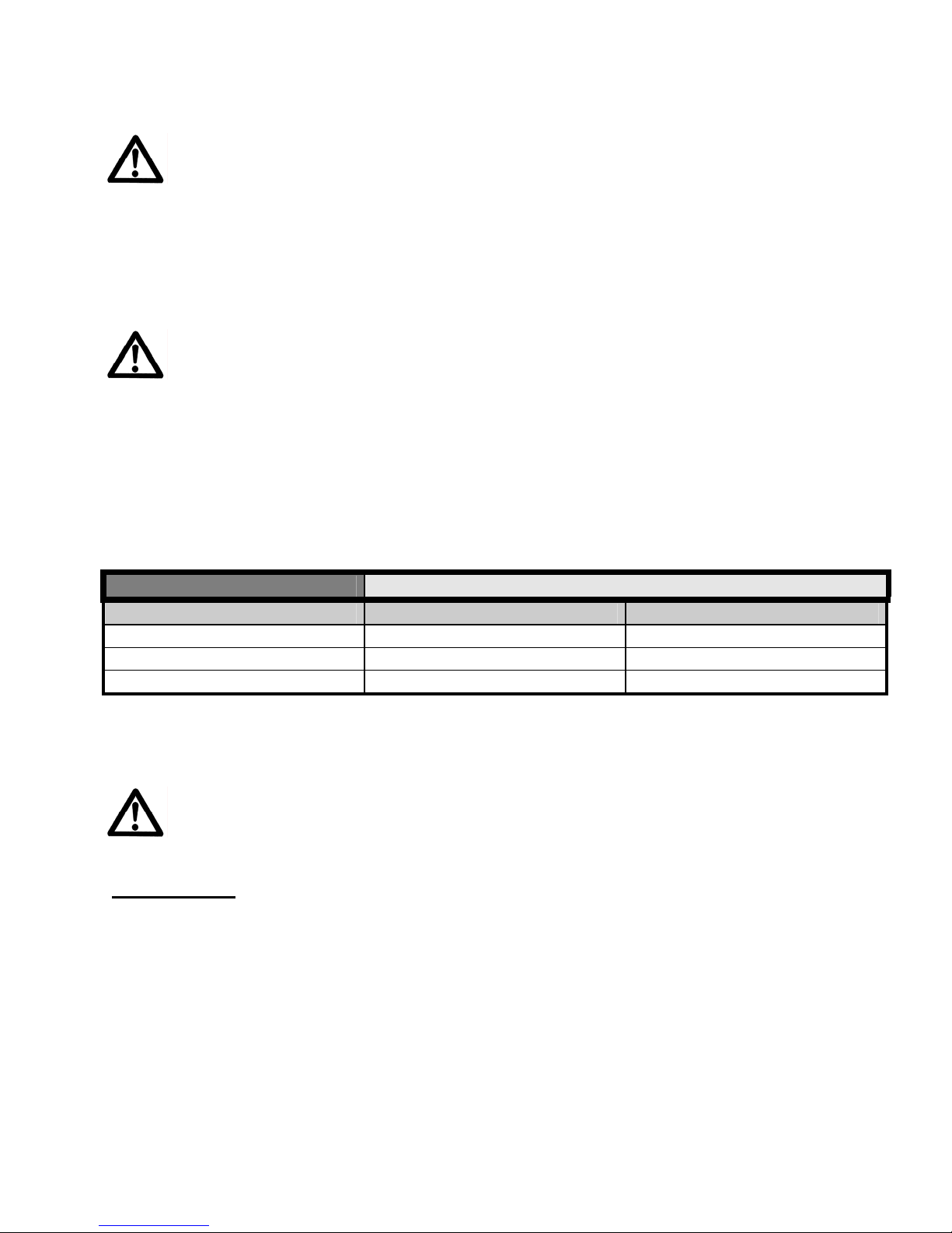
LENGTH OF WIRE
WIRE GAUGE 115 VOLT 230 VOLT
NUMBER 12 25 FEET 100 FEET
NUMBER 10 50 FEET 150 FEET
NUMBER 08 75 FEET 175 FEET
Caution-When wires that are too small gauge or too long are used, loss of power, over
heating, or possible damage to the motor will result.
Always use the proper wiring connectors that are UL/CSA approved to attach the
motor to the electrical supply. Any wiring hook ups should be made by qualified
personal and made to National Electrical Code and to any Local Codes.
Generators:
If a generator must be used, it must be of 8kW or larger. The generator must have a 30A
circuit and capable of providing a minimum of 8kW at the required voltage. Under size
generators will cause motor damage and is not covered under warranty.
14
Page 15
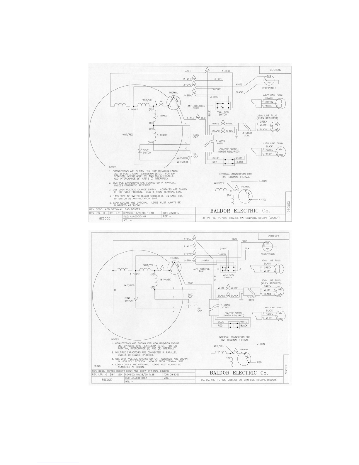
D. Wiring Diagram
Be sure to ground the saw properly before operating, such as a ground wire connection
provided by the power company.
Electrical Connections
115 Volt
230 Volt
For any Electric Motor service, warranty, or technical related questions please contact your nearest Baldor service center:
Baldor Electric Company
5711 R.S. Boreham, Jr. St.
P.O. Box 2400
Fort Smith, AR 72901
Phone: (501) 646-4711
Fax: (501) 648-5792
15
Page 16

I. PREPARATION
F. Gasoline Engine
Prior to attempting to operate the engine, read the information contained in the engine
owner's manual. An engine owner’s manual is supplied with every gasoline powered
concrete saw.
1. Check Oil: Add oil if low. Refer to the engine owner's manual for the recommended SAE
viscosity grades. Capacity of oil is 1.1 liters (1.16 US qt)
2. Check Fuel: Fill if low. Use only unleaded gasoline with a pump sticker octane rating of 86
or higher is recommended. Never use an oil and gasoline mixture!
3. Air Cleaner: Never run the engine without the air cleaner! Rapid engine wear will result
from contaminants being drawn through the carburetor and into the engine.
4. Engine Starting: Refer to the engine owner's manual for proper engine starting procedure.
Make sure that the Cutting Head Depth Limiting Bolt
Powered Saw should only rise to a maximum of nine (9) inches
above the surface of the Cutting Table
For any Engine service, warranty, or technical related questions please contact your nearest
Honda service centers:
Honda Power Equipment Group
4900 Marconi Dr.
Alpharetta, GA 30005-8847
Tel: (800) 426-7701 | Fax: (678) 339-2670
Web page: http://www.honda-engines.com/dis.htm
Assembly is in the bottom position. The head on the Gasoline
16
Page 17
II. OPERATION
A. Installing the Blade
1. For Gasoline powered machines disconnect the spark plug and for Electrical Powered
Machines disconnect from power source.
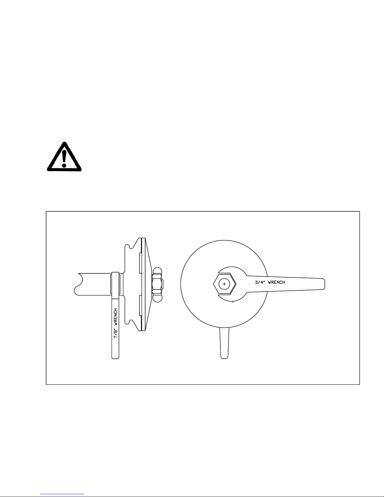
2. Remove the blade shaft nut, (Turn clockwise), and remove the outside collar.
3. Clean off any foreign particles on the clamping surfaces of both collars and on the mounting
surface of the blade.
4. Place the blade on the blade shaft.
Use only Norton Clipper Diamond Blades.
5. Slide the outside blade shaft collar onto the blade shaft.
6. Tighten the blade shaft nut (clockwise) securely against the outside collar by using the
Blade Shaft Wrench 19mm and Blade Shaft Flat Wrench 22mm as show in the figure below
7. Reconnect the spark plug or reconnect the electrical power.
Use Only Norton Clipper Diamond Blades
Figure 11: Blade Tightening
17
Page 18
II. OPERATION
B. How To Use " Step Cutting " With Abrasive Blades
Use "step cutting" without exception when cutting wet or dry with abrasive blades.
"Jam cutting", which is discussed and illustrated in the section following, is to be used only with
wet and dry cutting diamond blades.
1. Clamp and hold material firmly against the backstop on conveyor cart. Be certain
the material does not slip or rock during cutting operation, as this can bind blade,
causing excessive wear and fracture.
2. Move the conveyor cart near the blade, and pull down on the head until the blade is
lowered to a point where it will lightly contact the top of the material. Then start
"step cutting" - which means passing the material beneath the blade with rapid , (50
to 60 strokes per minute) full length strokes, taking a shallow cut (approximately 1/8"
deep ) on the forward, and also on the backward stroke. Complete each rapid stroke
backward and forward, by passing the material beyond the center of the blade before
starting the reverse movement of the cart. The harder the material, the more rapid
the forward and backward strokes.
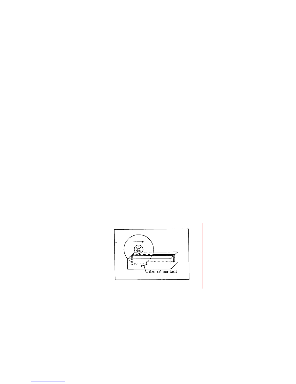
3. "Step cutting as can be seen in the sketch below, lessens the area of the blade
circumference in contact with the material, keeping the blade cool, running free, and
cutting at peak efficiency. Don't get the impression "step" cutting means slow
cutting - actually it is 6 times faster than trying to "force" the cut by strong-arming
the material through the blade. Forcing the blade through with a deep cut causes a
longer area of the blade circumference to be in contact with the material, causing
excessive friction heat to be generated, which then causes the blade to "smear" or
"load" with fused material particles and lose its sharp cutting surface. (Note: If
improper operation should cause an abrasive blade to "smear", make several cuts
through a soft brick to "dress” the blade back to good cutting performance.)
18
Page 19

II. OPERATION
C. How To Use "Jam Cutting" (Fixed Cutting) and "Step Cutting" With
Diamond Blades
In "Jam" cutting the head is locked in a fixed position and the material is pushed into it as
shown in the sketch at the bottom. "Jam" cutting with the head locked in a fixed position
usually provides greater efficiency.
1. To lock the head into position, tighten the lever nut at the back of the saw.
2. "Step" cutting with diamond blades is done by applying more pressure to the blade.
Unlike "step" cutting with abrasive blades, "step" cutting with diamond blades
requires only a few passes through the material.
3. In cutting, clamp the material securely and hold it firmly against the conveyor cart
backstop. If the material is allowed to slip, resulting seizure of the blade may bend
the diamond blade steel center or cause a ring section to be twisted off.
4. Do not force the material or bump into the blade. When nearing completion of the
cut, retard and slightly hold back the conveyor cart. If this is not done, the material
may be pulled into the blade so fast that excessive pressure on the rim may cause
warping or twisting of the rim section.
5. When a new diamond blade is broken in, make the first few cuts slowly until the
blade cuts freely and easily.
6. When the blade is cutting freely and easily. Use it! As long as it cuts satisfactorily do
not dress the diamond blade or remove it from the blade shaft.
7. After continuous cutting of extremely hard and dense materials, the blade may slow
down and it may be necessary to "dress" the cutting edge. To do this:
a. Use a rapid "step" cutting method for a few cuts - push the material back and
forth under the blade while it is cutting down. If this is not sufficient:
b. Make one or two cuts in a soft brick or light weight block.
However, "dressing" should be done as seldom as possible - because too much
"dressing" reduces blade life.
19
Page 20

II. OPERATION
D. How To Use Blockbuster Compact For Dry Cutting
1. Use a proper blade, which is marked for dry cutting.
2. Remove the water curtain.
3. Disconnect the water pump.
4. Use "step" cutting as explained previously when using abrasive blades.
5. Use "jam" or "step" cutting when using dry cutting diamond blades.
E. How To Use Blockbuster Compact For Wet Cutting
Water may be supplied either by filling the water pan to within a half-inch of the top (for
continuous use of the same water) or by placing a barrel of water next to the saw (for
continuous flow of clean water). When using water from a barrel, remove water from
pan and submerge it in water barrel. Remove the drain plug so the used water and
sludge will drain from pan.
1. Prepare water supply.
2. Install water curtain on cutting head pivot bar.
3. Be sure the water pump is plugged into the receptacle on the back of the
masonry saw motor. (The pump will start when the main switch is turned on.)
4. Handle on petcock should be turned in line with the water flow. Start motor
and be certain that both sides of the blade are getting water.
5. Be sure that the water covers the bottom of the pump at all times. Do
not let sludge and dirt get deep enough in the pan to block the pump inlet.
6. Use "step" cutting with abrasive blades as previously directed.
7. Use "jam" cutting or "step" cutting with diamond blades as previously
described.
20
Page 21
III. MAINTENANCE
The Blockbuster Compact requires very little maintenance for long satisfactory operation.
However, the following points must be watched:
A. V-Belts
The drive belts are made of premium oil and heat resistant materials. They require very little
adjustment, but should be tightened after the first few days of running.
Adjustment And Alignment
Warning: Never make adjustments to v-belts and pulleys while engine is running.
1. The best tension for a v-belt drive is the lowest tension at which the belts will not slip
under full load. The normal tension is 3.8 to 5.4 lbf. approx. 1/2” defection
2. Simply take up the drive until the belts are snug in the grooves. Run the drive for
about 15 minutes to "seat" the belts. Then impose the peak load. If the belts slip,
tighten them until they no longer slip at peak load.
3. Remember, too much tension shortens belt and bearing life.
4. Check belt tension frequently during the first day of operation. Check belt tension
periodically thereafter and make any necessary adjustments.
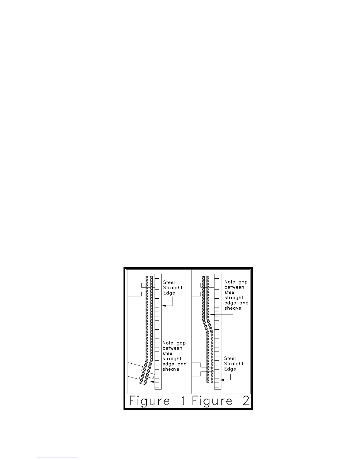
5. The two most common causes of misalignment are shown in the drawing.
a). The engine drive shaft pulley and the blade shaft are not parallel.[See figure 1]
b). The pulleys are not located properly on the shafts.[See figure 2]
6). To check alignment, all you need is a steel straight edge.
7). Line up the straight edge along the outside face of both pulleys as shown in the
drawing.
8). Misalignment will show up as a gap between the pulley face and the straight edge.
9). Make sure that the width of the outside land is equal on both pulleys.
21
Page 22

III. MAINTENANCE
B. Motor
The motors are specially designed for masonry sawing. It is totally enclosed and the
sealed bearings require no lubrication. The motor is equipped with thermal overload
protection.
1. Periodically clean the dirt and sludge build-up from the motor fan housing and
cooling fins.
2. If the motor becomes overheated, the protector shuts the motor off. Turn the motor
switch to the "OFF" and identify the cause of overheating.
For any Electric Motor service, warranty, or technical related questions please contact your
nearest Baldor service center:
Baldor Electric Company
Corporate Headquarters
5711 R.S. Boreham, Jr. St.
P.O. Box 2400
Fort Smith, AR 72901
Phone: (501) 646-4711
Fax: (501) 648-5792
Web Page: http://www.baldor.com/support/default.asp
C. Engine
1. Refer to the engine owner’s manual for complete maintenance.
a. Pre-cleaner: every 25 operating hours, more often in dusty or dirty
conditions, wash and oil the pre-cleaner.
b. Paper Element: Every 100 operating hours, more often under dusty or dirty
conditions clean the paper element.
c. Engine Oil: After the first month or 20 operating hours, change the oil, then
every 6 months or 100 operating hours.
For any Engine service, warranty, or technical related questions please contact your nearest
Honda service centers:
Honda Power Equipment Group
4900 Marconi Dr.
Alpharetta, GA 30005-8847
Tel: (800) 426-7701 | Fax: (678) 339-2670
Web page: http://www.honda-engines.com/dis.htm
D. Blade Shaft Bearings
The blade shaft bearings are lubricated and should not require daily lubrication
under normal conditions. However, to assure long life the bearings do need to be
lubricated periodically. The time interval between greasing is dependent on the running
speed and operating conditions. The following chart covers most situations and can be
used as a guide.
TEMPERATURE CLEANLINESS
GREASING INTERVAL
*UP TO 150 F Dirty 6 to 12 months
Over 150 F Dirty Daily to 2 Weeks
Any Temp Very Dirty Daily to 2 Weeks
Any Temp Extreme Conditions Daily to 2 Weeks
22
Page 23
Note: Never operate saw without bearing cover in place.
For normal conditions the grease should conform to the NLGI grade two consistency
and be free of any chemical impurities such as free acid or free alkali, dust, rust, metal
particles or abrasives.
For best results, the bearings should be lubricated while in operation.
Note:
Due caution for personal safety must be observed when servicing rotating
equipment.
If necessary to lubricate while the bearing is idle, refer to lubrication table for the
maximum grease capacity for the bearings.
E. Pump
The submersible pump is mechanically driven by the V-belts and the sealed bearings
require no lubrication. The pump is designed to run wet or dry, but for continued dry
cutting, disconnect the pump.
1. Be sure to keep the pump clean - do not allow sediment to cake in the pump and
2. Keep all lines clean and running free.
3. Do not allow the Flex-cable to be pinched by the blade guard or anything else.
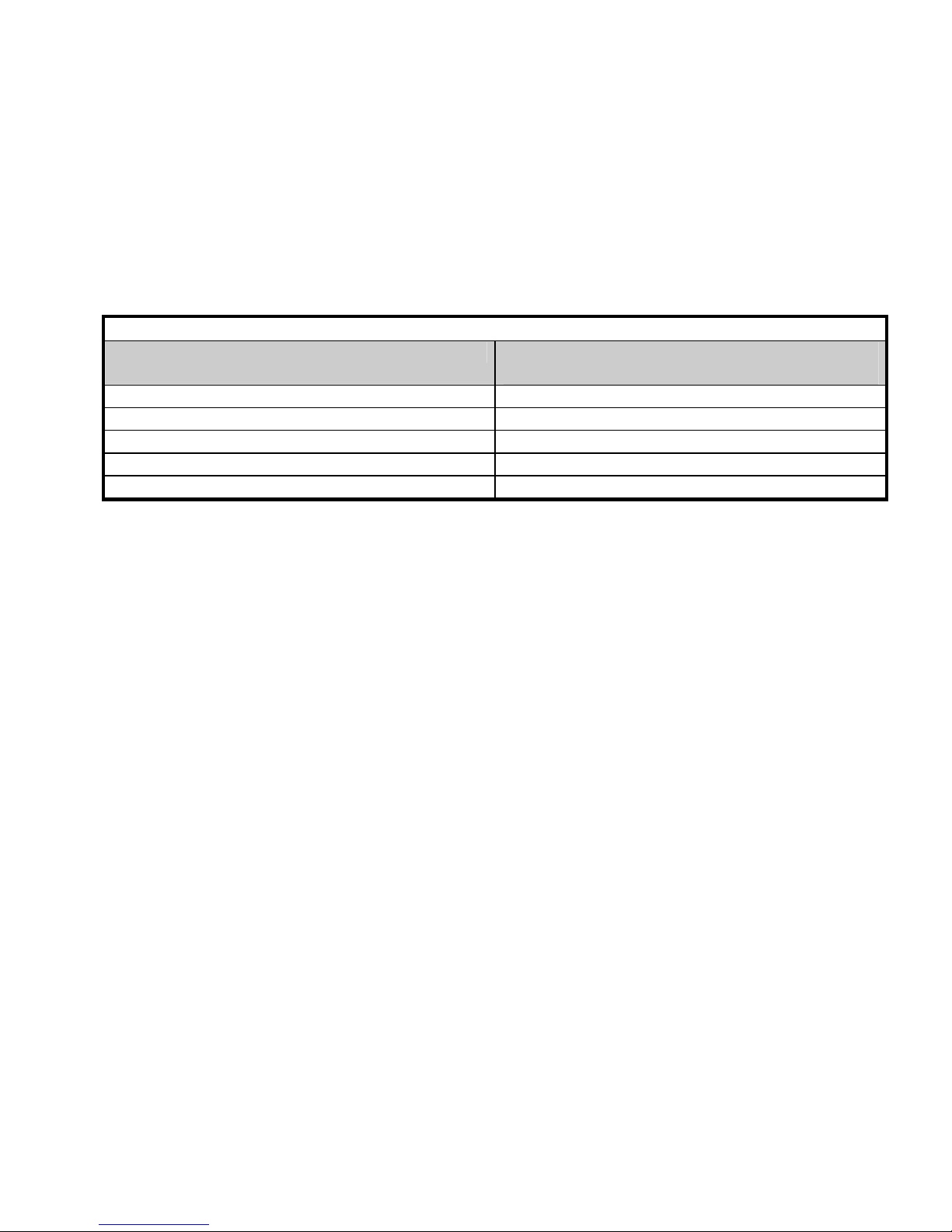
LUBRICATION OF SEALMASTER BEARINGS
Shaft Sizes Maximum Grease Capacity of Bearing
Chamber in Ounces
1/2" to 3/4" .09
7/8" to 1-3/16" 1/4
1-1/4" to 1-1/2" 3/8
1-11/16" to 1-15/16" 3/4
2” to 2-3/16" 1-1/8
clog it.
Damage to the flex cable by pinching is not covered under any warranty
23
Page 24

V. PARTS LIST SECTION
A. Ordering Information
1. List model number and serial number of machine.
2. List the part number and description of part (not item number).
3. Whenever alternate parts are shown due to product improvement, inspect the part you
have and provide additional description as necessary.
4. Specify mode of shipping desired, for example, parcel post, truck, airfreight, U.P.S., best
way, etc.
B. Parts List
See assembly drawing.
C. Power Unit Service Information
Repair or replacement service is available from your nearest authorized service station. Refer
to the service center listing for the nearest authorized motor/engine service center.
24
Page 25
V. PARTS LIST SECTION
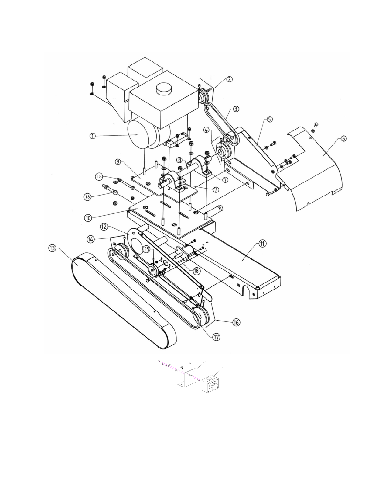
Power Plant (BBC547) Gasoline
S1
S2
25
Page 26

Power Plant (BBC547) Gasoline
Item No Description Part Number
1 Honda motor GX160 83715
2 Motor pulley 83716
3 Belt XPZ 562 LW 83717
4 Jackshaft pulley 83718
5 Right belt guard 83719
6 Guard for the jackshaft 83720
7 Bearing 70599
8 Jackshaft 83721
9 Motor fixation plate 83722
10 Jackshaft fixation plate 83723
11 Cutting head 83724
12 Support plate for belt guard 83725
13 Belt guard 83726
14 Jackshaft pulley 76102
15 Water pump pulley 75270
16 Blade shaft pulley 76098
17 Belt XPZ 1280 LW 70398
18 Eyebolt with Hardware (1) 76015
S1 Switch support 83746
S2 Emergency stop switch 83745
26
Page 27
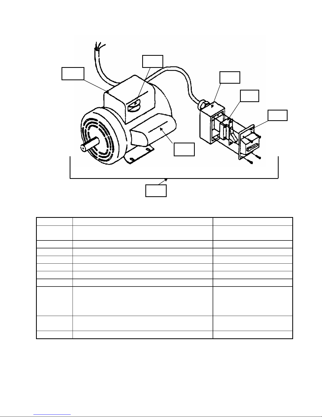
Power Plant (BBC157-207) Electric
M3
M2
M4
M5
M7
M1
Item No Description Part Number
M1 Motor Assembly w/Switch 1-1/2HP 115/230v/60/1
Motor Assembly w/Switch 2 HP 115/230v/60/1
232084
232085
M2 Capacitor Box Large (Terminal Box) 232085A
M3 Voltage Change Switch 231085
M4 Switch Box Rear 231087
M5 Switch On/Off 231089
M6 Switch Box Cover 231088
M7 Capacitor Box Small 231091
-NA- Thermal Reset Button 1-1/2 HP
Thermal Reset Button 2 HP
NOTE: The Thermal Reset Button Is Located On
The Rear Of The Large Capacitor Housing
-NA- Pulley 68MM OD 24MMB 1G Electric Models
83747
Only
-NA- Belt XPZ 1500 LW (1) Electric Models Only 72926
M6
27
Page 28
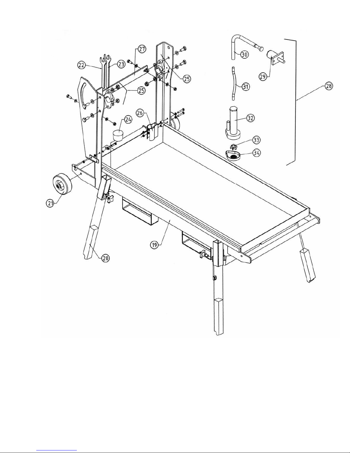
Frame (Common All BBC157-207-547))
28
Page 29

Frame (Common All BBC157-207-547))
Item No Description Part Number
18 Screws for water pump 75280
19 Frame 83727
20 Leg set of 4 75817
21 Wheel 82733
22 Wrench 19mm 70807
23 Wrench 22mm 72143
24 Drain plug 76095
25 Splited bearing 83728
26 Water pump fixation spring 76097
27 Support post 83729
28 Water pump complete. 72305
29 Drive end comp. For water pump 72297
30 Sheath for flexible shaft
(Not Available, Now part of 72307)
31 Flexible shaft complete for mech. water pump
L=35.8 inches (910mm)
32 Body of the pump 72284
33 Propeller water pump 72862
34 Plastic sieve for pump 72186
-NA- Knob M10 X 20 1.5 for Legs (sold each) 72856
-NA- Part of 72307
72307
29
Page 30
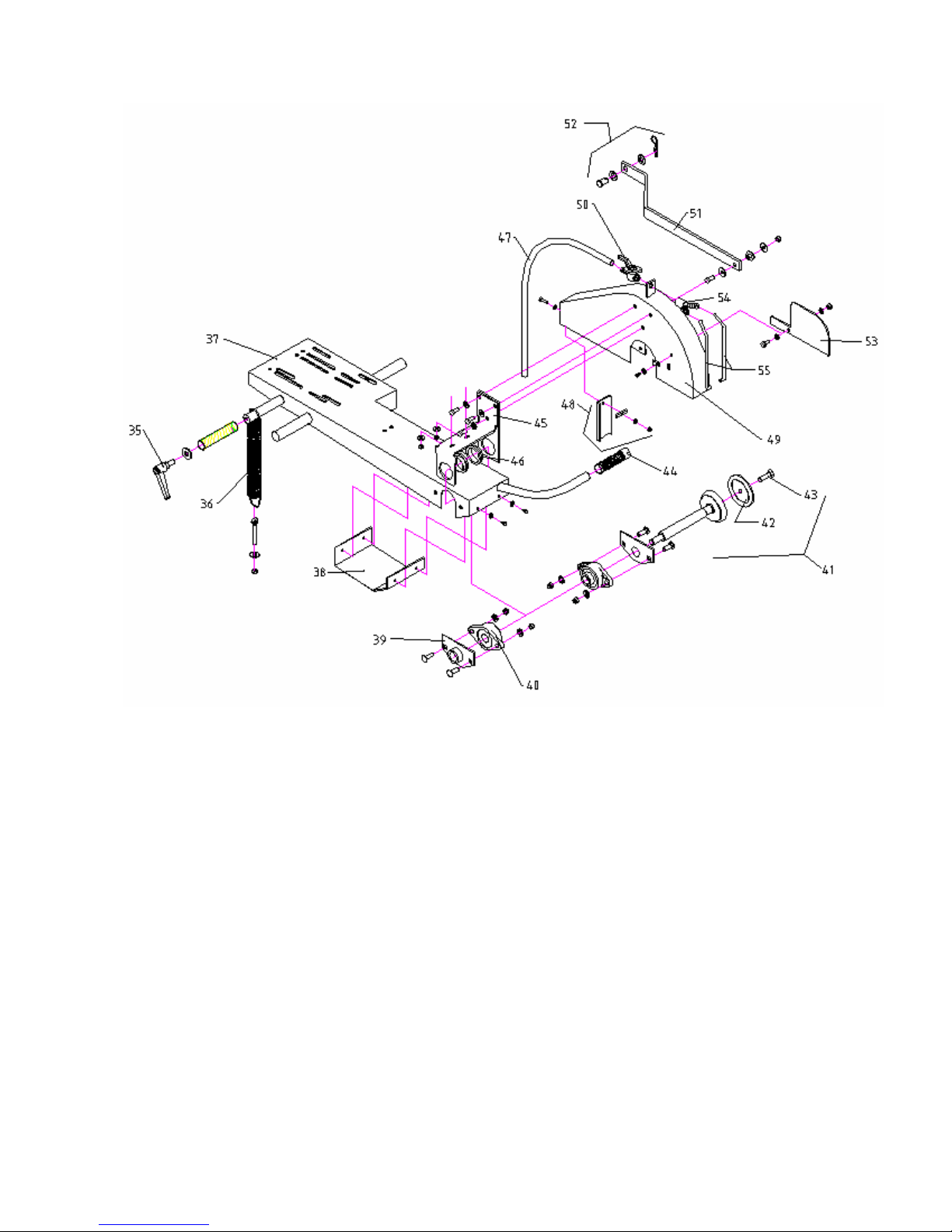
Cutting Head (Common All BBC157-207-547)
30
Page 31
Cutting Head (Common All BBC157-207-547)
Item No Description Part Number
35 Locking Handle for cutting head (was 73098
replaced by 82738)
36 Spring 72567
37 Cutting head 83724
38 Protection for Bearings and shaft 76111
39 Support for blade shaft bearing (set of 2) 76060
40 Bearing (set of 2) 73418
41 Blade shaft assembly 76035
42 Loose collar 73216
43 Screw for loose collar 73217
44 Handle grip 72097
45 Leveling support 76113
46 Bushings, bearing-Nylon (set of 2) 73220
47 Hose for water pump 72413
48 Splash guard 73221
49 Blade guard 76037
50 Water tap 72357
51 Stay-level arm 73266
52 Kit stay-level arm pin 76039
53 Blade shaft vent cover 76109
54 Y distributor 72286
55 Spray nozzle (set of 2) 80568
82738
31
Page 32
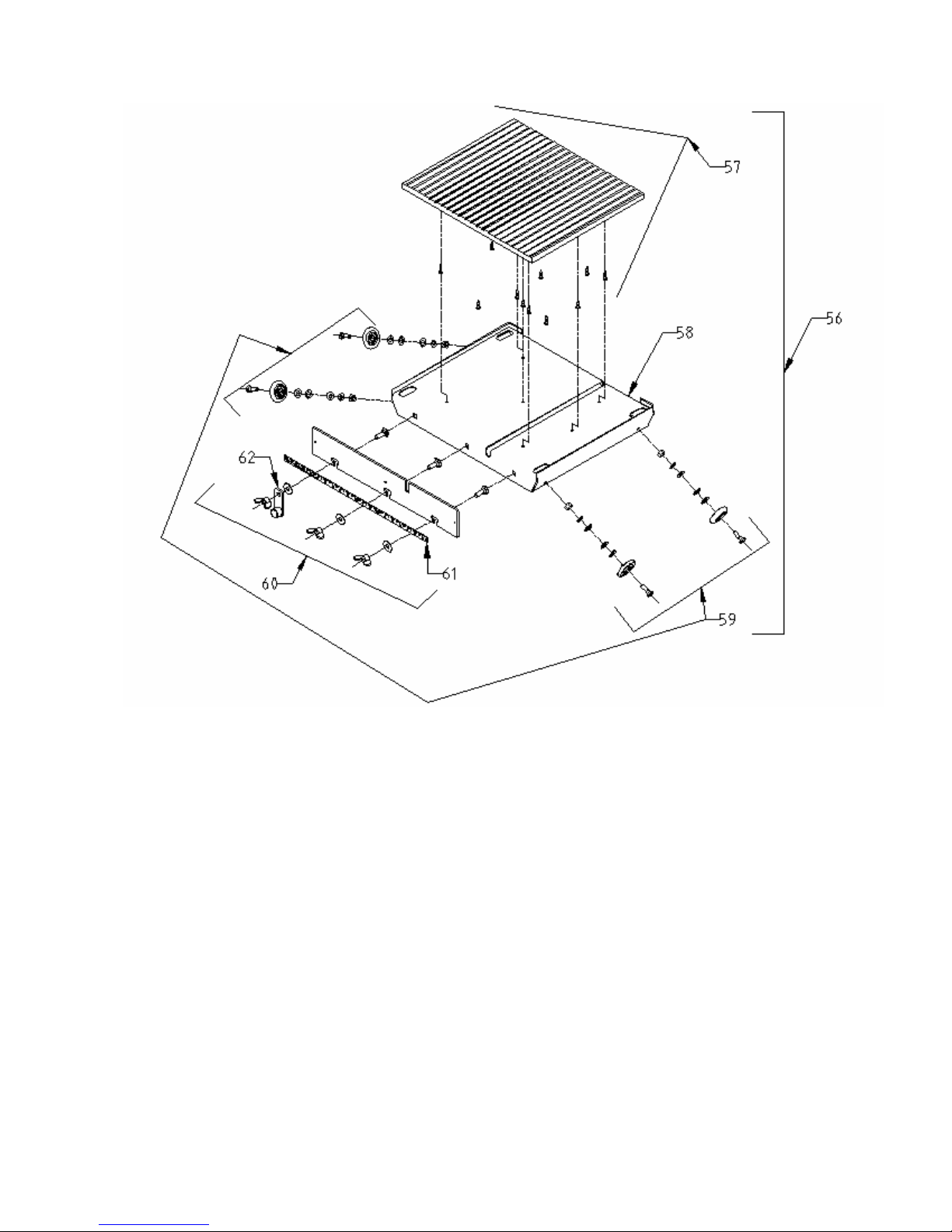
Cutting Table (Common All BBC157-207-547)
32
Page 33
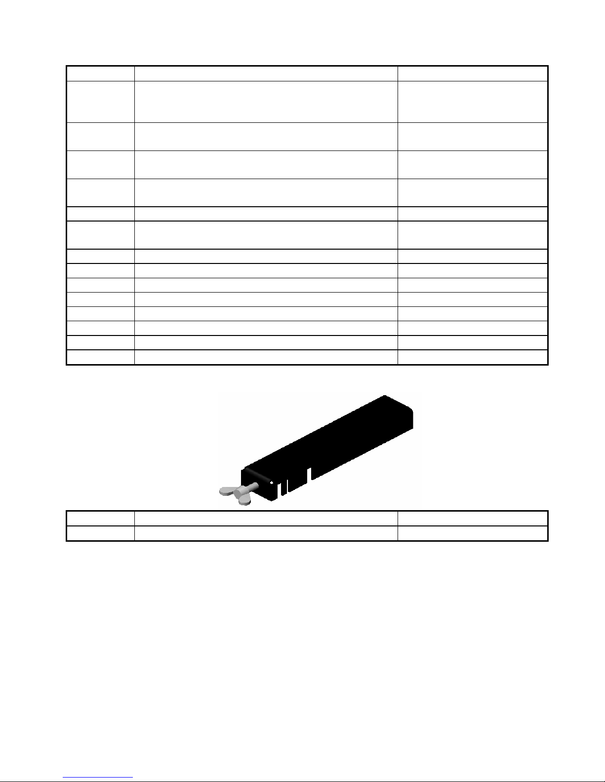
Cutting Table (Common All BBC157-207-547)
Item No Description Part Number
56 Conveyor Cart (aka Cutting Table) Complete
With Wheels, Top, Back Stop, and Conveyor Cart
Stop
57 Top For Cutting Table (Wood & Rubber)
w/Hardware
Screw 4x 12mm DIN 7976 (sold each, 11
required)
58 Conveyor Cart Frame Only (No Wheels, Top,
-NA- Part of 83754
Backstop or Conveyor Cart Stop)
59 Wheel Kit, Conveyor Cart (Set Of 4) w/Hardware 75333
Carriage Bolt M10 x 30 DIN 603 (sold each, 3
required)
Washer 10.5 DIN 9021 (sold each, 3 required) 27508
Wing Nut M10 DIN 315 (sold each, 3 required) 27040
60 Back Stop Plate 83752
61 Scale for Conveyor Cart w/rivets 83753
62 Stop Assembly for Conveyor Cart (Complete) 82856
Rubber Stop -NA- Part of 82856
Nut M6 DIN 439 27003
Washer M6 DIN 125 27539
83754
76742
30373
27282
Item No Description Part Number
-NA- Guide-A-Cut Assembly 83892
33
Page 34
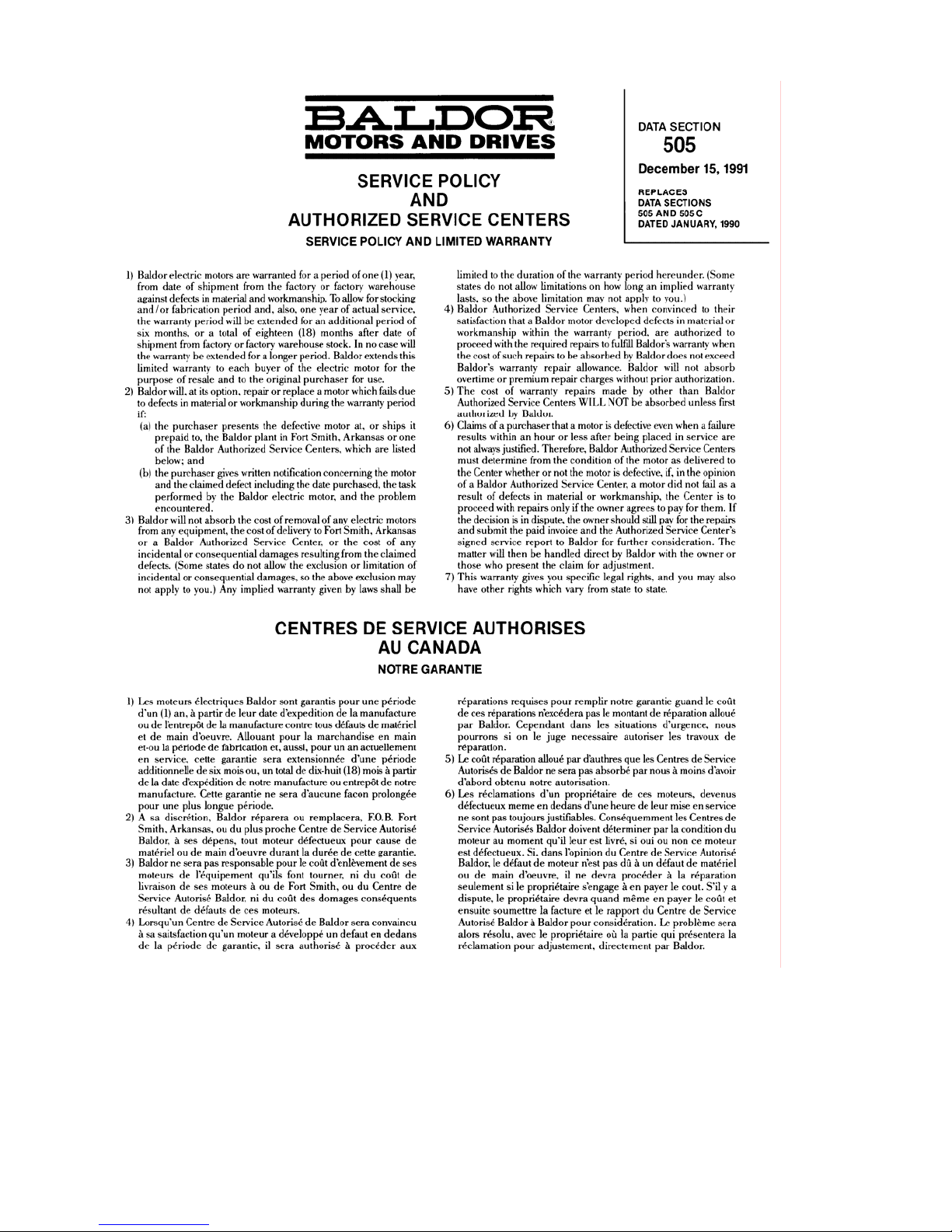
C. Baldor Service Policy
34
Page 35
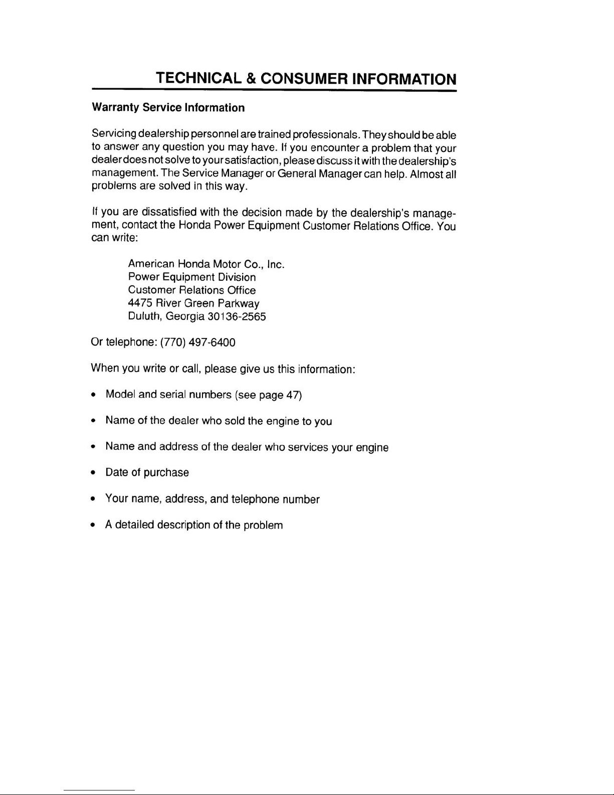
D. Honda Service Policy
35
Page 36

Saint-Gobain Abrasives, Inc.
Norton Construction Products
2770 West Washington Street
Stephenville, TX 76401
Phone: 800-554-8009 or 254-918-2310
Fax: 800-443-1092 or 254-918-2312
Some dust created by power sanding, sawing, grinding, drilling,
and other construction activities contains chemicals known to
cause cancer, birth defects or other reproductive harm. Some
examples of these chemicals are:
• Lead from lead-based paints,
• Crystalline silica from bricks and cement and other masonry
products, and
• Arsenic and chromium from chemically-treated lumber.
Your risk from these exposures varies, depending on how often
you do this type of work. To reduce your exposure to these
chemicals: work in a well ventilated area, and work with approved
safety equipment, such as those dust masks that are specially
designed to filter out microscopic particles.
SOLD AND SERVICED BY:
36
 Loading...