

Clippasafe 122 Pressure Fit Gate User Manual
Pressure Fit
Gate (Wood)
WIDTH
Adjustable from 72 to 80 cm
HEIGHT
Top of gate to floor 78 cm
A
x 3
L
x 1
B
x 3
C
x 2
D
x 4
E
x 1
WARNING - INCORRECT FITTING
OR POSITIONING OF THIS SAFETY
BARRIER CAN BE DANGEROUS
Fixing surfaces must be suitable
for the purpose and structurally
sound.
This product requires the purchase
of appropriate fixing aids suitable
for the surface to which the wall
cups are to be fitted.
If this gate needs to be fitted to
a round shaped newel post,
‘Y’ shaped spindles are available
separately which replace the screw
adjusters and wall cups supplied
with this gate.
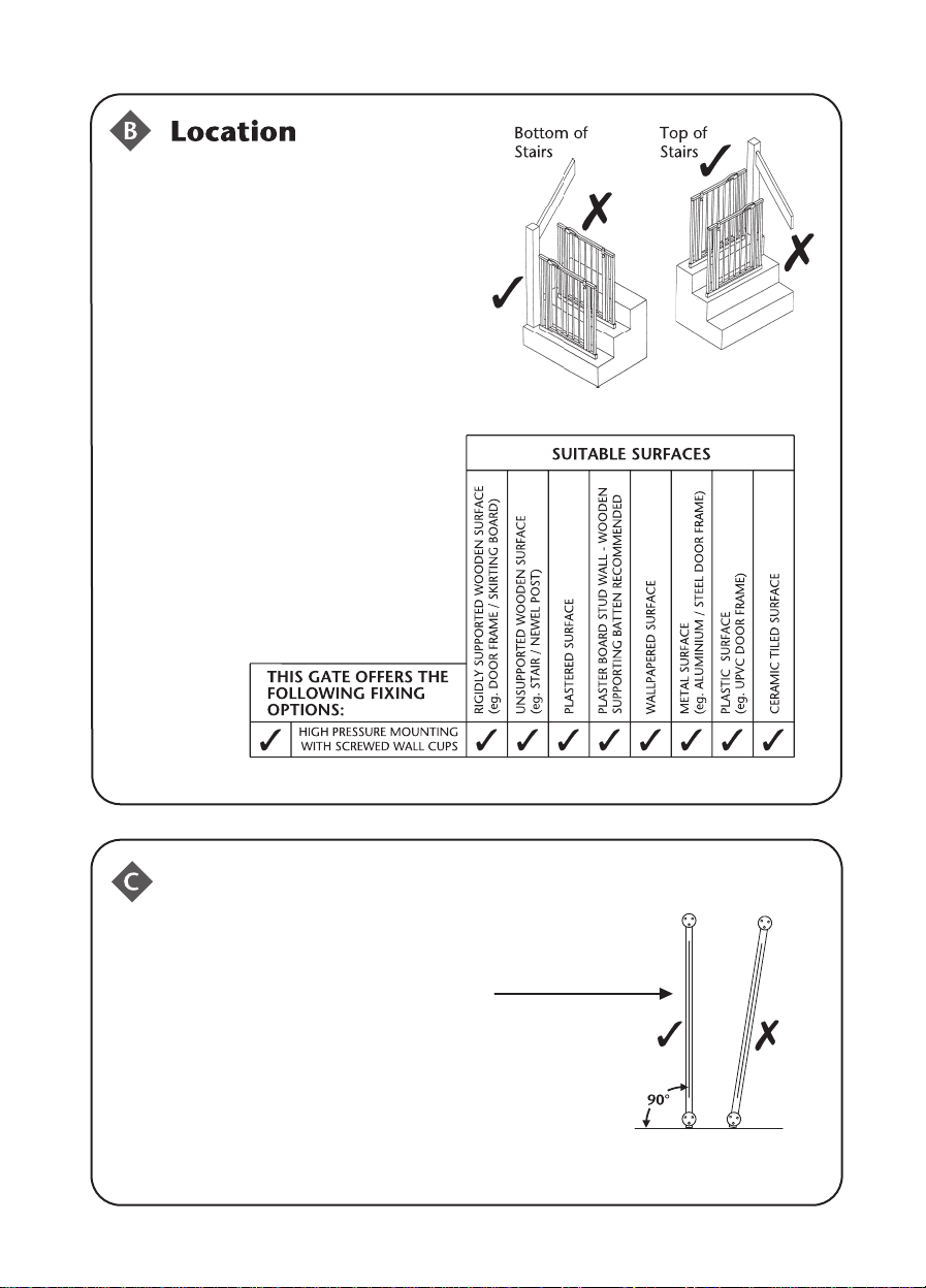
Pre-Installation Advice
WARNING - NEVER USE WITHOUT WALL CUPS
WARNING - GATE MUST BE FITTED UPRIGHT
AS SHOWN
WARNING - THE GATE SHOULD BE POSITIONED
SO THAT IT OPENS AWAY FROM THE STAIRS
Installation
1
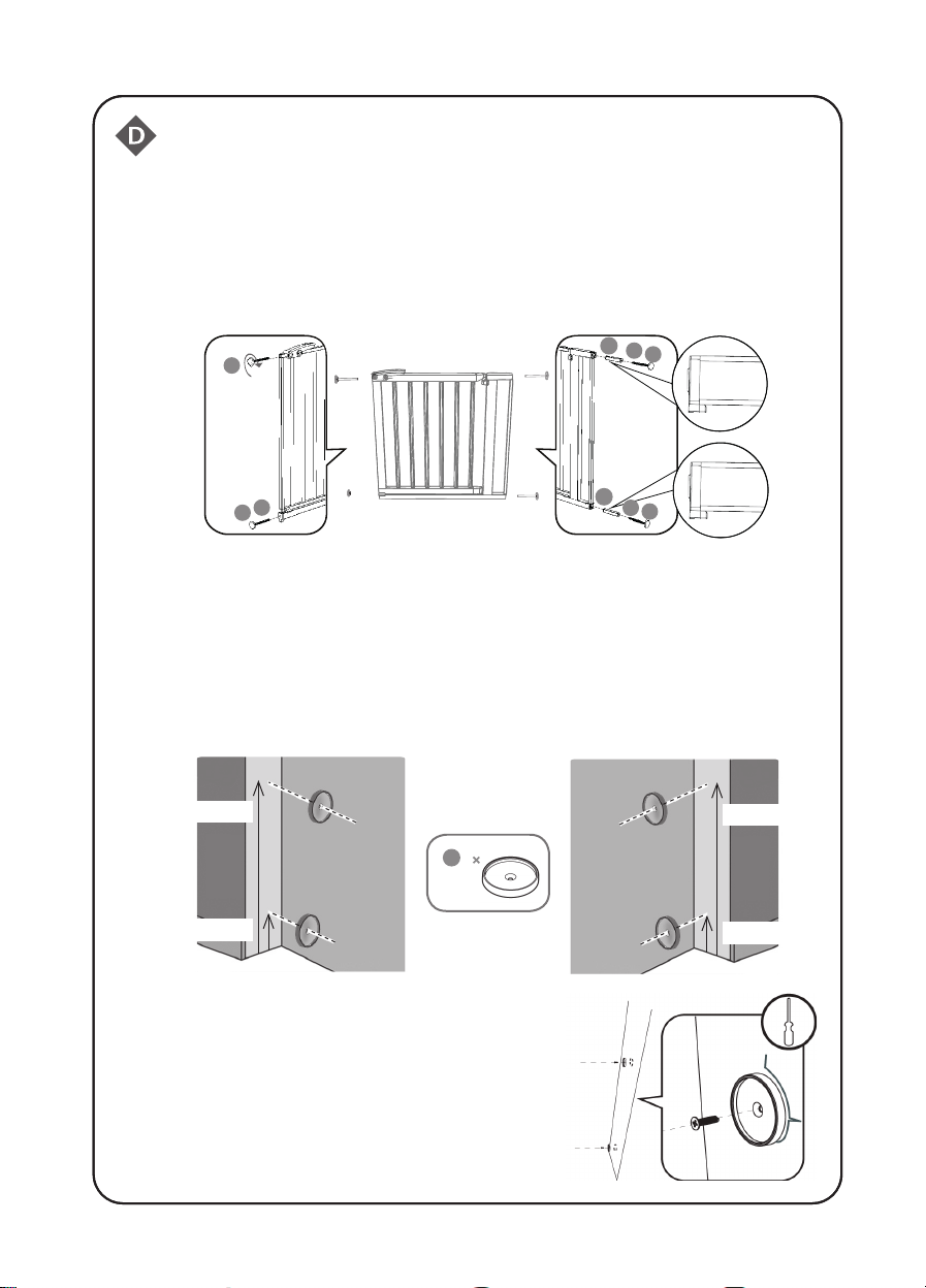
On the latch side of the gate, insert 1 screw adjuster ‘A’ with nut ‘B’ into the
holes provided on the bottom of the gate. Screw the screw adjuster ‘L’ into
the hole provided next to the handle. On the other side of the gate insert 2
casings ‘C’ followed by 2 screw adjusters ‘A’ with nuts ‘B’ into the holes
provided. Be sure to insert both casings ‘C’ with the notch facing
downwards.
C
B
L
A
B
A
Mark the position for the wall fixings ‘D’ on the wall surface you wish the
2
C
B
A
gate to hinge from. The hole for the lower wall fixing should be 26.5mm
from the floor. The hole for the upper wall fixing should be 721.5mm from
the floor. On the other side of the opening mark the position for the wall
fixings ‘D’. This should be the side you want the gate to open from. The
hole for the lower wall fixing should be 26.5mm from the floor. The hole
for the upper wall fixing should be 716.5mm from the floor.
721.5mm
26.5mm
D
4
716.5mm
26.5mm
Fix the wall fixings ‘D’ using the appropriate
fixings depending on the surface available:
wood screws for wooden surfaces, multi-use
dowel and concrete screws for concrete
surfaces, multi-use dowel and cement screws
for cement surfaces, metal screws for metal
surfaces. These screws are not provided.
 Loading...