

Page 1

1
Page 2

2
1. CG-410 FEATURES.........................................................................................................................3
2. PARTS CHECKLIST ........................................................................................................................4
3. CONTROLS AND FUNCTIONALITIES ........................................................................................5
4. INSTALLING THE CG-410 .............................................................................................................8
5. CONFIGURING THE COMPUTER NETWORK ..........................................................................9
6. CONFIGURING THE CG-410.......................................................................................................13
7. USING THE CG-410 ......................................................................................................................29
8. UPGRADING THE FIRMWARE...................................................................................................32
Contents
Page 3

3
1. CG-410 Features
4-channel FXO Gateway with 2xport Ethernet switch
Robust CPTD function for various tone configurations
NAT (Network Address Translation) & Port Mapping available to use IP phone and neighbored
computers concurrently in a single IP environment
Acts as a switching hub in a multi-IP environment
Supports private Internet lines, xDSL and cable modem
Supports secure FXO Access and call forwarding
Easy management at the remote site through a built-in web server
Includes NAT traversal functionality
Chapter1
Page 4
4
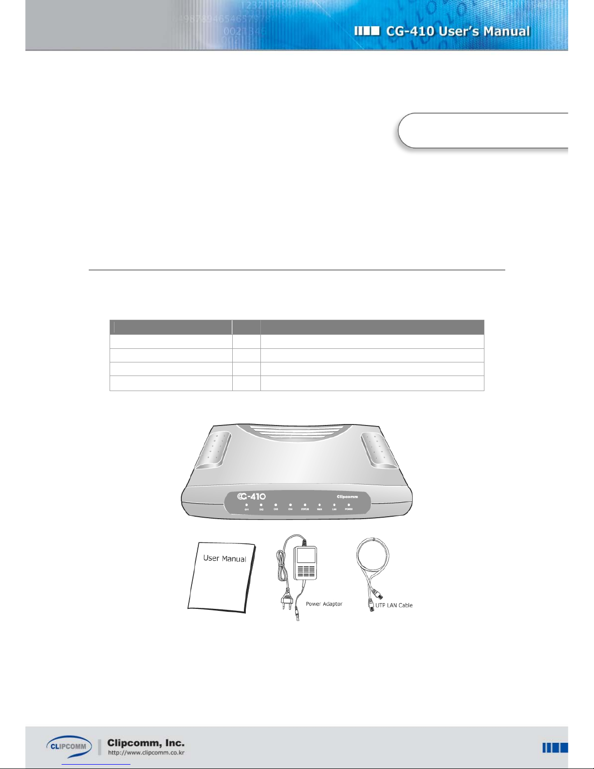
2. Parts Checklist
Check the components below before you proceed with the next stages to install your CG-410.
Item Q’ty Description
CG-410 1 CG-410 main body
User manual 1 Description of product features and functionalities
Power adapter 1 Power supply
LAN(UTP) cable 1 RJ45 LAN cable to access the network
Chapter 2
Page 5

5
3. Controls and Functionalities
Chapter 3
Page 6

6
3.1. Front Panel LED
(From left to right)
LED
Name
Color Status Description
On PSTN connected to the “CH1” port is in use.
CH1 Green
Off PSTN is not in use.
On PSTN connected to the “CH2” port is in use.
CH2 Green
Off PSTN is not in use.
On PSTN connected to the “CH3” port is in use.
CH3 Green
Off PSTN is not in use.
On PSTN connected to the “CH4” port is in use.
CH4 Green
Off PSTN is not in use.
On
Ready for VoIP calls through the Internet telephony
server.
Blinking Upgrading the Firmware is in progress.
Rapidly
Blinking
Failure in registering on the Internet telephony server.
STATUS Green
Off Other cases.
On Link is detected at the WAN port.
Blinking Receiving or transmitting data through the WAN port.
WAN Green
Off No link is detected at the WAN port.
On Link is detected at the LAN port.
Blinking Receiving or transmitting data through the LAN port.
LAN Green
Off No link is detected at the LAN port.
On Successful power supply to the CG-410.
POWER Red
Off No power supply to the CG-410.
Page 7

7
3.2. CG-410 Rear Panel
Refer to the description below of each port at the rear panel of your CG-410.
(From left to right)
Port Name Description
POWER Connect the power adaptor here for power supply.
COM Connect the DIN-6PIN serial port here.
RESET
Press this button for more than three seconds to restore the original factory
default setting of your CG-410.
LAN Connect the LAN cable to the co-located computer.
WAN
Connect the LAN cable here and link it to the dedicated line, ADSL / VDSL
modem or cable modem.
CH4 Connect the PSTN line here.
CH3 Connect the PSTN line here.
CH2 Connect the PSTN line here.
CH1 Connect the PSTN line here.
Page 8

8
4. Installing the CG-410
Once you have checked all of the items, follow the next steps to install your CG-410.
① Pull out the PSTN lines from your telephones and connect them to “CH1,” “CH2,” “CH3” and
“CH4” port.
② Connect the LAN cable (RJ-45) linked with the Internet to the “WAN” port.
③ Connect one end of the supplied LAN cable (RJ-45) to the LAN card of your computer, and
the other end to the “LAN” port at the rear panel of the CG-410 to use the NAT or the
switching HUB function of your CG-410.
④ Connect the power adapter to the “POWER” port of the CG-410.
※ Caution: Use only the power adaptor that Clipcomm provides. Using other power adapters
may cause the CG-410 to malfunction.
Chapter 4
Page 9
9
5. Configuring the Computer Network
Once you have installed your CG-410, you should reconfigure the network settings by using the CG-
410 and the computer which is connected to the LAN port. This process will allow you to configure
your CG-410’s network and the VoIP settings. Choose the version of your operating system from
below, and follow the steps that match it.
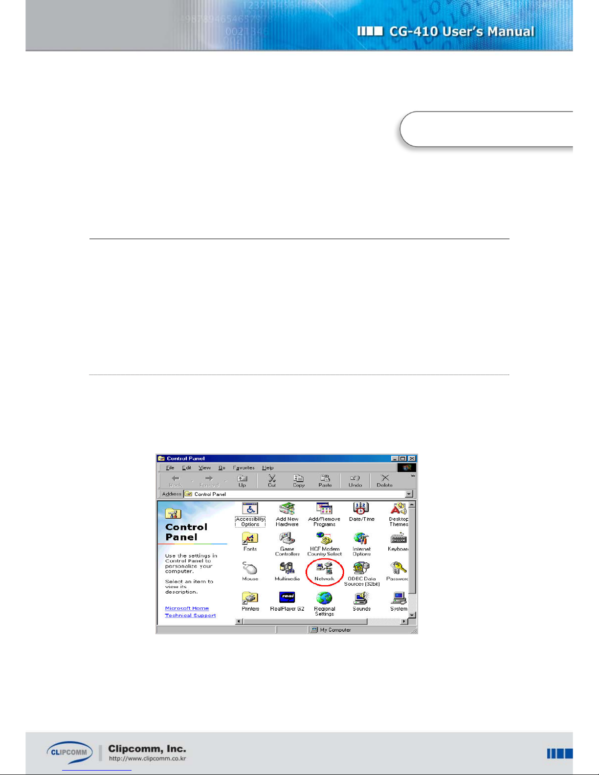
5.1. For Windows 98 / Windows ME
① Click [Start] from the bottom menu bar, and then choose [Settings].
② Select [Control Panel] to view a new window, and then choose [Network].
③ Now select [TCP/IP] and press [Properties]. If there are more than one TCP/IP
adapters, choose the one that is currently in use.
Chapter 5
Page 10

10
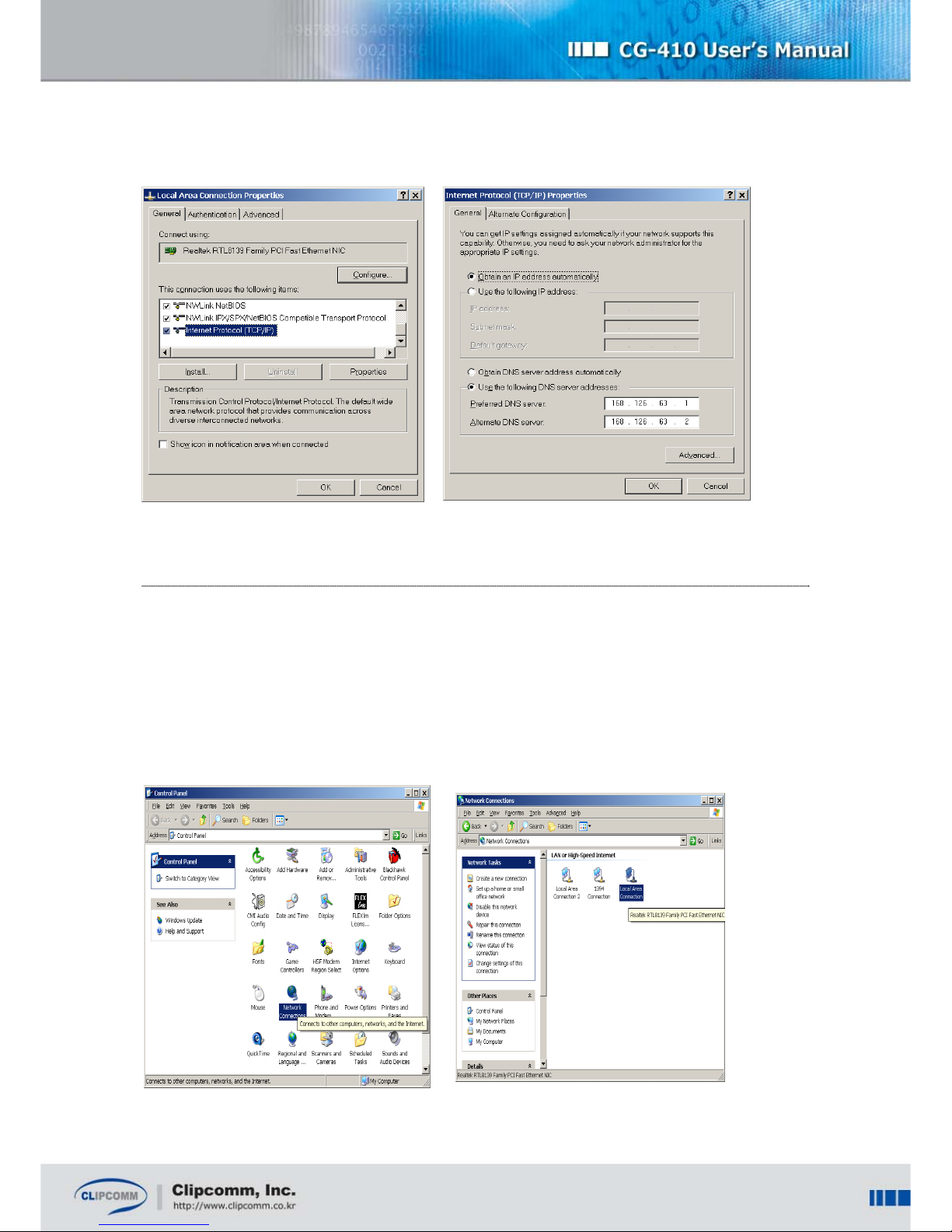
④ Click [IP Address], and then check the [Obtain an IP address automatically] box. If the box is
already checked, you don’t need to change anything.
⑤ Click [OK] and restart your computer.
5.2. For Windows 2000
① Click [Start] from the bottom menu bar, then choose [Settings].
② Select [Control Panel] to view a new window, and then choose [Network and dial up
connections].
③ Right click on [Local Area Connection]. If there are more than one Local Area Connections,
choose the one that is currently in use.
④ Choose [Properties] when a new window appears.
⑤ Now select [TCP/IP] and then press [Properties].
⑥ Click [IP Address] tab and then check the [Obtain an IP address automatically] box. If the box
is already checked, you don’t need to change anything.
⑦ Click [Ok]. You don’t need to restart your computer in Windows 2000.
Page 11
11
5.3. For Windows XP
① Click [Start] from the bottom menu bar, then choose [Settings].
② Select [Control Panel] to view a new window, and then choose [Network connections].
③ Right click on [Local Area Connection]. If there are more than one Local Area Connections,
choose the one that is currently in use.
Page 12

12
④ Choose [Properties] when a new window appears.
⑤ Now select [TCP/IP] and then press [Properties].
⑥ Click [IP Address] tab and then check the [Obtain an IP address automatically] box.
If the box is already checked, you don’t need to change anything.
⑦ Click [Ok]. You don’t need to restart your computer in Windows XP.
Once you have successfully configured the network settings of your computer, you can access the
built-in web server with your computer in order to configure CG-410’s network settings. For more
details, see Chapter 6.
Page 13

13
6. Configuring the CG-410
Before you run your CG-410, make sure the computer’s settings have been configured properly. Now
you can configure the CG-410’s settings by using its built-in web configuration pages.
6.1. Configuring the Network
6.1.1. Configuring the Network with Web Interface
① Connect your computer to the LAN port of the CG-410. For details, refer to the procedures in
Chapter 4 and 5.
② Open a web browser in your computer and type http://192.168.120.1:1001
in the browser’s
address bar.
③ Type [admin] as the user ID and [0000] as the password.
You will be able to access the built-in web configuration pages of the CG-410.
Chapter 6
Page 14

14
④ Select [System Configuration], and then choose [Network] to enter the network configuration
page.
⑤ Now select the appropriate IP configuration parameter that matches your network
environment from below, and then follow the steps that fit your case.
(a) Static IP;
i. Select [Static IP].
ii. Enter the IP, gateway, network mask and DNS address for CG-410.
(b) DHCP(Dynamic IP) or Cable modem;
i. Select [DHCP].
(c) ADSL(PPPoE);
i. Select [ADSL].
ii. Enter ADSL ID and the password.
Page 15

15
⑥ If you have completed all of the entries, click [save and restart].
⑦ CG-410 will automatically restart with the new parameters.
6.1.2. Configuring the Network by using Serial Interface (COM)
You have the option to view and change your CG-410’s network configuration by using its serial
interface (COM) and the proprietary serial cable.
By default, the proprietary serial cable is not included in the CG-410 package. Please
contact Clipcomm technical support personnel about procuring the serial cable.
① Connect your computer’s COM port and CG-410’s serial interface by using the proprietary
serial cable.
② Run a console emulation program such as “Hyper Terminal” on the computer.
Page 16

16
③ Set the connection parameters of the console emulation program by the following steps
below:
(For more details on the connection parameters, refer to the user guide of the console
emulation program.)
Port: COM port number of the computer where the serial cable is connected.
Baud rate: 115200 bps
Data Bits: 8
Parity: None
Stop Bits: 1
Flow Control: None
The example below displays the console through the serial interface after booting the CG-410 is
completed successfully.
System Ready...
CLIP@192.168.0.216>
④ Enter “ipcfg <enter>”, then the message below will appear. You can select one of the IP
address configuration methods among; 0 (Static IP) / 1(DHCP) / 2(ADSL) that matches your
network environment.
CLIP@192.168.0.216> ipcfg <enter>
IP Configuration Help
Help display this message
Exit exit from this menu
Select IP configuration method
0) Static IP
1) DHCP
2) ADSL
ipcfg >
⑤ When you complete the network settings, a message asking if all of the parameters have
been set correctly will appear. Type “Y <enter>” to save the parameters.
The example below shows the confirmation message when the IP setting mode is set as “Static
Page 17

17
IP.”
Static IP configuration complete
Network configuration is changed
Method : Static IP
IP Address : 192.168.0.166
Gateway Address : 192.168.0.4
Netmask : 255.255.255.0
DNS Address : 168.126.63.1
Do you want to save (Y/N)?
⑥ Press “Y<enter>” to apply new parameters that you have saved, then CG-410 will restart
automatically with the changed parameters.
New configuration is saved
The system will restart to apply the new configuration
Do you want to restart now (Y/N)?
6.1.3. Configuring the Network System
① Select [System Configuration] on the left side, and then choose [Network] to enter the
network configuration page.
② Set each configuration parameters with appropriate value.
Item Description Default
External Enet
Address
Indicates the external Enet address of your CG-410. It is
recommended that you do not change the default value.
External
Enet
Address
NAT
Enable: CG-410 exercises as NAT router. Thus CG-410’s
LAN port connected to the PC or network devices is able to
contact external network with its private IP address.
Disable: CG-410 exercises as HUB. Thus CG-410’s LAN
port connected to the PC or network devices has the same
enable
Page 18

18
IP address on the same subnet as CG-410.
Private
Network
Address
When CG-410 uses NAT and DHCP server, it assigns the
private IP address field to CG-410’s LAN port connected to
the PC or network devices with the value that you set.
Ex) 192.168.120.1
120
DHCP server
CG-410 exercises as DHCP server.
enable
DHCP Pool
When CG-410 exercises as DHCP server, it assigns the
private IP addresses to CG-410’s LAN port connected to the
PC or network devices within this pool.
Ex) 192.168.120.4 ~ 192.168.120.135
4~135
6.2. Configuring the Port Mapping
Applying the Port Mapping function allows you to operate some server programs on your computer
that is connected to the CG-410’s LAN port.
The following example illustrates how you can operate the FTP server on the PC (192.168.120.9).
Direction (Incoming)
Protocol (TCP)
Client IP Address (192.168.120.9)
Client Port (21)
NAT Port (21)
Push Insert button.
This procedure lets all the TCP data coming into the 21 port of CG-410 to be delivered to the 21 port
on the PC (192.168.120.9).
The following example illustrates how you can operate the FTP server on another PC
(192.168.120.22).
Direction (Incoming)
Protocol (TCP)
Client IP Address (192.168.120.22)
Page 19

19
Client Port (80)
NAT Port (80)
Press Insert button to restart.
Similarly, all the TCP data coming into the 80 port of CG-410 will be delivered to the 80 port of the PC
(192.168.120.22).
6.3. Configuring the VoIP
Before using the VoIP functions of your CG-410, make sure the settings related to a specific VoIP
protocol are configured correctly. CG-410 supports both H.323 and SIP protocols. Please contact ITSP
or the network administrator for more information on VoIP configurations.
6.3.1. Configuring the CG-410 for H.323
① Select [System Configuration] on the left side, and then choose [VoIP] to enter the VoIP
configuration page.
② Set each configuration parameters with appropriate value.
Refer to the following table about the details of each field.
Item
Description Default
Use
Gatekeeper
Determines whether the CG-410 will register at the designated
gatekeeper or not. Once enabled, CG-410 tries to communicate
with the gatekeeper whose address is specified in the
“Gatekeeper address” tab.
If the gatekeeper fails to register, STATUS LED blinks rapidly
which means that VoIP phone call is not available. In this case,
you can hear the busy tone when you pick up the phone.
disable
Gatekeeper
Address
Enter the gatekeeper’s IP address when “Use Gatekeeper” is
enabled.
0.0.0.0
Page 20

20
Gatekeeper
Password
Enter the password of the gatekeeper if you need the H.235
authentication to register.
N/A
Skip GRQ
Use this item to send RRQ ahead and skip GRQ to register with
the gatekeeper.
disable
Enable H.323
ID
Once enabled, CG-410 uses the H.323 ID as one of its aliases
to register with the gatekeeper.
disable
H.323 ID
Set the H.323 ID in this tab. Clip
Enable E.164
ID
Once enabled, CG-410 uses the E.164 ID as one of its aliases
to register with the gatekeeper.
disable
E.164 ID
Set the E.164 ID in this tab. 100
Refer to the following table for the remaining items not mentioned above. If you are not familiar with
the items below, it is suggested that you do not change the settings.
Item Description Default
Fast Start
Once enabled, CG-410 uses fast start procedure for
outgoing calls.
enable
H245 Tunneling
Once enabled, CG-410 uses H.245 tunneling procedure.
enable
Use VAD
Once enabled, CG-410 continuously monitors voice activity
and does not send voice data when it detects silence.
disable
Comfort Noise
Generation
Once enabled, and the sender uses VAD, a comfortable
noise is generated when the sender remains silent.
enable
Debug Print Level
Determines the debugging information level which is printed
through the COM port.
1
RTP Port Base
Sets the base port number of RTP which is used on H.323.
5000
Q.931 Port
Configuration
Q.931 port number can be set manually by this
configuration parameter.
Automatically
RAS Port
Configuration
RAS port number can be set manually by this configuration
parameter.
Automatically
H.245 Port
H.245 port number can be set manually by this
Automatically
Page 21

21
Configuration
configuration parameter.
Use NAT
Traversal
If you are using a private IP (behind NAT) and want to use
NAT traversal to make or receive an external call through
NAT, set "Use NAT Traversal" enable.
Otherwise, make it disable.
disable
NAT Router IP
Enter the external IP address of the NAT Router to use NAT
traversal.
N/A
To use NAT Traversal, open a unique set of H.323 signaling (Q.931, RAS, etc) and RTP port/address
pairs at NAT router. This process will enable your CG-410 to make and receive calls through NAT.
Setting up these ports is called Port mapping, which enables your CG-410 to run behind the NAT
router.
6.3.2. Configuring the CG-410 for SIP
① Select [System Configuration] on the left side, and then choose [SIP] to enter the SIP
configuration page.
② Set each configuration parameters with appropriate value.
Refer to the following table about the details of each field.
Item Description
SIP Server Configures the URI of the SIP Server.
Register On Enable it to register on the server.
Registrar Server Configures the URI of the Registrar Server.
Outbound Proxy Configures the URI of the SIP Proxy when Proxy is used.
Proxy Port Configures the port of the Proxy server.
User ID Determines the telephone number which is set as User information.
Display Name Determines the name which is set as User information.
Authentication ID Determines the ID which is set as User information.
Page 22

22
Password
CG-410 encrypts this key value as a response when authorization is
asked.
RTP Port
RTP port number can be set manually by using this tab. It is
recommended that you use the default value.
Expiry Timer Specifies the expiry of registering or reregistering attempt.
SIP Local Port Configures the port of CG-410 for SIP communication.
Voice Codec Specifies the voice codec used for VoIP calls
NAT Traversal
Select “STUN” to use NAT traversal by using STUN server.
Select “Manual” to use NAT traversal without STUN server.
STUN Server
If you select “STUN” for NAT traversal, enter the address and the port of
STUN server.
NAT Router IP
If you select “Manual” for NAT traversal, enter the external IP address of
NAT router.
NAT Timer
Determines the periodic time of sending the packet in order to maintain
NAT session.
If you use the ‘manual’ method of NAT Traversal instead of using the STUN server, open a unique set
of SIP signaling and RTP port/address pairs at NAT router. This process will enable your CG-410 to
make and receive calls through NAT. Setting up these ports is called Port mapping, which enables
your CG-410 to run behind the NAT router.
6.3.3. Configuring Others (For both H.323 and SIP)
Item Description Default
Echo Canceller
Once enabled, echo canceller eliminates the line echo.
enable
Vocoder
Specifies the vocoder used for VoIP calls.
G.723.1A
Min Jitter Buffer
Size
Adjusts the minimum jitter buffer size according to your
network condition.
50ms
Max Jitter Buffer
Adjusts the maximum jitter buffer size according to your
1000ms
Page 23

23
Size
network condition.
Change
Password
A 4-digit number password is required to enter the built-in
web page of CG-410 or to upgrade the firmware by FTP.
You can change the password by this tab.
0000
6.4. Configuring the PSTN Interface
6.4.1. PSTN Volume
You can control the volume of the voice that passes through the PSTN interface by adjusting the
configuration menu. The bigger the number of item is, the bigger the volume is. (The default setting at
factory reset is recommended.)
6.4.2. Configuring the CPTD (Call Progress Tone Detection)
Your CG-410 can detect various ‘call progress tones’ from PSTN, such as dial tone, ring back tone or
busy tone by using the CPTD (Call Progress Tone Detection) functionality. It can release the PSTN
line automatically when it detects the busy tone or congestion tone that can be heard after a call is
released.
You should configure the parameters of each call progress tone that matches your country’s
specifications, since the parameters are not the same in many countries. By default, the CG-410
provides the pre-programmed specifications of call progress tones in over 30 countries; Argentina,
Australia, Austria, Canada, Chile, China, Denmark, Finland, Germany, Hong Kong, Japan, Korea,
Mexico, Netherlands, Saudi Arabia, Singapore, Sweden, Turkey, U.K., U.S. and France, Venezuela,
Philippines, Bulgaria, Egypt, Iraq, Lebanon, Russia, Syria, user’s defined call congress tone etc. If you
use the CG-410 in one of those countries, you can just the select the country on the “System
Configuration / PSTN” configuration web page. (Various specifications of call progress tones are
defined in “
VARIOUS TONES USED IN NATIONAL NETWORKS
” ITU-T Recommendation E.180
Supplement 2.)
Otherwise, you should configure the parameters of call progress tones manually by selecting “User
Defined” menu on the “Select Country” drop down list. Even if you are in one of those countries, you
may have to configure the CG-410 manually. This is because the tone after a released call may not be
a ‘busy tone’ or a ‘congestion tone’ in some countries. (By default, CG-410 releases the PSTN line
Page 24

24
when it detects the busy tone or congestion tone.) Note that you also have to configure the tone
parameters manually if you want your CG-410 to be connected to your office’s PBX or key-phone
system. Please contact your telephone system manager for more information.
The table below named “Call Progress Tones (Freq: Hz, Ton & Toff: msec)” shows the “User Defined”
menu which is selected on the “Select Country” drop down list. Both ‘Freq1’ and ‘Freq2’ mean the
frequency of dual tones detected. If it is in a monotone, you should set the same value for those two
parameters. ‘Ton’ and ‘Toff’ describe ‘cadence’ of each tone that should be detected. ‘Ton’ is the
duration of ‘tone-on-time’ and Toff is that of ‘tone-off-time’.
To help your understanding, refer to the specifications of Korea below. The dial tone is formed by a
mixture of frequency - 350Hz and 440Hz. Since the periods Ton1, Toff1, Ton2, and Toff2 are set as ‘0’,
you can hear a continuous tone. In the same manner, the busy tone is formed by a mixture of
frequency – 480Hz and 620Hz. Since the periods Ton1, Toff1, Ton2, and Toff2 are set as ‘500’, you
can hear a 500ms tone every 500ms.
Now you can configure the “User defined” page too. Fill in the blanks properly as predefined countries’
table. To detect the monotone, you should fill in the “high” and “low” column with the same index. For
example, if you fill them with 400, CPTD will detect the 400Hz as below.
If you want your CG-410 to detect more complex tones that cannot be described exactly by these
parameters, please contact Clipcomm technical support personnel.
Page 25

25
6.5. Configuring Supplementary Functions
You can configure parameters for additional functions of your CG-410.
① Select [System Configuration] on the left side, and then choose [Supplementary Function] to
enter the supplementary function configuration page.
② Set each configuration parameters with appropriate value.
6.5.1. Configuring Incoming Call Processing
CG-410 supports the following incoming call processing services:
One stage FXO function
Secure FXO Access Function
Call Forwarding Function
You can choose and enable the incoming call processing service by setting up the check box on the
supplementary function configuration page.
6.5.1.1. Configuring One Stage FXO function
The remote VoIP endpoint device user can set his or her VoIP endpoint device to call the assigned
CG-410’s IP address at all time. Then the user can directly dial the PSTN phone number that user
wishes to call instead of dialing the CG-410’s IP address. In this case, typically both CG-410 and VoIP
endpoint device are not registered to the server. Be sure that the user must know and set CG-410’s IP
address and make user’s VoIP endpoint device to call the assigned CG-410 at all time. Once there is a
VoIP call from the VoIP endpoint device, CG-410 selects idle channel that is currently not in use, and
then dials the PSTN number automatically that user has dialed.
Note that once the One Stage FXO function is enabled, you cannot use other FXO function, Secure
FXO Access function and Call Forwarding Function.
6.5.1.2. Configuring Secure FXO Access
You can enable the Secure FXO Access function of your CG-410 with this configuration. Once this
function is enabled, the remote caller to the CG-410 can use its FXO gateway service only if the user
enters the right 4-digit password before dialing. Set its configuration parameters on the “Secure FXO
Access” menu at the supplementary function configuration page.
Page 26

26
Title Description Default
Secure FXO PIN
Code
Enter the 4-digit password to log on the FXO Gateway
service.
0000
6.5.1.3. Configuring Call Forwarding
You can forward the incoming VoIP/PSTN calls to the other designated VoIP endpoint device. You can
also forward the incoming VoIP calls to another designated PSTN phone. Set its configuration
parameters on the “Call Forwarding” menu at the supplementary function configuration page.
Title Description Default
Call Forwarding
Number
Set the destination where you want the incoming call to be
forwarded.
Note: Use ‘,’ character to represent ‘pause’ between
numbers when your CG-410 forwards the incoming call to
a PSTN phone.
N/A
6.5.2. Configuring Outgoing Call Processing
You can choose and configure the outgoing call processing service. Note that this function is valid only
when your CG-410 calls VoIP.
Item Description Default
Dial Plan
You can edit the dialing plan here.
1) Number: Put the numbers in the Number tab that you wish to
assign to check the dialed numbers. You can use ‘?’ to designate
one of the numbers between 0 and 9. You can also use ‘~’ to
designate any kind and length of numbers as your discretion.
2) LEN: You can set the length of the number in this tab. Once the
pattern of the dialed numbers matches the saved value in the
Number tab, and they fit in the length of LEN, the call is made
automatically. (Only for H.323)
disable
Page 27

27
3) TRNC: Once the pattern of the dialed numbers matches the
saved value in the Number tab, it deletes the front numbers that fits
the size of TRNC from the dialed numbers.
4) prefix: It adds the front numbers on the phone number that the
user has input.
5) postfix: It adds the ending numbers on the phone number that
the user has input.
6) Block: It limits the selected VoIP calls.
7) Dedicated G/W: It tries to make VoIP call by adding the
dedicated gateway to the destination (i.e. dedicated gateway IP
address) directly when the gatekeeper is not in use.
Ex), if you set as below;
Number: 02~, TRNC: 2, prefix : 031, postfix :7
If the user inputs the number that starts with 02, it deletes the front
2, and then adds 031 and 7. Thus, it will operate as;
021234567 -> 03112345677
6.5.3. Miscellaneous Configuration
Item Description Default
Use Pseudo
Ring tone
The sender can hear a pseudo ring tone when you are using,
receiving or waiting the phone.
enable
DTMF
Transmission
If you use version H.323, CG-410 supports both out-of-band
and in-band type to send DTMF information to the call
recipient.
If you use version SIP, CG-410 supports RTP DTMF by using
RFC2833, DTMF transmission using by INFO message, and
in-band type transmission.
Please consult with your VoIP network administrator regarding
what type you should use.
out of band
(H.323)
RFC2833
(SIP)
Use Speed
Dial
Determines if you use the Speed Dial function or not. You can
define 20 phone numbers or IP addresses to use the Speed
Dial function.
disable
Page 28

28
Speed Dial
Setting
Set the phone number or the connected IP address to use
them as a Speed dial. You can save a maximum of 10(SIP) /
20(H.323) entries. (Not supported in PSTN mode)
disable
When you have finished configuring all the additional configurations, click [save and restart]. Now, the
setting is saved and CG-410 will automatically restart. You can just click [save] and change other
settings, and then restart the CG-410 manually.
Page 29

29
7. Using the CG-410
Basically, your CG-410 is a relaying station or a ‘FXO Gateway’ between the remote PSTN phone and
the VoIP endpoint device.
Users at a remote site can access the CG-410 by PSTN (or VoIP) and make a phone call to another
VoIP (or PSTN) phone. For example, an IP phone user in Korea can call the CG-410 user in U.S.
through the Internet and connect it to a local PSTN call in US.
As shown in the figure above, there are two types of incoming calls which can be relayed: 1) relaying
VoIP calls to PSTN and 2) relaying PSTN calls to VoIP calls.
Chapter 7
Page 30

30
7.1. Making Phone Calls
You can make phone calls in two stage dialing via CG-410 by relaying the PSTN call and the VoIP call
and vice versa.
7.1.1. Call Relaying from PSTN to VoIP
Relaying a PSTN call to a VoIP call by two stage dialing;
① Make a PSTN call to CG-410.
② The CG-410 will automatically accept the call.
When the “Secure FXO Access” is not enabled, you can hear a dial tone without entering the
password. Otherwise, you will hear a beep and you should enter a 4-digit PIN code that has
been configured in the supplementary function configuration page of the CG-410. After you
login successfully, you can hear a dial tone.
③ Dial the VoIP phone number and press ‘#’ to make a VoIP call.
7.1.2. Call Relaying from VoIP to PSTN
7.1.2.1. Relaying a VoIP call to a PSTN call by one stage dialing
① Enable “Use One Stage FXO”.
② Dial the PSTN phone number that you wish to call, not the CG-410 IP address. Your remote
VoIP endpoint device will automatically make a VoIP call where the CG-410’s IP address is
assigned ahead. Then CG-410 will make a call to the PSTN phone number that you have
dialed.
7.1.2.2. Relaying a VoIP call to a PSTN call by two stage dialing
① Make a VoIP call to CG-410.
② The CG-410 will automatically accept the call.
When the “Secure FXO Access” is not enabled, you can hear a dial tone without entering the
password. Otherwise, you will hear a beep and you should enter a 4-digit PIN code that has
been configured in the supplementary function configuration page of the CG-410. After you
log-in successfully, you can hear a dial tone.
③ Dial the PSTN phone number to make a PSTN call.
Page 31

31
7.2. Call Forwarding
Your CG-410 can automatically forward the call to another VoIP/PSTN phone number when there is an
incoming VoIP/PSTN call. You can assign the numbers between 0 and 9, the character ‘,’ and ‘.’. The
character ‘,’ assigns the pause time as 1 second when it forwards the call to PSTN. The character ‘.’
enables a direct call by using the IP address when it forwards the call by VoIP.
7.2.1. Call Forwarding to VoIP
① Enable the Call Forwarding (VoIP) function on the web configuration page.
② Make a VoIP or PSTN call to the CG-410.
③ You can hear a beep when the CG-410 automatically accepts the call.
④ CG-410 forwards the call to a preconfigured VoIP phone number.
7.2.2. Call Forwarding to PSTN
① Enable the Call Forwarding (PSTN) function on the web configuration page.
② Make a VoIP call to the CG-410.
③ You can hear a beep when the CG-410 automatically accepts the call.
④ CG-410 forwards the call to a preconfigured PSTN phone number.
Page 32

32
8. Upgrading the Firmware
You can easily upgrade your CG-410 firmware by updating the new version of firmware through the
network or a serial interface.
8.1. Upgrading the Firmware by FTP
When your CG-410 is connected to the network and it is accessible by its IP address, you can
upgrade its firmware by FTP, the fastest way to upgrade. However, FTP cannot be used when your
CG-410 is in an abnormal state or when it is not connected to the network.
The following example shows how a command line FTP client is used to upload a new firmware (“CG-
410.fls”) to the CG-410. Its IP address is 192.168.0.36. Enter “admin” as the user name and type in
the password that is set in the VoIP configuration web page of the CG-410. The default password is
“0000.”
The system will reboot automatically when upgrading the firmware by FTP is completed.
C:\> ftp 192.168.0.36
Connected to 192.168.0.36.
220 Precise/RTCS FTP Ready
User (192.168.0.36:(none)): admin
331 Password required for admin
Password:
Type a password (4-digit number).
230 Logged in
ftp> bin
200 Type OK
ftp> put CG-410.fls flash
200 Port command okay
150 Opening data connection for STOR (192.168.0.14,1161)
226 File received OK – 1053136 bytes in 10.640 sec
ftp: 1053136 bytes sent in 10.55Seconds 99.82Kbytes/sec.
Chapter 8
Page 33

33
※ CAUTION: Do not interfere until upgrading the firmware is completed. Upgrading
procedure normally takes about one minute by using FTP. The system will restart
automatically when the process is completed.
8.2. Upgrading the Firmware by Serial Cable
You can upgrade the firmware by using a serial cable even when your CG-410 is in an abnormal state
or when accessing the network is impossible. However, you will need a specific program to upload the
firmware in this case.
Please contact Clipcomm technical support personnel for procuring the serial cable.
Perform the following steps to upgrade the firmware with a serial cable:
① Turn off your CG-410’s power.
② Connect the “COM” port of CG-410 to the serial port of the computer by using a serial cable.
③ Run the serial firmware uploading program.
④ Choose the computer‘s serial port number; COM1 or COM2, to which CG-410 is connected.
⑤ Select the firmware file to upload, and then press [Start].
⑥ Turn on the power.
⑦ Uploading the firmware will start, and your CG-410 will reboot automatically when it is
completed.
Page 34

34
8.3. Upgrading the Firmware with direct RJ45 Cabling
You can upgrade the firmware by using a LAN cable even when your CG-410 is in an abnormal state
or when accessing the network is impossible. The procedure is similar to the “Upgrading the Firmware
by serial cable.” However, upgrading the firmware with direct RJ45 cabling is faster and does not
require any serial cables.
Please contact Clipcomm technical support personnel for RJ45 uploading program.
Perform the following steps to upgrade the firmware with a LAN cable:
① Turn off your CG-410’s power.
② Connect the “WAN” port of CG-410 to the WAN port of your computer by using a WAN cable.
③ Run the RJ45 firmware uploading program.
④ Select the firmware file to upload, and then press [Start].
⑤ Turn on your CG-410 with the reset button pressed at the rear panel to start uploading the
firmware.
⑥ Your CG-410 will reboot automatically when uploading the firmware is completed.
Page 35

35
 Loading...