

Page 1
DVR User Manual
Shadow • Pro • HD-SDI • Hybrid
Actual product may vary slightly from the images shown in this manual.
Clinton reserves the right, without notification, to make changes in product design & specification.
Page 2

Page 3

TABLE OF CONTENTS
Warning & Compliance
Important Safeguards
Hardware
Shadow Series
Pro Series
HD Series
Hybrid Series
Basic DVR Connection
Control Overview
Mouse & Jog Wheel
IR Remote Control
Login / Log-Out
Live View Layout
Menu Icons Explained
Multiplex Views
Menu Screens Explained
Cameo Menu
Setup Menu
General Setup Menu
System
Date/Time
Health Check
Alarm Out
Disk Setup
Install
Check / USB
RAID
Monitor
Account
Configuration
Shutdown
4-7
8-9
10-11
20
21 -23
25
26
27
28
29
30
32
33
34
35
Event Menu (continued)
2
Alarm In
Video Loss
3
System
Warning
Disk
Email
Display
12
Record Menu
Resolution
13
Schedule
Typical
Custom
14
Event
15
Audio
Manual
16
Network Menu
17
Network
Ethernet
18
Client
Serial (RS-232 / RS-485)
19
DDNS
Email
Net Frame
Info Menu
System Log
Status
Version
Search Menu
Search Screen Layout
Search Screen Menu Icons
Playback / Quick Search
Calendar Search
Event Search
31
Overlapped List
Museum Search
Go to First / Go to Last
Panorama / Preview
43
44
45
45
46
46
47
48
49
50
50
51
52
53
54
55
56-57
58
60
61
62
64
65
66
67
68
69
70 -7 1
72
73
Camera Menu
Camera
PTZ
Spot
Sequence
Private Zone
Event Menu
Motion
Input
Action
Backup Menu
Backup
36
View Saved Video
37
38
Web Viewer
39
40
CEC Connect App
Port Forwarding Basics
41
DDNS Setup
42
Firmware Update
75
76
77-80
81-86
87
88-89
90
1
Page 4
WARNING & COMPLIANCE
BEFORE ATTEMPTING TO OPERATE THIS PRODUCT, PLEASE READ THE
USER’S MANUAL CAREFULLY
The lightning flash with an arrowhead symbol, within an
equilateral triangle is intended to alert the user to the
presence of uninsulated dangerous voltage within the
product’s enclosure that may be of sucient magnitude to
constitute a risk of electric shock to persons.
The exclamation point within an equilateral triangle is
intended to alert the user to the presence of important
operating and maintenance (servicing) instructions in the
literature accompanying the appliance.
INFORMATION - This equipment has been tested and found to comply with limits for a Class A digital device, pursuant to part 15
of the FCC Rules. These limits are designed to provide reasonable protection against harmful interference when the equipment
is operated in a commercial environment. This equipment generates, uses, and can radiate radio frequency energy and, if
not installed and used in accordance with the instruction manual, may cause harmful interference to radio communications.
Operation of this equipment in a residential area is likely to cause harmful interference in which case the user will be required to
correct the interference at his own expense.
WARNING - Changes or modifications not expressly approved by the manufacturer could void the user’s authority to operate
the equipment.
CAUTION : To prevent electric shock and risk of fire hazards:
Do NOT use power sources other than that specified.
Do NOT expose this appliance to rain or moisture.
This installation should be made by a qualified service person and
should conform to all local codes.
FCC Compliant (USA)
This device has been tested and found to comply with the limits of Class A computing device pursuant
to part 15 of the FCC rules.
UL Listed
UL Listing means that UL has tested representative samples of the product and determined that it meets
UL’s requirements. These requirements are based primarily on UL’s published and nationally recognized
Standards for Safety.
CE ( Europe)
By axing the CE marking, the manufacturer assures that the item meets all the essential requirements
of all applicable EU directives.
RoHS
This directive restricts the use of six hazardous materials in the manufacture of various type of electronic
and electrical equipment.
PSE (Japan)
P S
E
The purpose of the Electrical Appliance and Material Safety Law is to prevent hazards and disturbances
resulting from electrical appliances.
2
Page 5

IMPORTANT SAFEGUARDS
1. Read Instructions
All the safety and operating instructions should be read before the
appliance is operated.
2. Retain Instructions
The safety and operating instructions should be retained for future
reference.
3. Cleaning
Unplug this equipment from the wall outlet before cleaning it. Do not
use liquid aerosol cleaners. Use a damp soft cloth for cleaning.
4. Attachments
Never add any attachments and/or equipment without the approval
of the manufacturer as such additions may result in the risk of fire,
electric shock or other personal injury.
5. Water and/or Moisture
Do not use this equipment near water or in contact with water.
6. Accessories
Do not place this equipment on an unstable cart, stand or table. The
equipment may fall, causing serious injury to a child or adult, and
serious damage to the equipment. Wall or shelf mounting should
follow the manufacturer’s instructions, and should use a mounting kit
approved by the manufacturer.
7. Power Sources
This equipment should be operated only from the type of power
source indicated on the marking label. If you are not sure of the type of
power, please consult your equipment dealer or local power company.
8. Power Cords
Operator or installer must remove power and communications
connections before handling the equipment.
9. Lightning
For added protection for this equipment during a lightning storm,
or when it is left unattended and unused for long periods of time,
unplug it from the wall outlet and disconnect the cable system. This
will prevent damage to the equipment due to lightning and power-line
surges.
10. Overloading
Do not overload wall outlets and extension cords as this can result in
the risk of fire or electric shock.
C. If the equipment has been exposed to rain or water.
D. If the equipment does not operate normally by following the
operating instructions, adjust only those controls that are covered by
the operating instructions as an improper adjustment of other controls
may result in damage and will often require extensive work by a
qualified technician to restore the equipment to its normal operation.
E. If the equipment has been dropped, or the cabinet damaged.
F. When the equipment exhibits a distinct change in performance —
this indicates a need for service.
14. Replacement Parts
When replacement parts are required, be sure the service technician
has used replacement parts specified by the manufacturer or that
have the same characteristics as the original part. Unauthorized
substitutions may result in fire, electric shock or other hazards.
15. Safety Check
Upon completion of any service or repairs to this equipment, ask the
service technician to perform safety checks to determine that the
equipment is in proper operating condition.
16. Field Installation
This installation should be made by a qualified service person and
should conform to all local codes.
17. Correct Batteries
Warning: Risk of explosion if battery is replaced by an incorrect type.
Dispose of used batteries according to the instructions.
18 . Tm ra
A manufacturer’s maximum recommended ambient temperature
(Tmra) for the equipment must be specified so that the customer and
installer may determine a suitable maximum operating environment
for the equipment.
19. Elevated Operating Ambient Temperature
If installed in a closed or multi-unit rack assembly, the operating
ambient temperature of the rack environment may be greater than
room ambient. Therefore, consideration should be given to installing
the equipment in an environment compatible with the manufacturer’s
maximum rated ambient temperature (Tmra).
20. Reduced Air Flow
Installation of the equipment in the rack should be such that the
amount of airflow required for safe operation of the equipment is not
compromised.
11. Objects and Liquids
Never push objects of any kind through openings of this equipment as
they may touch dangerous voltage points or short out parts that could
result in a fire or electric shock. Never spill liquid of any kind on the
equipment.
12. Servicing
Do not attempt to service this equipment yourself. Refer all servicing
to qualified service personnel.
13. Damage Requiring Service
Unplug this equipment from the wall outlet and refer servicing to
qualified service personnel under the following conditions:
A. When the power-supply cord or the plug has been damaged.
B. If liquid is spilled, or objects have fallen into the equipment.
21. Mechanical Loading
Mounting of the equipment in the rack should be such that a hazardous
condition is not caused by uneven mechanical loading.
22. Circuit Overloading
Consideration should be given to connection of the equipment to
supply circuit and the eect that overloading of circuits might have on
over current protection and supply wiring. Appropriate consideration
of equipment nameplate ratings should be used when addressing this
concern.
23. Reliable Earthing (Grounding)
Reliable grounding of rack mounted equipment should be maintained.
Particular attention should be given to supply connections other than
direct connections to the branch circuit (e.g., use of power strips).
3
Page 6
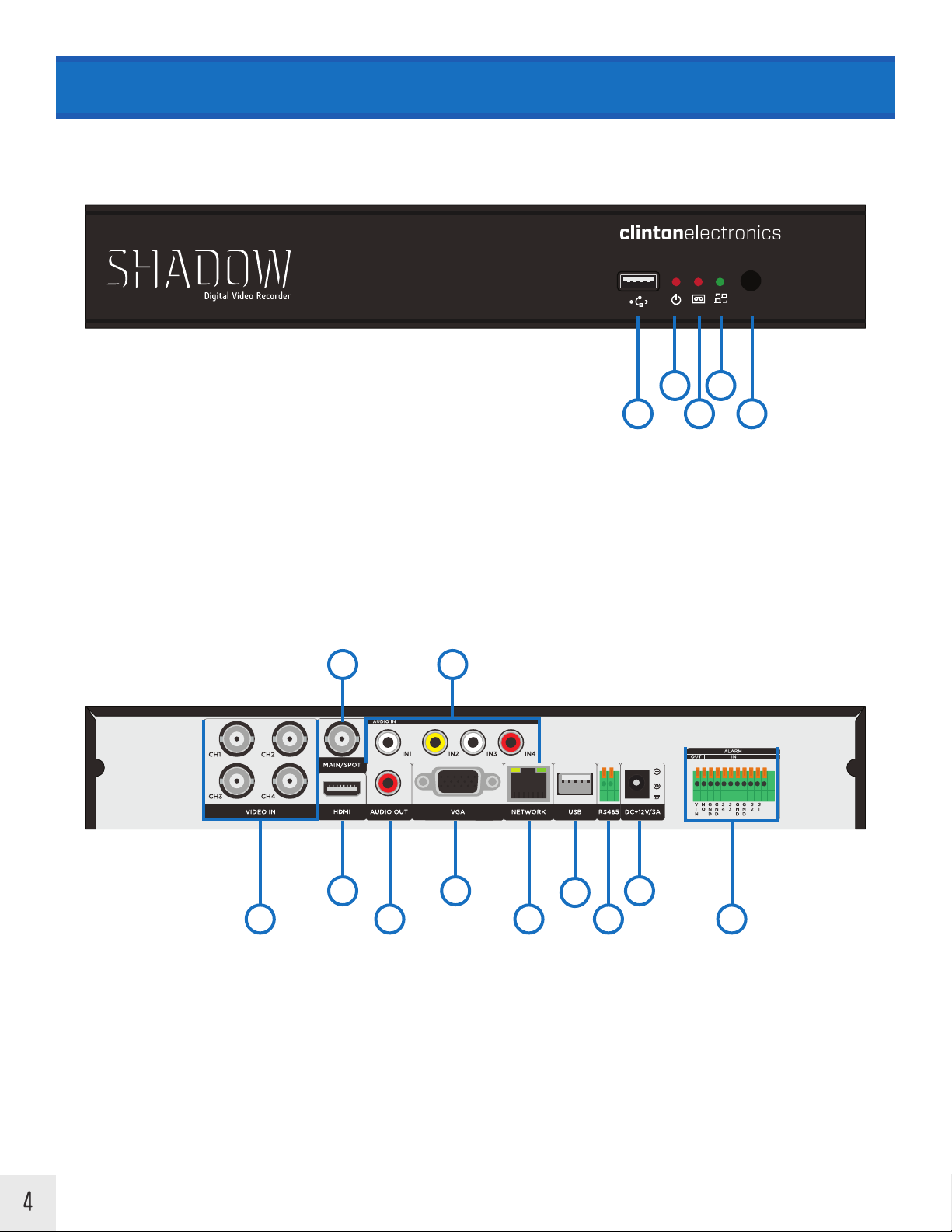
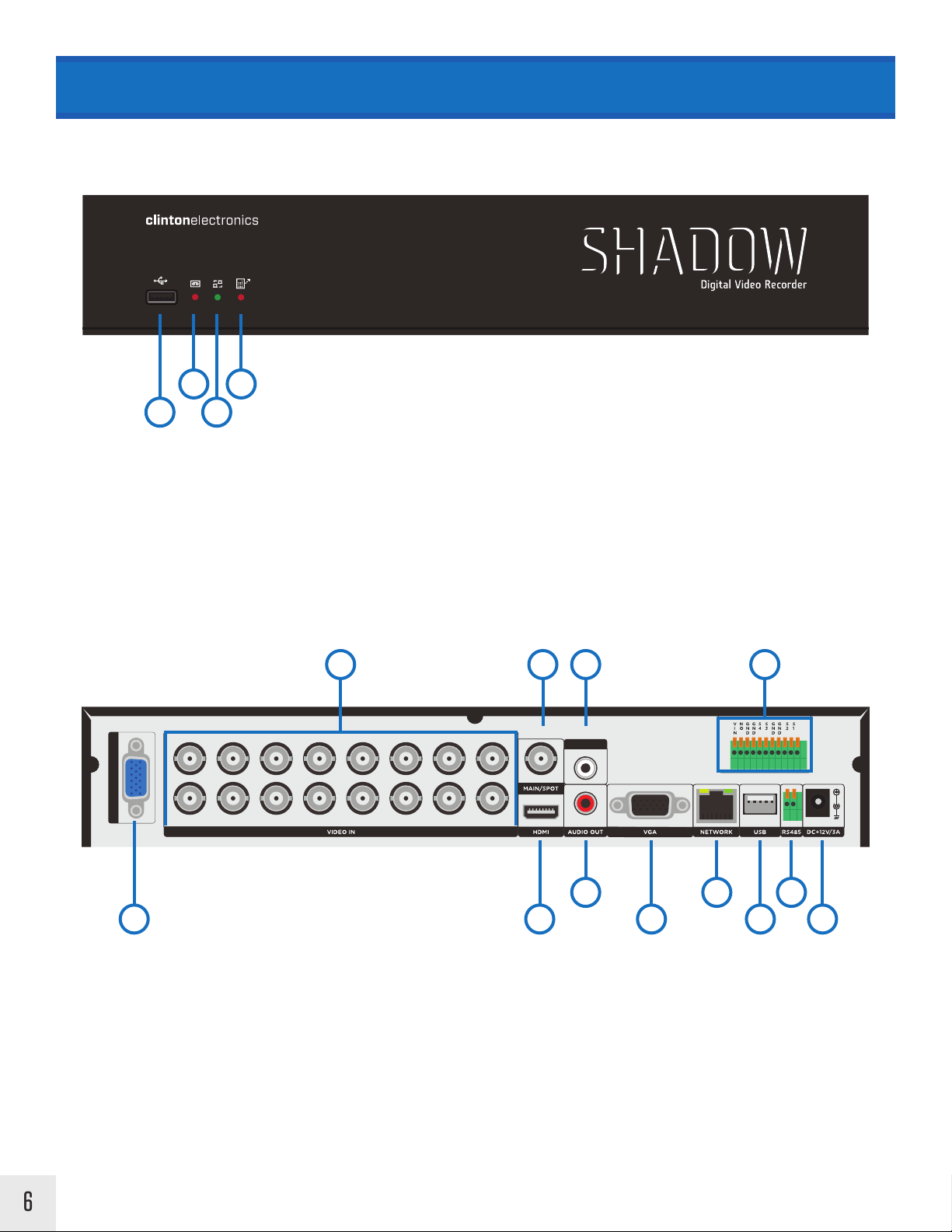
HARDWARE OVERVIEW > Shadow Series 4-Ch
FRONT
Late 2015 960H Version
1. USB Port - for Firmware Update and/or Video Backup
2. Power Indicator LED
3. Recording Indicator LED
4. Network Indicator LED
5. IR Sensor for Remote
2 5
BACK
2
4
1 5
3
1
1. BNC Camera Inputs
2. BNC Video Output - MAIN or SPOT
*MAIN or SPOT configured in DVR Settings
3. HDMI Video Output - MAIN
4. VGA Video Output - MAIN
5. RCA Audio Inputs
6. RCA Audio Output
43
6
7. RJ45 Network Connection
8. USB Port - Mouse
9. RS485
10. DC12V Power Input
11. Alarm Inputs/Outputs
8
7
10
9
11
4
Page 7
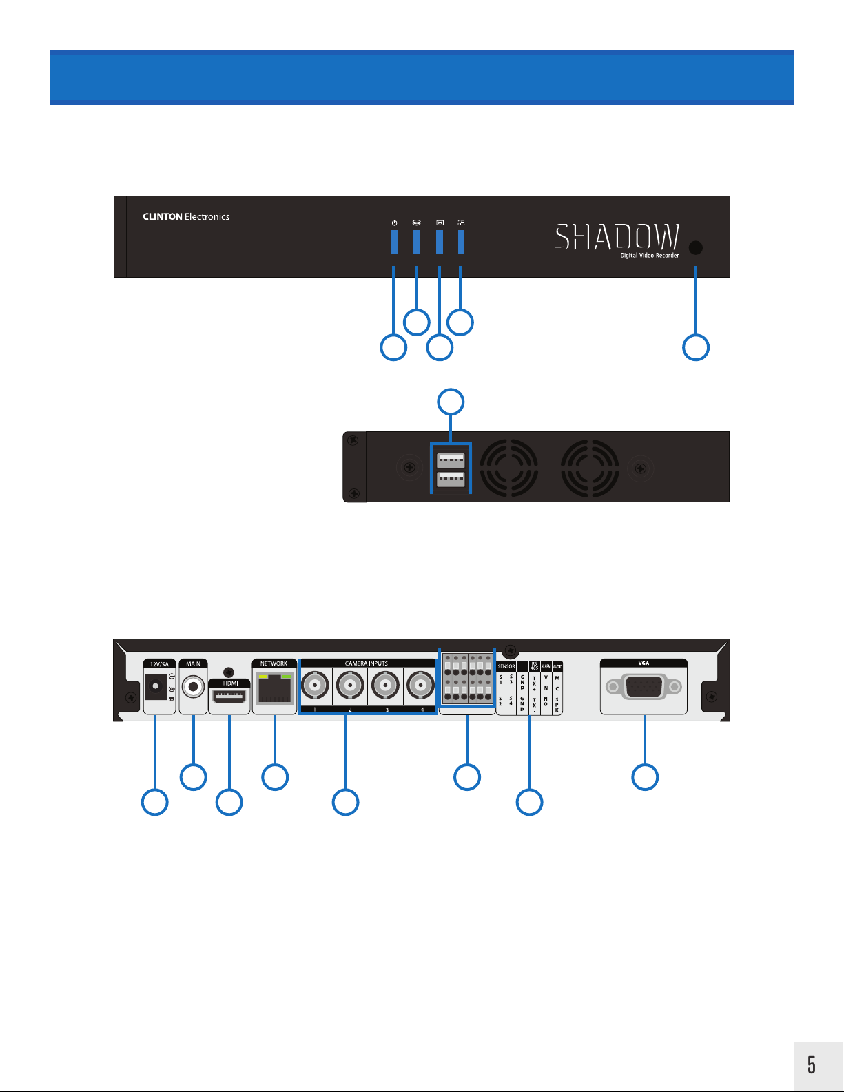
HARDWARE OVERVIEW > Shadow Series 4-Ch
FRONT
D1 (704x480) Version
1. Power Indicator LED
2. HDD Indicator LED
3. Recording Indicator LED
4. Network Indicator LED
5. IR Sensor for Remote
6. USB Ports:
Top - for Firmware Update and/or Video Backup
Bottom - for Mouse
BACK
2
1 5
4
3
6
SIDE
1 3
1. DC12V Power Input
2. RCA Video Output - MAIN
3. HDMI Video Output - MAIN
4. RJ45 Network Connection
82 4 6
5
5. BNC Camera Inputs
6. Sensor/Ground/RS485/Alarm/Audio Connections
7. Connection Diagram
8. VGA Video Output - MAIN
7
5
Page 8
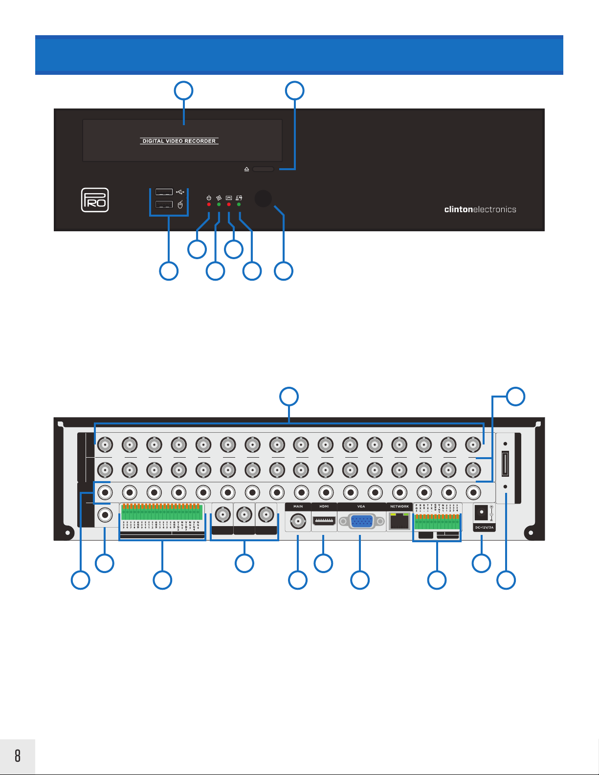
HARDWARE OVERVIEW > Shadow Series 8/16-Ch
FRONT
Late 2015 960H Version
2
1
1. USB Ports:
Top - for Firmware Update and/or Video Backup
Bottom - for Mouse
2. Recording Indicator LED
3. Network Indicator LED
4. IR Sensor for Remote
4
3
BACK (16-Ch Shown)
CH1
CH3
CH5
CH7
AUDIO IN (2-16)
CH2
CH4
CH6
CH8
2 3 5 10
CH9
CH11
CH13
CH10
CH12
CH14
CH15
CH16
AUDIO IN
IN1
ALARM
6 8 11
1
1. Audio Input (Channels 2-16, uses RCA to Multi-Pin Plug Adapter)
2. BNC Camera Inputs
3. BNC Video Output - MAIN or SPOT
*MAIN or SPOT configured in DVR Settings
4. HDMI Video Output - MAIN
5. RCA Audio Input (Channel 1)
6. RCA Audio Output
7. VGA Video Output - MAIN
8. RJ45 Network Connection
9. USB Port - for Mouse
10. Alarm Connection
11. RS485
12. DC12V Power Input
4 7 9 12
6
Page 9

HARDWARE OVERVIEW > Shadow Series 8/16-Ch
FRONT
2
4
D1 (704x480) Version
1
3
1. USB Ports:
Top - for Firmware Update and/or Video Backup
Bottom - for Mouse
2. Recording Indicator LED
3. Network Indicator LED
4. IR Sensor for Remote
BACK
DC+12V/5A NETWORK
3 5 9
MAIN
SPOT
CAMERA INPUTS
SENSOR
S1
S5
S3
S2
S6
S4
VGAHDMI
RS
ALARM
AUDIO
485
SP K
T X +
S7
M3
M1
VIN
2
1
GN D
T X -
S8
M4
M2
NO
2
1
1. DC12V Power Input
2. RJ45 Network Connection
3. RCA Video Output - Main
4. RCA Video Output - Spot
5. Camera Inputs (uses BNC to Multi-Pin Plug Adapter)
2 6 8
1 4 7
6. HDMI Video Output - Main
7. VGA Video Output - Main
8. Sensor/Audio/RS485/Alarm Connections
9. Connection Diagram
7
Page 10
HARDWARE OVERVIEW > Pro Series
960H - 3 Spot Monitor Version
FRONT
7 8
2
1 6
1. USB Ports:
Top - for Firmware Update and/or Video Backup
Bottom - for Mouse
2. Power Indicator LED
3. Internal Fan Indicator LED
4. Recording Indicator LED
4
3
5
5. Network Indicator LED
6. IR Sensor for Remote
7. CD-R/DVD-R Disc Drive
8. Disc Drive Eject Button
1 2
BACK (16-Ch Shown)
VIDEO
AUDIO
CH1
OUT IN
AIN1 AIN2 AIN3 AIN4 AIN5 AIN6 AIN7 AIN8 AIN9 AIN10 AIN11 AIN12 AIN13 AIN14 AIN15 AIN16
OUT IN
4 6 8 11
3 5 7 9 10 12
1. BNC Camera Inputs
2. BNC Camera Loop-Out/Outputs
3. RCA Audio Inputs
4. RCA Audio Output
5. Alarm Inputs/Outputs
CH3 CH4 CH5 CH6 CH7 CH8 CH9 CH10 CH11 CH12 CH13 CH14 CH15 CH16
CH2
IN OUT
ALARM
SPOT 1MAIN SPOT SPOT 2
RS-485
7. BNC Video Out - MAIN or SPOT
8. RJ45 Network Connection
9. USB Port - for Mouse
10. RS485 & Alarm Inputs/Outputs
11. DC12V Power Input
ALARM
eSATA
INOUT
6. BNC Video Out - SPOTS
12. e SATA P ort
8
Page 11

HARDWARE OVERVIEW > Pro Series
D1 - 3 Spot Monitor Version
FRONT
7 8
2
1 6
1. USB Ports:
Top - for Firmware Update and/or Video Backup
Bottom - for Mouse
2. Power Indicator LED
3. Internal Fan Indicator LED
4. Recording Indicator LED
4
3
5
5. Network Indicator LED
6. IR Sensor for Remote
7. CD-R/DVD-R Disc Drive
8. Disc Drive Eject Button
1
BACK (16-Ch Shown)
MAIN SPOT1
SPOT2 SPOT3
3 75 9 11 13 15
1. BNC Camera Inputs
2. BNC Camera Loop-Out/Outputs
3. BNC Video Out - MAIN
4. BNC Video Out - SPOTS
5. Power ON/OFF Switch
VIDEO IN
VIDEO OUT
VIDEO OUT
CH1 CH2
CH3 CH4 CH5 CH6 CH7 CH8 CH9 CH10 CH11
ALARM OUT ALARM IN
RS232
HDMIAUDIO
VGA
CH12 CH13 CH14 CH15 CH16
RS485
64 8 10 12 14
9. Alarm Input
10. HDMI Video Out - MAIN
11. RS232 Connection
12. VGA Video Out - MAIN
13. RS485 Connection
eSATA II
WAN
2
6. Power Input
7. Alarm Output
8. Audio Input (uses RCA to Multi-Pin Plug Adapter)
14. eSATA Port
15. RJ45 Network Connection
9
Page 12
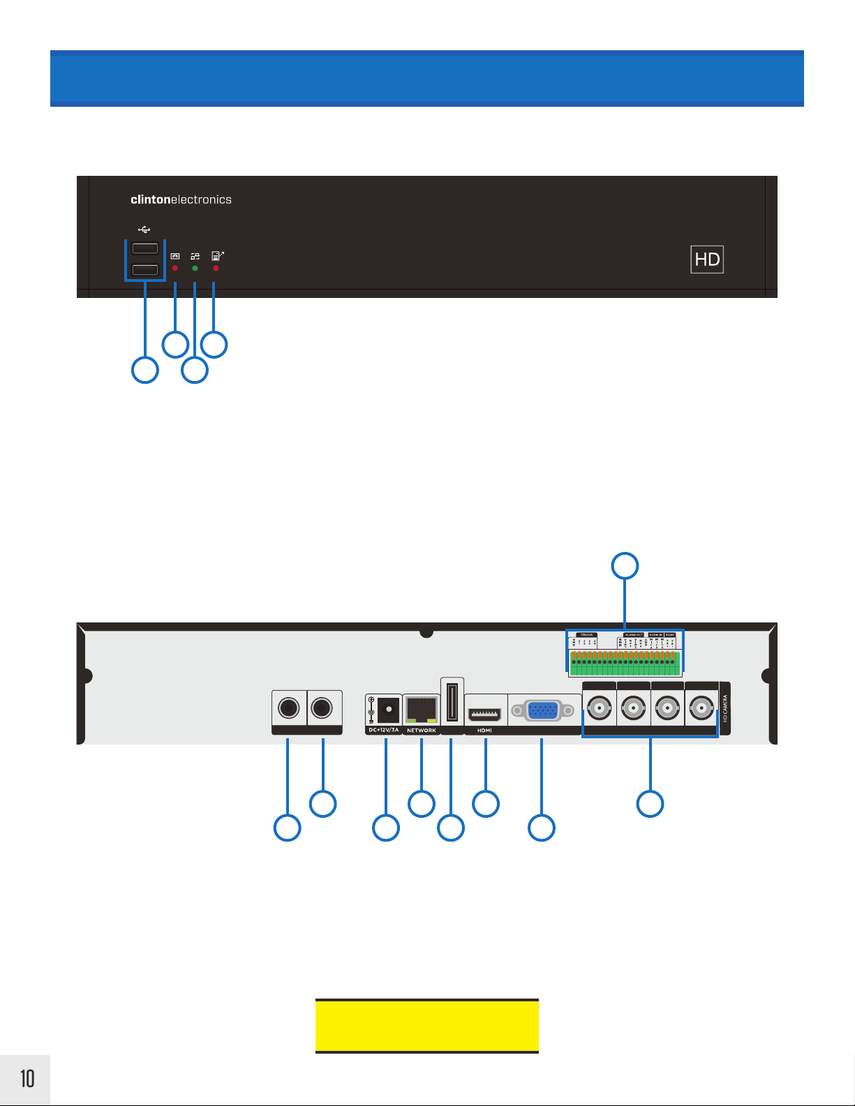
HARDWARE OVERVIEW > HD Series 4-Ch
FRONT
2
4
1
1. USB Ports:
Top - for Firmware Update and/or Video Backup
Bottom - for Mouse
2. Recording Indicator LED
3. Network Indicator LED
4. IR Sensor for Remote
3
BACK
9
CH1 CH2 CH3 CH4
HD-SDI INPUTSMIC1 SPK. VGAeSATA
10
1. RCA Audio Input
2. RCA Audio Output
3. DC12V Power Input
4. RJ45 Network Connection
5. eSATA Por t
2 4 6 8
1 3 5 7
6. HDMI Video Out - MAIN
7. VGA Video Out - MAIN
8. BNC Camera Inputs (HD-SDI)
9. Sensor / Alarm / Audio / RS485 Connections
For use with HD-SDI cameras only.
Standard/Analog cameras will not
function with this DVR.
Page 13
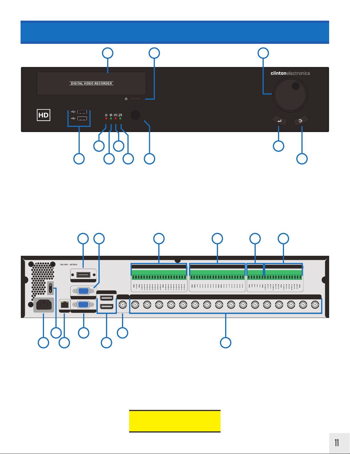
HARDWARE OVERVIEW > HD Series 16-Ch
FRONT
7 98
2 10
1 6
1. USB Ports:
Top - for Firmware Update and/or Video Backup
Bottom - for Mouse
2. Power Indicator LED
3. Internal Fan Indicator LED
4. Recording Indicator LED
4
3 11
5
6. IR Sensor for Remote
7. CD-R/DVD-R Disc Drive
8. Disc Drive Eject Button
9. Jog Wheel
10. Enter
5. Network Indicator LED
11. Back
4 10 11 13125
BACK
AUDIO ALARM IN ALARM OUTRS-485
eSATA
RS232
HDMI OUT
NETWORK
2 6 8
1 3 7 9
1. Power Input
2. Power ON/OFF Switch
3. RJ45 Network Connection
4. eSATA Por t
SDI OUT
MAIN
SPOT SPOT SDI CH1 SDI CH2 SDI CH3 SDI CH4 SDI CH5 SDI CH6 SDI CH7 SDI CH8
9. BNC Camera Inputs (HD-SDI only)
10. Audio Connections
11. Alarm Inputs
12. RS485 Connections
SDI IN
SDI CH9 SDI CH10 SDI CH11 SDI CH12 SDI CH13 SDI CH14 SDI CH15 SDI CH16VGA
5. RS232 Connection
6. VGA Video Out - MAIN
7. HDMI Video Out - MAIN top, SPOT bottom
8. BNC Video Out - SPOT (HD-SDI only)
13. Alarm Outputs
For use with HD-SDI cameras only.
Standard/Analog cameras will not
function with this DVR.
11
Page 14
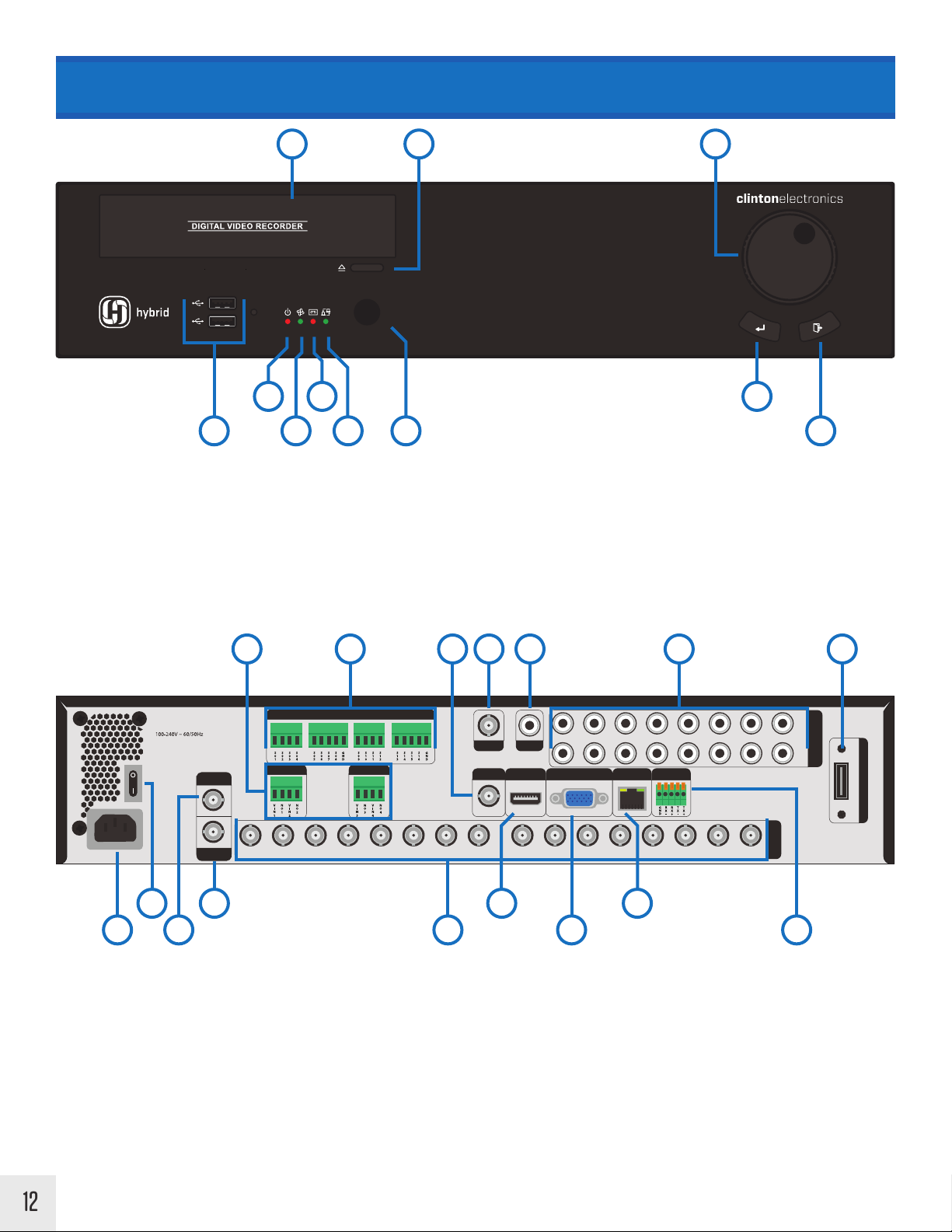
HARDWARE OVERVIEW | Hybrid Series 16CH
FRONT
7 98
2 10
1 6
1. USB Ports:
Top - for Firmware Update and/or Video Backup
Bottom - for Mouse
2. Power Indicator LED
3. Internal Fan Indicator LED
4. Recording Indicator LED
4
3 11
5
6. IR Sensor for Remote
7. CD-R/DVD-R Disc Drive
8. Disc Drive Eject Button
9. Jog Wheel
10. Enter
5. Network Indicator LED
11. Back
5 86 9 14 15 16
BACK
ALARM IN
AIN1
AIN2
AIN3
AIN4
AIN12
RS 485
AIN5
AIN13
AUDIO
SPOT
OUT
SPOT
9 - 16
SPOT
1 - 8
ALARM OUT
CH1 CH2 CH3 CH4 CH5 CH6 CH7 CH8 CH9 CH10 CH11 CH12 CH13 CH14 CH15 CH16
ALARM OUT
MAIN
HDMI VGA NETWORK
AIN9
AIN10
AIN11
2 4 10 12
1 3 7 11 13
1. Power Input
2. Power ON/OFF Switch
3. BNC Video Out - SPOT (Channels 9-16)
4. BNC Video Out - SPOT (Channels 1-8)
9. BNC Video Out - SPOT (Channels 1-16
10. HDMI Video Out - MAIN
11. VGA Video Out - MAIN
12. RJ45 Network Connection
VIDEO IN
AUDIO IN
AIN8
AIN16
eSATA
AIN6
AIN7
AIN14
AIN15
12
5. Alarm Outputs
6. Alarm Inputs
7. BNC Camera Inputs (HD-SDI & Analog)
8. BNC Video Out - MAIN
13. RS485 Connections
14. RCA Audio Output
15. RCA Audio Inputs
16. eSATA Port
Page 15
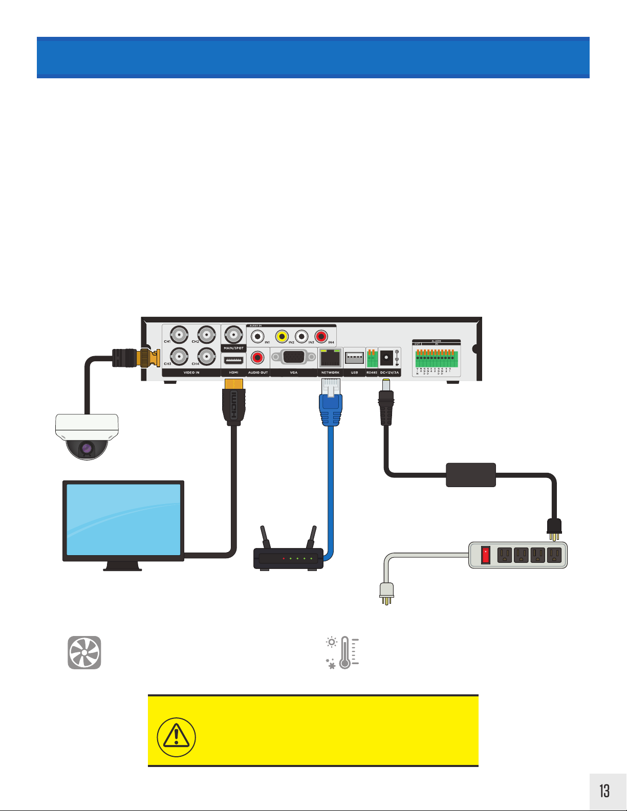
CONNECTING YOUR DVR
1. Connect coaxial cable from cameras to the desired channel on the back of the DVR.
2. Plug in an ethernet/CAT5 cable to the Network port on the back of the DVR. *If planning to network the DVR
3. Connect any RS485, Alarm or Audio connections.
4. Choose the desired main monitor connection; VGA / BNC / HDMI.
5. Plug the power cord into the back of the DVR.
6 . Plug the cord from the power supply into an appropriate surge protector.
7 . If your DVR has a Power ON/OFF switch - turn the DVR on. DVRs without a power switch will power ON automatically
once the power has been connected.
Clinton DVRs come pre-configured to automatically record video.
Basic DVR Connection Diagram
DVR
Camera
Monitor
Ensure there is adequate ventilation around
the DVR and do not cover or block the fan
and/cooling vents. The DVR can over-heat
if these are blocked.
NOTICE
It is strongly recommended to plug the DVR power supply
into a surge protector.
DVR Power Supply
Surge ProtectorModem/Router
Do not install the DVR into an environment
that is exposed extreme temperates; attic/
walk-in freezer. Do not install the DVR on
top or near equipment that generates heat.
A surge protector will help protect the DVR from damage
caused by unwanted surges/spikes in voltage and lightning.
13
Page 16
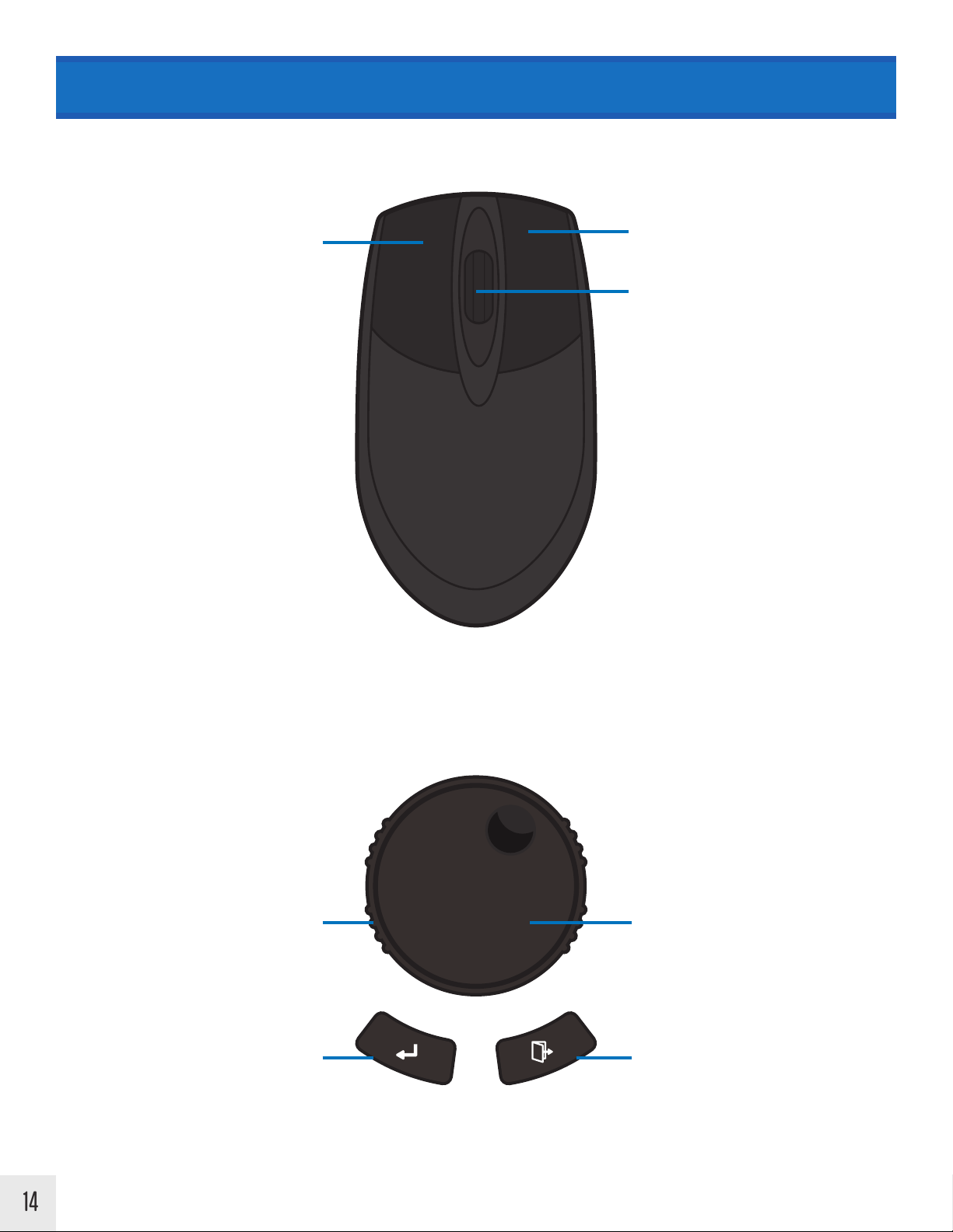
MOUSE & JOG WHEEL OVERVIEW
Image may vary from actual mouse supplied with the DVR.
Select Menu Options
Left Click
Click desired camera image to display full
screen, click again to return to Multiplex view
Right Click
Access the menu screen
Scroll Wheel
Digital Zoom In / Zoom Out when displaying a
camera view
Use the Jog Wheel when a Mouse or Remote is not available. The Jog Wheel is currently available only on the CEHDV16 & CE-HY16 model DVRs.
Use to navigate through DVR menus
Outer Ring
Turn & hold Left or Right to Fast Forward /
Reverse during playback
Releasing during playback pauses video
Enter
Enters the selected menu item
Jog Wheel
Use to navigate through DVR menus
Turn & hold Left or Right to search frame by
frame during playback.
Releasing during playback pauses video.
Esc/Exit
Backs out of current selection
14
Page 17
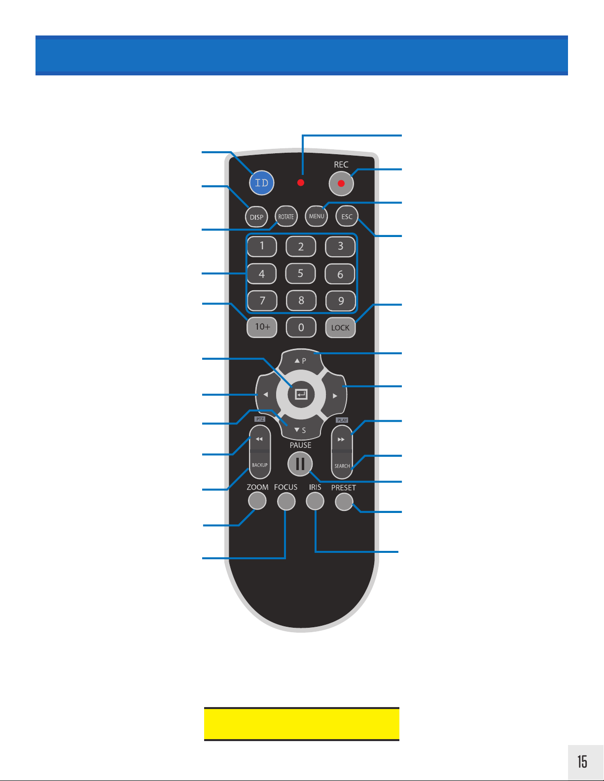
REMOTE CONTROL OVERVIEW
Use the buttons on the remote to quickly jump to DVR menu options, change camera views and more.
One remote can control up to 20 DVRs.
LED
Two digit remote control code from 00 to 19
ID
Display
Cycle through the various Multiplex Views
Illuminates red when a button is pressed
Record
Manual record
Menu
Access the menu screen
Cycle camera/channel of Multiplex View
Rotate
Number Keys
Use to select a specific camera (1-9) quickly
10+
Use to select a specific camera (10-16) quickly
ex:: Press the 10+ button, then 0 to select
camera 10.
Enter
Enters the selected menu item
Left Direction Key / Reverse
Left arrow / Reverse
Down Direction Key / S
Down arrow / Smart Play
Fast Reverse / PTZ
Quick reverse search / Open PTZ Menu
Backup
Open manual backup menu
Zoom (PTZ)
Zoom mode when PTZ is connected
Esc
Backs out of current selection
Lock
Quick User/Admin Logout
Up Direction Key / P
Up arrow / Panorama Play
Right Direction Key / Play
Right arrow / Play
Fast Forward / Play
Fast Forward / Play
Search
Open search menu
Pause
Pause live or recorded footage
Preset (PTZ)
Cycle through PTZ presets when PTZ is
connected
Focus mode when PTZ is connected
Focus (PTZ)
ID
Two digit remote control code from 00 to 19 (Default code is 00). Hold down ID and press two digits, ex: 01, to change ID to 1. ID code should
match DVR ID (Unit Address). The DVR ID can be found/changed in the General/System menu. A single remote control can be used to control up
to 20 DVRs.
Iris (PTZ)
Iris mode when PTZ is connected
Pressing 1024768 + ENTER on the number
pad will reset the screen resolution.
15
Page 18
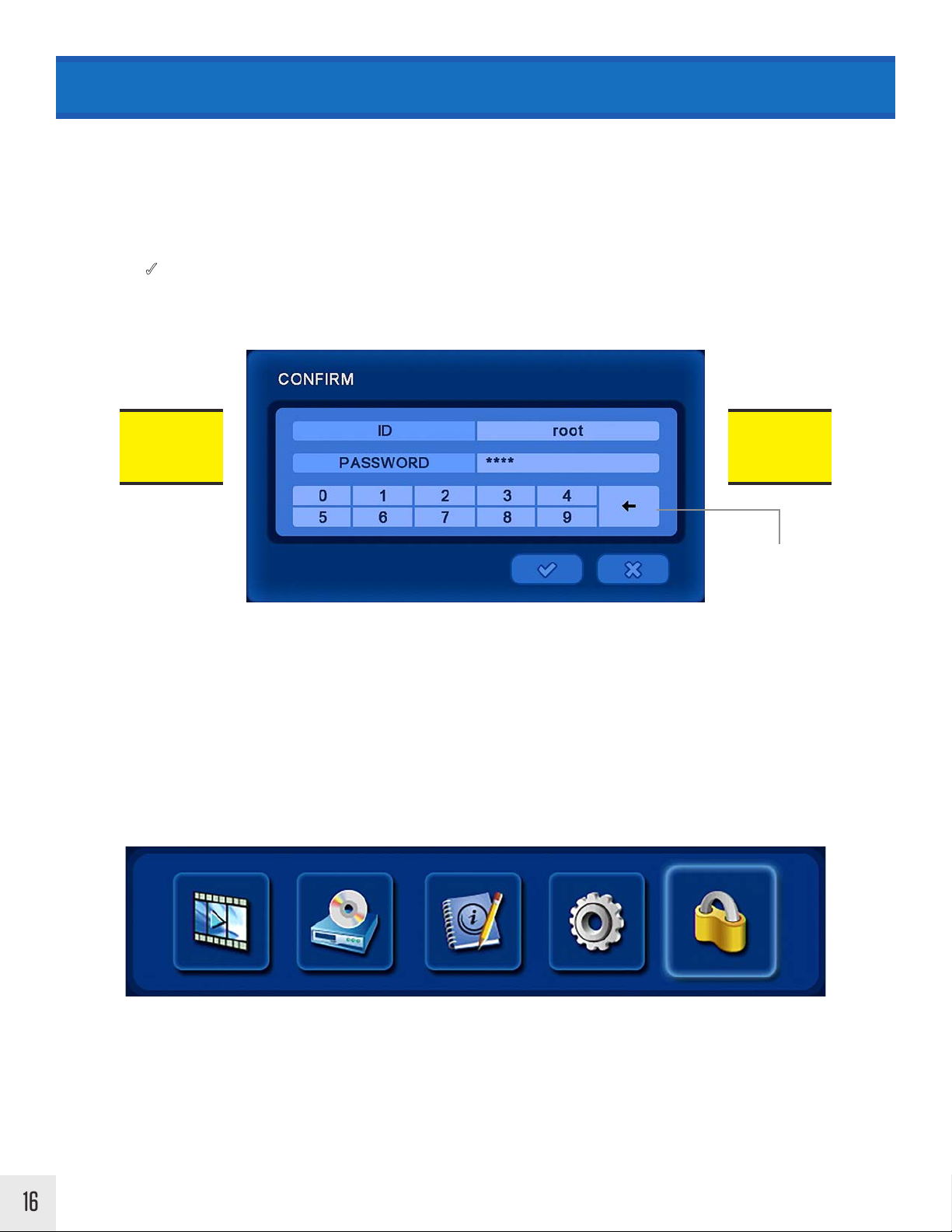
LOGIN & LOGOUT
Login Box
A user ID and Password is requited to access any DVR controls.
The default ID is “root” and the default password is “1111”.
Click the 3 [Check Mark] with the mouse cursor or press the ENTER button on the remote to proceed.
Default
ID:
root
To edit User ID and Password information, please refer to SETUP/ACCOUNT.
Default
Password:
1111
Delete/Backspace
Log-Out
Select the Log-Out icon (LOCK icon found at the top of the screen) to exit from your account. After a certain period of
inactivity, the DVR will automatically log out the user. The automatic log out (Menu Timeout) can be adjusted in Setup
Menu > General > System > Menu Timeout.
16
SettingsSearch Status LOG-OUTBackup
Page 19
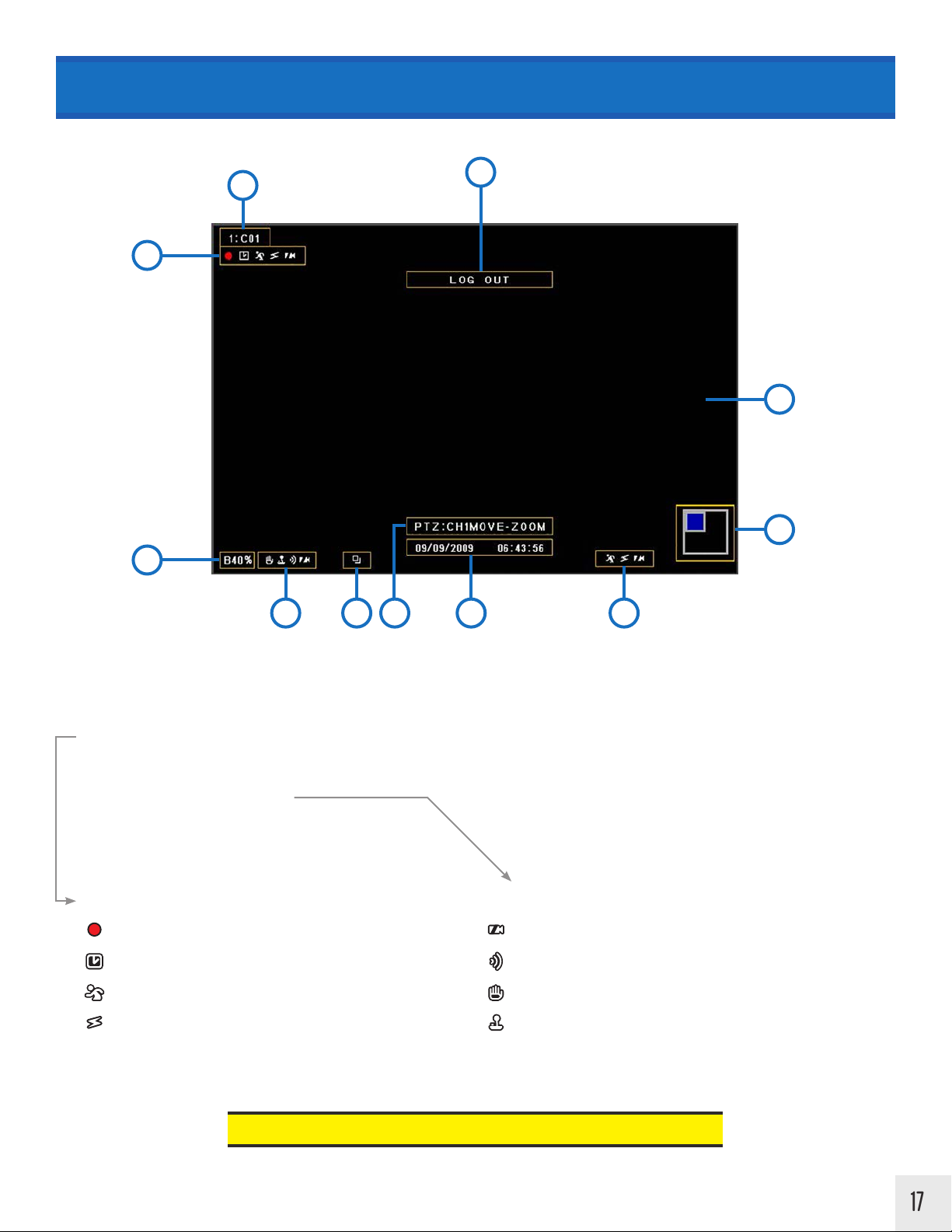
LIVE VIEW SCREEN LAYOUT
2
1
3
11
10
4
5 6 7 8 9
1. Execution Information Message
2. Camera Name
3. Record Status Icons
4. Backup Progress Status %
5. Current Channel Information Icons
6. Sequence Icon: When screen image is cycled continuously
Record Status Icons:
Record Icon: Shows when recording is active.
Time Icon: Shows when time (schedule) record mode is active.
Motion Icon: Shows when motion occurs.
Sensor Icon: Shows when the external sensor is triggered.
7. PTZ Control Information
8. Current Date and Time
9. Current Event Information
10. Zoom 2x / 4x Location
11. Live Screen Area
Current Channel Information Icons:
Video-Loss Icon: Shows when no video input is sensed.
Audio Icon: Shows when audio occurs within the live screen.
Freeze Icon: Shows when live view is paused.
PTZ Icon: Shows when in PTZ mode
If the Record Icon is BLUE, the DVR is in the Search/Playback mode.
17
Page 20
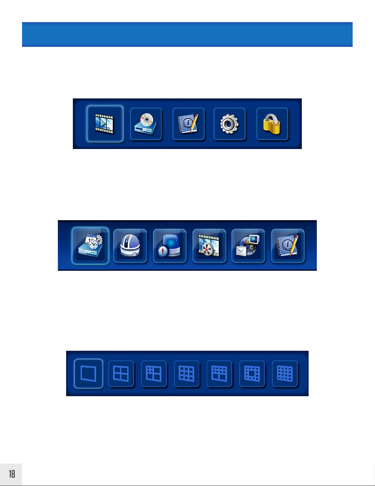
MENU ICONS EXPLAINED
Top Menu
In the live screen, press the UP button on the remote control, or move the mouse cursor over the top area of the
screen. The top menu will automatically appear.
Search Status Settings Log-Out
Backup
Main Menu (Middle)
Press the MENU button on the remote control, or right click with the mouse - then choose Main Menu.
Setup Camera Event Record Network Info
Bottom Menu - Live View
In the live screen, press the DOWN button on the remote control, or move the mouse cursor over the bottom area of
the screen. The bottom menu will automatically appear.
18
Full
Screen
Selecting one of these menu options will change the Multiplex View (the way the live camera views are arranged).
Depending on the model of DVR, not all Multiplex View options will be available. Example, a 4 Channel DVR will not
be able to display 16 camera views.
Quad
Screen
4-Mini
3-Large
9
Cameras
8-Mini
2-Large
12-Mini
1-Large16Cameras
Page 21
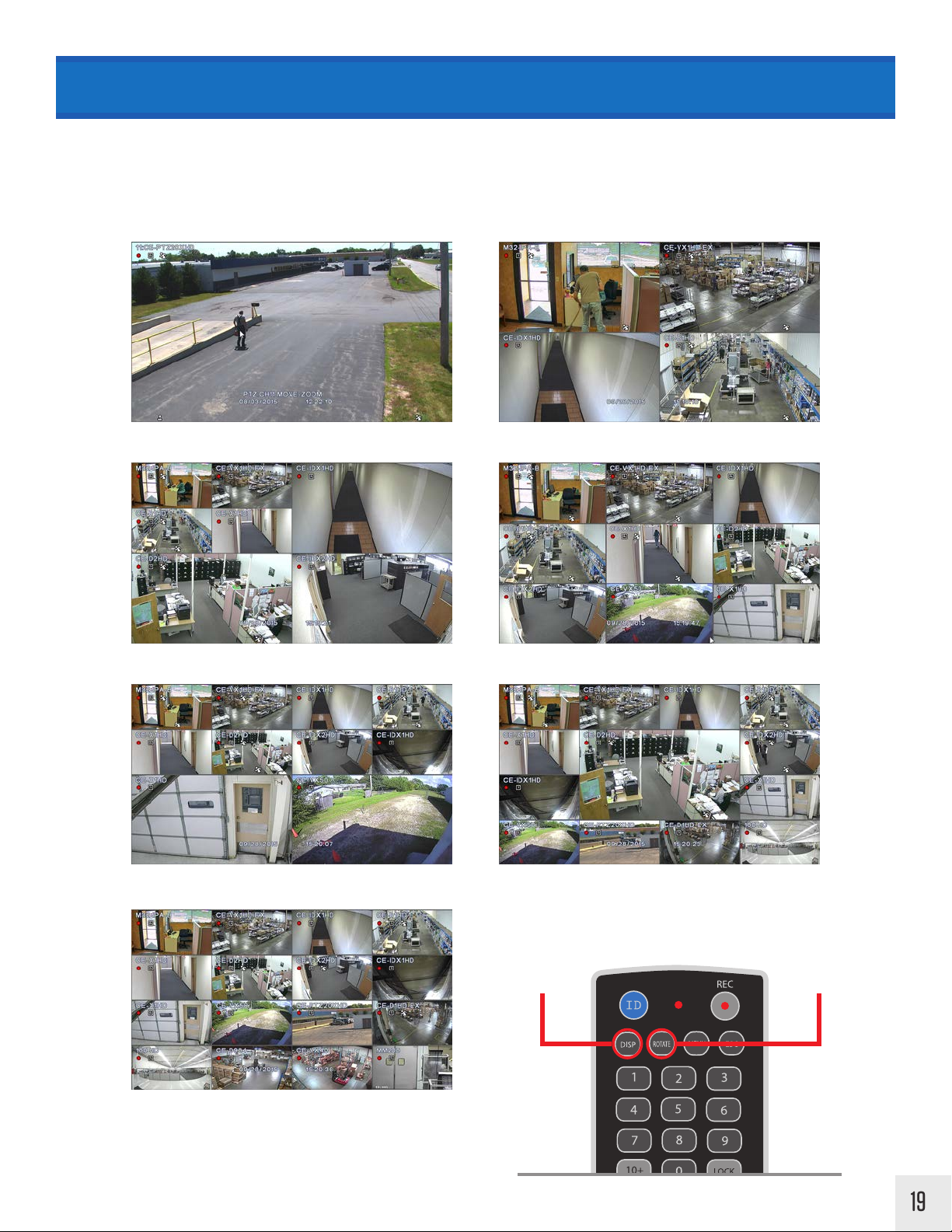
MULTIPLEX VIEWS
From the bottom menu, select one of the options to change the way the camera images are arranged, or press the DISP
(Display) button on the remote control.
To change the order of the cameras of displayed in the chosen Multiplex View (from the bottom menu), click the same
icon again or press ROTATE on the remote control..
Full Screen Quad Screen
4-Mini / 3-Large 9 Cameras
8-Mini / 2-Large 12-Mini / 1-Large
Press DISP to
change Multiplex
View
Press ROTATE to
change camera
order
16 Cameras
19
Page 22

MENU SCREENS EXPLAINED
Some menu screens have the ability to apply settings to every camera/channel simultaneously rather than individually. This saves time if each camera/channel setting is desired to be the same. When a + is found at the top of the
column; ACTIVE + / LEVEL + / AREA +, clicking on the item will open a menu screen that will apply those settings to
every camera in the column.
Some menu options are not editable and are indicated by having a darker color background.
Click the 3 [Check Mark] button to confirm changes made. Click the X button or let the menu screen timeout to cancel
any changes made to the DVR.
Click an item with a
+ to apply settings to
every camera.
20
Click to confirm
changes
Darker colored boxes
are not editable.
Click to cancel
changes
Page 23
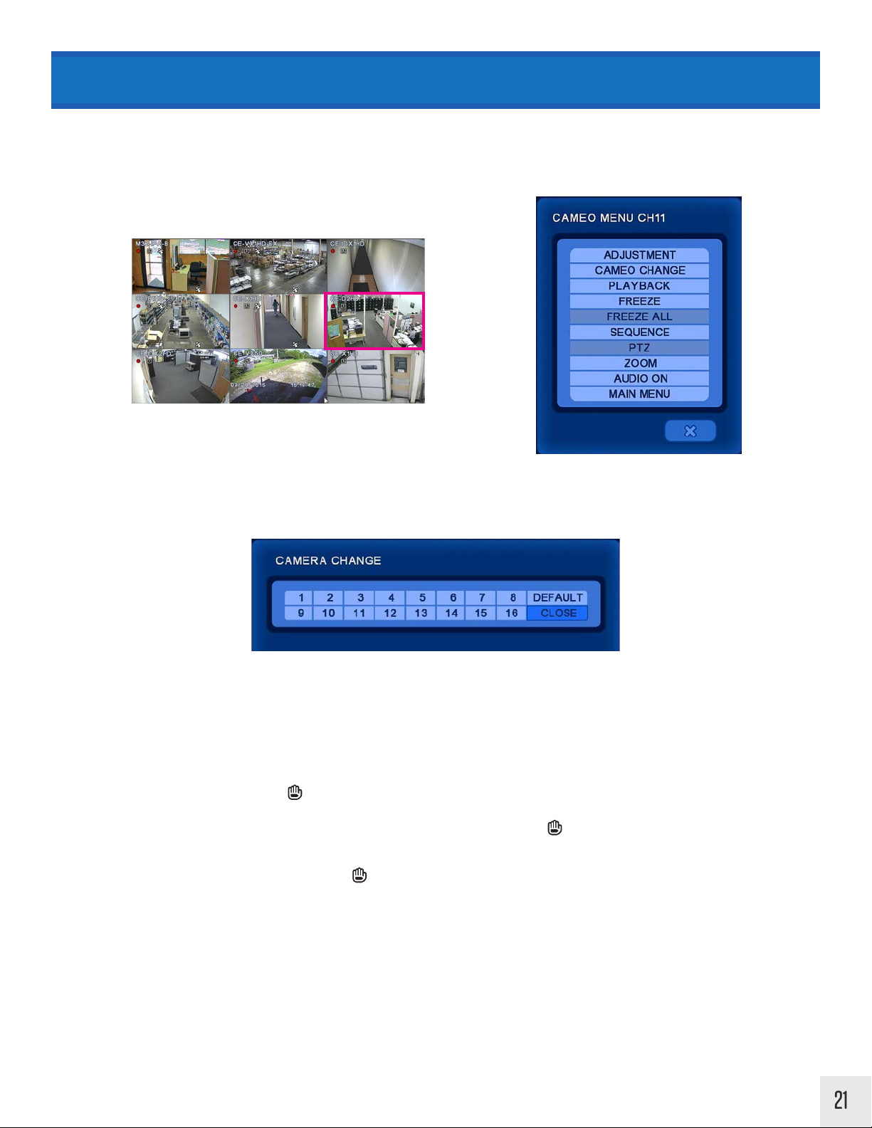
CAMEO MENU
In the live screen, right-click on the camera to adjust the settings. With the remote control, press the ENTER button to
bring up the pink-frame channel selector. Press the ENTER button again to bring up the menu for the selected channel. From this menu the adjustment menu ca be accessed for the selected camera channel.
Right
Click
Adjustment: Adjust brightness, contrast, saturation, and hue for live or recording view. *This feature will be added
to HD-SDI based DVRs at a later date.
Cameo Change: Swap the position of the selected camera with the position of another camera.
• Right click on the desired new location of the camera, select CAMEO CHANGE.
• Next select the existing camera you wish to move.
• To move the cameras back to their original positions, right click, select CAMEO CHANGE,
then select DEFAULT.
Playback: Playback the last recording from the selected camera.
Freeze: Freezes the live screen. A icon will be present within the channel’s frame when image is in freeze mode. To
unfreeze, select FREEZE again under the menu. Cameras will unfreeze when cameras are swapped positions, cameras
are attached or detached from the DVR, or other actions are executed. (The icon may remain on screen when this
happens- To remove, select FREEZE again from the menu).
Freeze All: Freezes all live camera images. A icon will be present when image is in freeze mode. To unfreeze, select
FREEZE ALL again under the menu.
Sequence: Cycle through live screen channels.
Cameo Sequence: Cycle through live attached camera channels. Note: All screens except the 16 Camera screen will
sequence any channel selected with cameras not shown on screen, if more cameras are connected than are shown on
the screen.
Page Sequence: Cycle through all channels (regardless of camera signal). Note: 1, 4, 9 camera screens only. Not
available on 4Ch Shadow.
21
Page 24
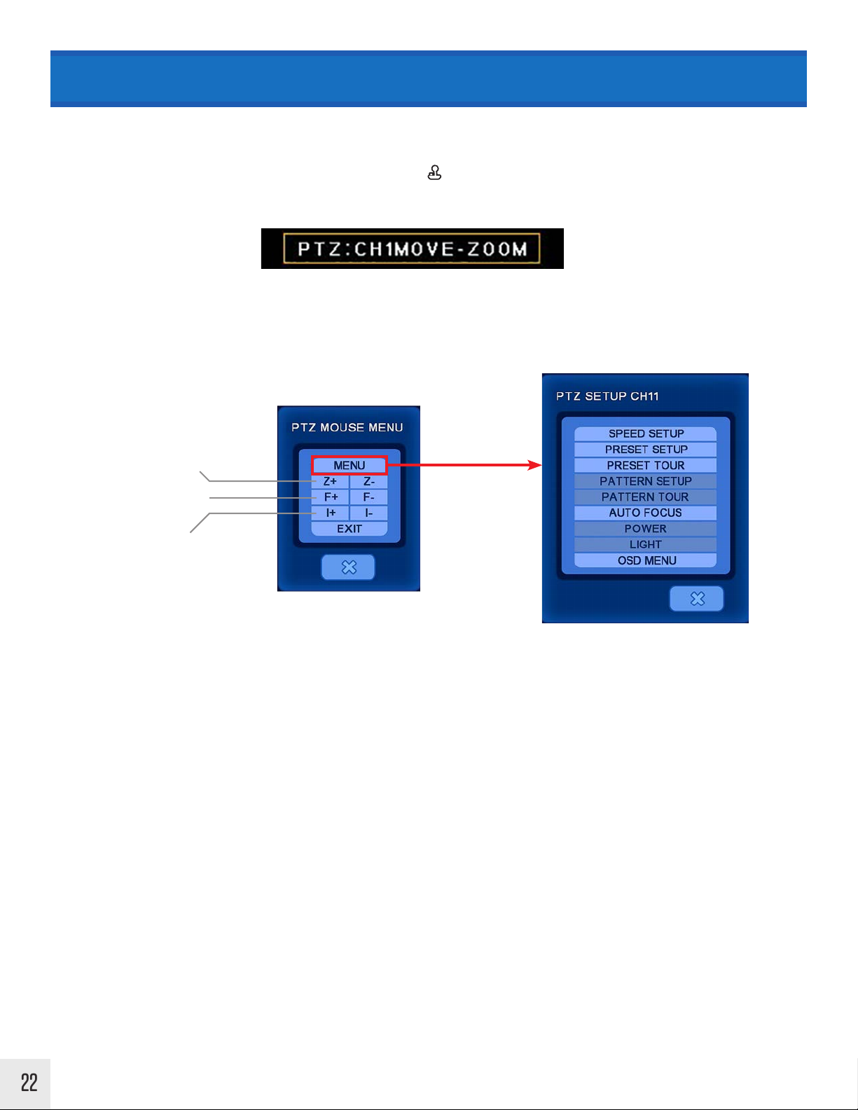
CAMEO MENU > PTZ Control
PTZ: Select to control an attached PTZ camera. A PTZ camera must be connected in order to access this menu item.
After selecting PTZ from the Cameo Menu - The PTZ icon will appear in the lower left corner of the screen when
within PTZ mode. The following will appear on the bottom center of the screen after selecting PTZ from the main
menu.
Using Mouse:
Right clicking the mouse button will bring up the following control screen for Menu, Zoom, Focus, and Iris controls.
Left click on the buttons to adjust your PTZ camera.
ZOOM Control
FOCUS Control
IRIS Control
Using Remote Control:
Press the enter button when the PTZ selection is highlighted on the camera menu.
Menu: In PTZ mode, press the Menu button to bring up additional PTZ controls such as Preset Setup, Auto Focus, etc.
Pan & Tilt: In PTZ mode, press the arrow buttons.
Zoom: In PTZ mode, press the following: Zoom In- Fast Reverse Button Zoom Out- Fast Forward Button
Focus: In PTZ mode, press the Focus button, then the following: Wide- Fast Reverse Button / Tele- Fast Forward
Button
Iris: In PTZ mode, press the Iris button, then the following: Open- Fast Reverse Button Close- Fast Forward Button
22
Page 25
CAMEO MENU
Cameo Menu / PTZ / MENU
Speed Setup: Set the PTZ camera speed (1 to 8).
Preset Setup: Set the preset position. If the position setup is saved, the PTZ camera will be directed to the set
position by preset number.
Preset Tour: 6 dierent preset lists can be created. If the created preset lists are set to “ON”, the PTZ will run the
preset tour.
Pattern Setup: Pattern can be created by movement, zoom, focus, and iris. After pressing the BEGIN button,
adjust the PTZ camera’s position or zoom and press the END button. All directions (up, down, left, and right),
zoom and iris settings are recorded. If using Clinton PTZs; set to Pelco Protocol to make this function available.
Pattern Tour: The PTZ camera moves according to the saved pattern.
Auto Focus: Turn On/O auto focus. This feature is not available when using Clinton PTZ cameras.
Power: Turn On/O power. This feature is not available when using Clinton PTZ cameras.
Light: Turn On/O light. This feature is not available when using Clinton PTZ cameras.
OSD Menu: Turn On/O OSD. This feature is not available when using Clinton PTZ cameras.
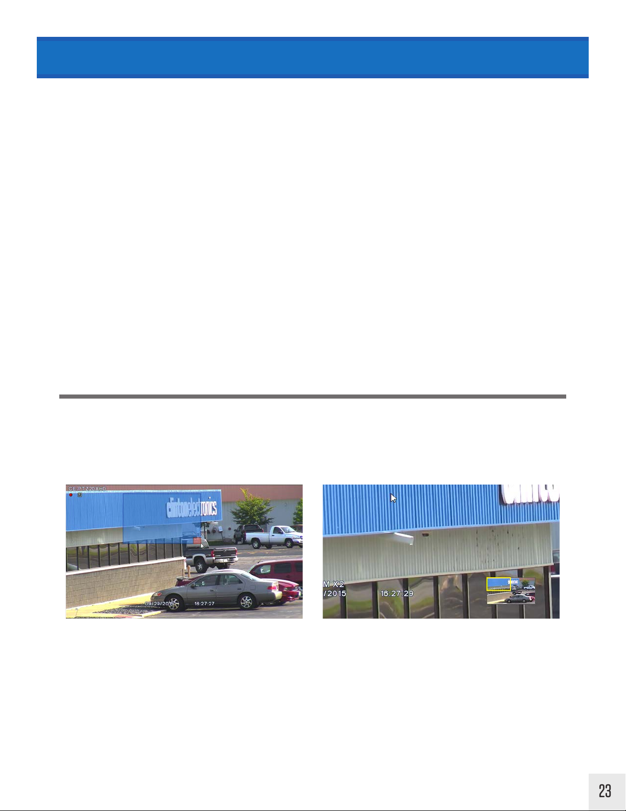
ZOOM: After clicking on Zoom, a red box will appear in the middle of the screen. With the mouse - Left click and hold
down the mouse button to draw a zoom selection box. The selection will be highlighted in blue. Releasing the left
mouse button will zoom to the selected area. The position of the zoomed selection is indicated on the PIP window in
the lower right corner of the screen.
A small zoom selection will zoom to 4X.
A larger zoom selection will zoom to 2X.
The YELLOW box in the PIP window shows
where the zoomed area is in relation to the
overall camera image.
AUDIO ON: Turn the audio on for the selected channel. This will only be used when an audio device is attached to
the associated channel.
23
Page 26
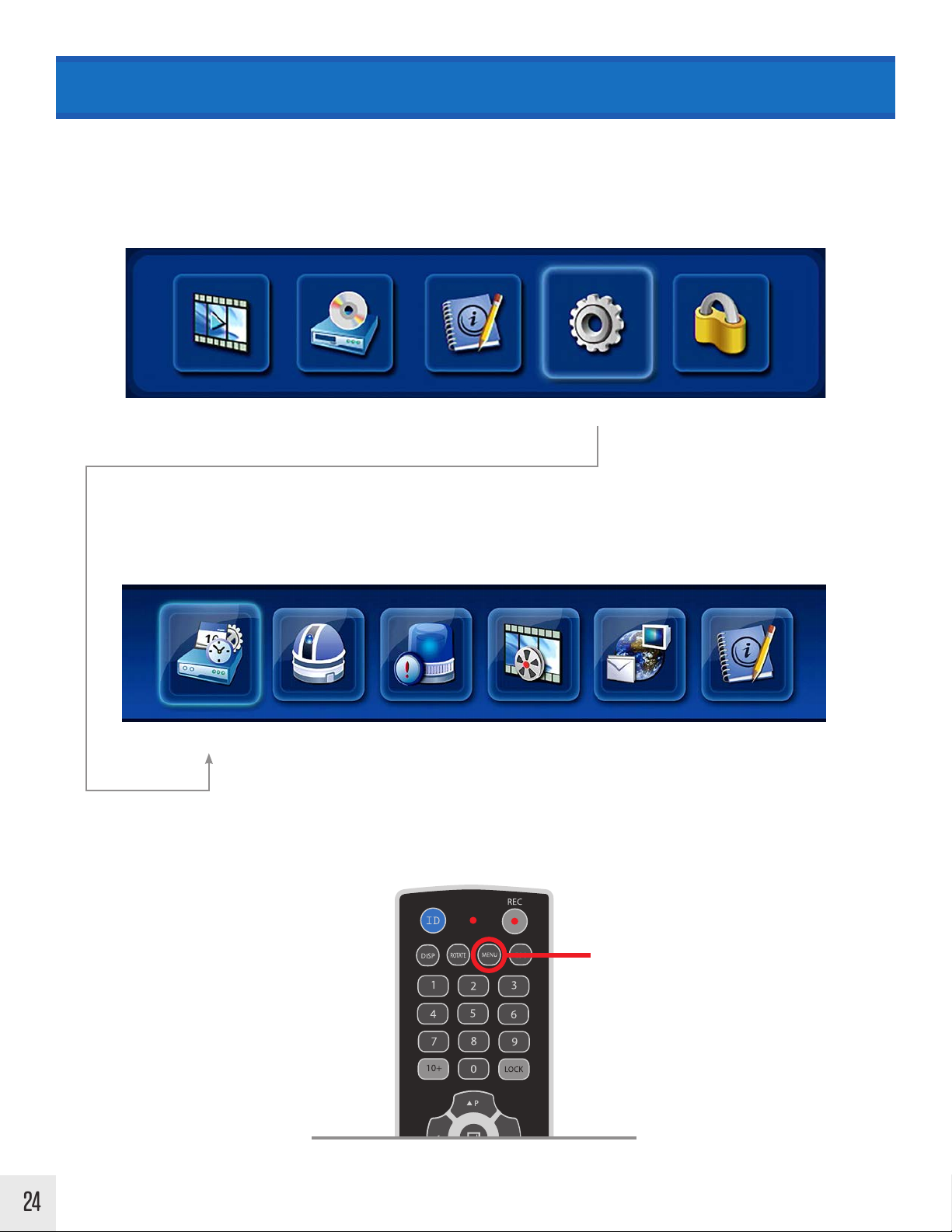
SETUP MENU
The SETUP menu can be accessed by pressing MENU on the remote control; by moving the mouse cursor to
the top of the screen, clicking on the Settings icon, then clicking on the Setup icon; or by right clicking with
the mouse, then selecting Main Menu.
Top Menu
SettingsSearch Info Log-OutBackup
Main Menu (Middle)
SETUP Camera Event Record Network Info
Press MENU to display
the main menu screen
24
Page 27
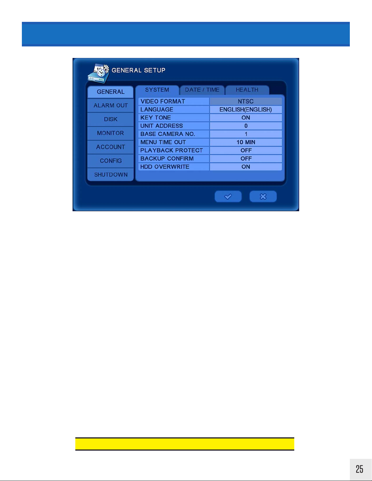
SETUP MENU > General > System
VIDEO FORMAT: Not adjustable from the DVR menu.
LANGUAGE: Select the language: English, German, French, Spanish, Japanese, Chinese, Italian,
Russian, Dutch, or Korean.
KEY TONE: Turn On/O the buzzer key tone.
UNIT ADDRESS: Set the DVR’s ID number- This ID can be used when multiple DVRs are in the same
location to control the DVRs individually with a single remote control. The DVR ID code must match
the ID code from the remote.
BASE CAMERA NO: Set the beginning number of a camera. This can be useful to determine which
camera is shown on-screen when multiple DVRs are being used.
Example: If set to “17”, the first camera number will be 17. If 16 cameras are attached, the camera
numbers will range from 17 to 32.
MENU TIMEOUT: Set the length of time the menu will show on-screen before it disappears.
PLAYBACK PROTECT: Prohibit the playback of past video. (Select from 0-99 days)
Example: If set to 3 days, the DVR will only save 3 days worth of data before it is overwritten.
BACKUP CONFIRM: Enable this setting to require the Admin login before you can backup.
HDD OVERWRITE: Select On/O to overwrite recorded video when the Hard Drive is full.
If HDD Overwrite is set to OFF, recording will stop when the HDD is full.
25
Page 28
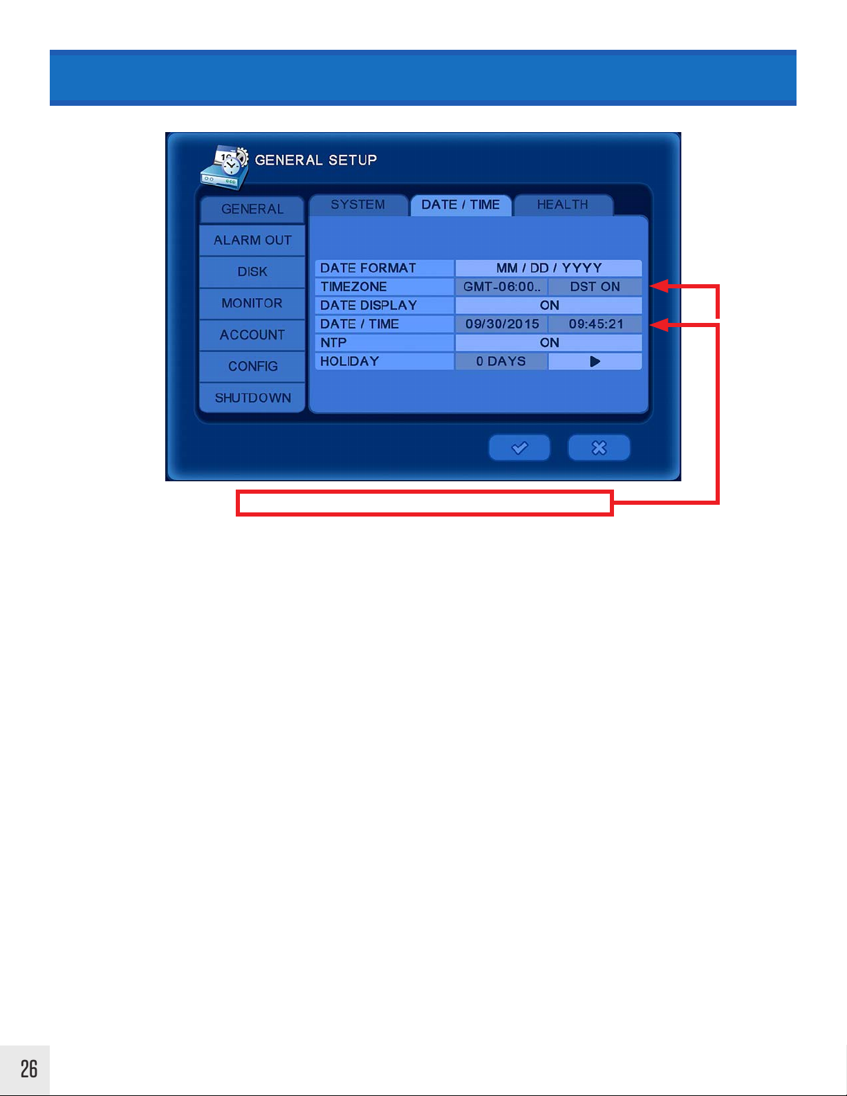
SETUP MENU > General > Date / Time
These areas are non-editable if NTP syncing is ON.
DATE FORMAT: Select the date format from the following: (YY/MM/DD) (MM/DD/YY) (DD/MM/YY)
TIME ZONE: Select the time zone and daylight savings time. DST will be automatically set to OFF if time zone which
does not use DST is selected.
DATE DISP L AY: Select ON for the date & time to be shown on the live view screen.
DATE / TIME: Change the date and time. Note: This information will be automatically synced when connected to the
internet. See NTP setting below.
NTP: Select the usage of the NTP (Network Time Protocol). With NTP the DVR is synchronized with NTP server and
will automatically obtain the correct time. The default server is [pool.ntp.org]. The user can input an alternate server
if desired.
Auto Sync: Synchronize automatically every day. Note: Before this option can be selected “Sync Now” must be
selected first.
Sync Now: Synchronize immediately.
HOLIDAY: Add or Delete a holiday. Holiday recording parameters can be chosen in the “Schedule Record” menu.
26
Page 29
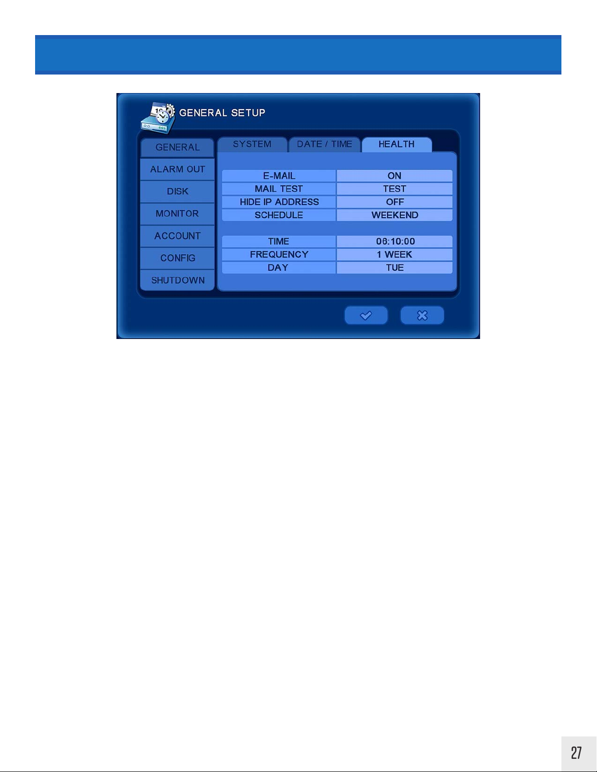
SETUP MENU > General > Health
Health check will preform a test of camera connections, and will email the selected recipients a list of errors, and
status of the device.
EMAIL: On / O
MAIL TEST: Sends a test email to the email address entered in the Network/E-Mail menu (from the Main Menu).
SCHEDULE: Day / Weekend / Month.
TIME: Time to preform check.
FREQUENCY: Select the frequency the health check will activate. 1-365 days / Day of the week / 1-31
27
Page 30

SETUP MENU > Alarm Out
ALARM OUT: Column shows alarm outputs listed 1-4.
SIGNAL+: Select On/O to enable or disable the corresponding alarm channel.
ALARM SET: Selecting SET will activate the connected alarm device for each output set to “ON”.
ALARM CLEAR: Selecting CLEAR will cancel the alarm for the activated device in the “Alarm Set Test”.
Alarm Inputs will vary depending on DVR model.
28
Page 31

SETUP MENU > Disk > Install
The install menu will display as a list of numbers which correspond to the type of device, the size of the device, and
the status for each device. Selecting a highlighted type will display the information on the drive which includes the
Vendor, Model number, Serial Number, and Status of the device.
INS TALL: Select to install a new device for the first time. This selection may be used to reformat an already installed
device. Doing so will erase all currently stored data on the device.
ERASE: Erases the data on a re-writable disk.
29
Page 32

SETUP MENU > Disk > Check / USB
EARLIEST RECORD: Shows the earliest recorded data information.
LATEST RECORD: Shows the most current recorded data information.
DISK CHECK: Check the data from the earliest recorded data to the latest. This checks for errors in the HDD. Clicking
START will open a progress window to show the percentage of the Disk Check completion. Once this process has
been started it must run until 100% completion.
NOTICE
USB RESET: Select SET to reset the USB connection. *This option is not available on newer model DVRs.
USB FORMAT: Select to format an inserted USB device. It is necessary for the USB device to be formated to FAT32
before backing up video to USB device. NOTE: Formating the USB will erase all data on the device.
Performing Disk Check can take up to 30 minutes or more
to complete depending on HDD size & how much recorded
video is on the HDD.
Once started the Disk Check can not be canceled.
30
Click the desired device. Make sure the USB
will be formated to FAT32 in the File System
options.
Page 33

SETUP MENU > Disk > RAID
This feature is only available on the Pro-Series, HD-SDI (HDVR16), & Hybrid (HY16) DVRs. Clinton DVRs that are
pre-built with RAID come set at RAID Level 1.
RAID: Displays RAID level.
RAID 0 - Splits data evenly between 2 HDDs. If one HDD fails, the data will be lost- there is no copy of the data.
RAID 0 build time is typically around 5 minutes.
RAID 1 - Mirrors/copies the same data to 2 HDDs. If one HDD fails, the second HDD will still have recorded data.
RAID 1 build time will range from 24-48 hours.
DISK: Displays disk status of installed HDDs.
STATU S: Displays RAID build status during setup and installed status after setup.
RATE: Display the progress during RAID setup.
NOTICE
• A minimum of 2 hard drives must be installed for RAID.
• The RAID HDD should be the same model and same size (i.e. 1 TB, 2 TB, etc..) as
primary Hard Drive.
• Reboot time is longer than normal boot time when initializing RAID. (About 5 minutes)
WARNING!
• When RAID is built, all previous HDD information will be deleted. Backup
needed data before starting RAID setup.
• Disk errors can occur if RAID HDD brand or model is dierent from primary
31
Page 34

SETUP MENU > Monitor
RESOLUTION: Select the resolution for the connected MAIN monitor. Selecting a higher resolution than the monitor
may be capable of can cause no image to be displayed and a SYNC OUT OF RANGE MESSAGE.
Selecting SWITCH or AUTO from the options will automatically select the best resolution for the monitor.
BORDER COLOR: Change the border color of the camera Multiplex views.
ALPHA BLENDING: Adjust the transparency of the DVR’s On Screen Display Menu.
• If a “SYNC OUT OF RANGE” message is displayed on the monitor, the selected resolution
is too high for the monitor.
• Press 1024768 then ENTER on the remote control to reset the monitor to 1024x768 resolution.
• Press 123123123 then ENTER on the remote to select the next lowest resolution.
32
Page 35

SETUP MENU > Account
Select the DVR tab to configure login settings at the DVR. Select the Client tab to configure login settings for
network access (SMS Software, Web Viewer or CEC Connect).
ADMIN: Administrators (up to 2 Admin) will have complete access to all DVR features.
USER: General users will have restricted access. They will not have access to DVR settings.
PERM: Give permission to USER accounts to allow access to Playback video, Backup video and PTZ control.
DEL: Delete the selected USER account. The ADMIN1 account can not be deleted.
When adding new user: input new ID and password. When deleting a user, confirm again to complete.
Default ADMIN1 password is 1111. Initial ADMIN1 user name & password
can be modified, but can not be deleted.
33
Page 36

SETUP MENU > Config
Setting up a configuration allows all the settings to be saved to the DVR. After the DVR setup has been completed,
the settings can be saved as a configuration. If something is changed in the future the original configuration can
be restored. Another DVR(s) can be quickly setup with the same settings by exporting the configuration to a CD
or USB drive, and then importing to another DVR.
SLOT: Label the slot to load or save configuration.
DATE: Displays the date the configuration was saved.
LOAD: Load the saved configuration.
SAVE: Save the current configuration.
DEL: Delete the configuration data on the Slot.
EXPORT: Export the current configuration to USB device or DVD.
IMPORT: Import the configuration data from USB device or DVD to the DVR. Camera, recording, system, and/or
network settings can be imported.
34
Page 37

SETUP MENU > Shutdown
RESTART: Restart the DVR. This is typically done to prepare the DVR for a firmware update.
SHUTDOWN: Shutdown the DVR. This is the recommended way to safely power o the DVR. Flipping the power
switch on the back of the DVR or disconnecting the power while the DVR is ON may result in damage to the hard
drive.
35
Page 38

CAMERA MENU > Camera
The CAMERA menu can be accessed by pressing MENU on the remote control or by right clicking with the
mouse, then selecting Main Menu.
Main Menu (Middle)
Setup Camera Event Record Network Info
36
CAMERA LABEL: Select the way in which the camera label is shown on the live screen. Each camera can show
the camera number [NUMBER], camera name [NAME], both of these by selecting [ALL], or to display none
of these by selecting [OFF].
NAME: Change the camera name. (The virtual keyboard will appear when a camera’s name is selected.)
INS TALL: Install or Uninstall a camera; when “Install+” is set to OFF the camera for the selected channel will
not be recorded or show on screen.
HIDDEN: Hide a selected channel on live view. When hidden the camera will not show on live view, but the
camera’s signal will continue to record as normal.
Page 39

CAMERA MENU > PTZ
PORT: Set the Baud Rate, Data Bit, Parity & Stop Bit parameters for the attached PTZ camera. Refer to the PTZ
camera’s manual for PORT settings and instructions on connecting to the RS-485 port.
ID: Select an ID number for the associated PTZ camera.
TYPE: Select the PTZ type from a list of common PTZ protocols.
For Clinton PTZ cameras:
4800 Baud Rate / 8 Data Bit / NO Parity / 1 Stop Bit
37
Page 40

CAMERA MENU > Spot
A Spot monitor will only show live camera footage. DVR menu functions will not be displayed on a Spot
monitor. Spot monitor options vary depending on the model of the DVR.
CAMERA: Select the camera(s) to be displayed on the Spot monitor. Select ALL to display every available
camera. Choose specific cameras to only display those cameras on the Spot monitor.
DEFAULT: Select the camera to display on spot monitor when sequence is o.
SEQUENCE: Select On/O to enable/disable camera sequencing on the spot monitor.
INTERVAL: Select the time interval before sequencing onto the next camera.
POPUP: Select ‘ON’ to enable pop-up full screen when an event occurs.
For DVR models (2015 Shadow Series) with BNC Main or Spot options:
BNC Output as SPOT MonitorBNC Output as MAIN Monitor
38
CAMERA: OFF CAMERA: ON (ALL or selected Camera(s)
Page 41

CAMERA MENU > Sequence
The MAIN monitor can sequence the individual full screen image or certain Multiplex views (Full Screen, Quad
Screen or 9 Cameras). The adjustments made in this menu can be turned ON or OFF by right clicking in the live
view and selecting Sequence.
PAGE DWELL TIME: Select the dwell time before the sequence proceeds to the next page on the main monitor.
Available on 1 / 4 / 9 camera screens. All cameras will be displayed.
CAMEO DWELL TIME: Select the dwell time before the sequence proceeds to the next channel while full screen.
Individual cameras can be selected ON or OFF during the Cameo Sequence.
CAMERA: Clicking Select+ will turn all cameras ON or OFF during the Cameo Sequence. Alternatively, individual
cameras can be selected ON or OFF during the Cameo Sequence.
Full Screen Only
1 / 4 / 9 Views
Right
Click
Full
Screen
Quad
Screen
4-Mini
3-Large
9
Cameras
39
Page 42

CAMERA MENU > Private Zone
ZONE ENABLE: Select from OFF or ON to enable or disable privacy masking. When OFF no privacy masks
will display. *Some DVRs oer: O, Live, or Live+Playback.
ZONE COLOR: Select the privacy zone color. (Blue, Black, White, Gray) *This option not oered on some
DVRs.
ZONE: Select the camera in which to apply the Privacy Zone. When a Zone is selected, the corresponding
camera image will appear on screen. From here you can set the Privacy Zone as follows:
1. Move the cursor to the desired privacy zone start point.
2. Click and hold the left mouse button on a square to set a starting corner. Move the cursor to the
desired opposite end corner and release the mouse button to define a block of cells.
3. Right-click with the mouse to bring up the Zone Menu. Using this menu, a selected area can be deleted
or saved, or you can return to the previous menu screen.
4. After clicking the check mark to confirm changes and returning to Live View; the area with the Privacy
Zone will now be blocked from view.
1 2
3 4
40
Page 43

EVENT MENU > Motion > Input
The EVENT menu can be accessed by pressing MENU on the remote control - or by right clicking with the mouse, then
selecting Main Menu.
Main Menu (Middle)
Setup Camera EVENT Record Network Info
MOTION>INPUT: Defines the parameters of the motion detection area(s).
ACTIVE+: Select ON to activate the motion detection area.
LEVEL+: Select the motion sensitivity level from low (1) to high (5).
AREA+: Define motion areas by selecting individual cells or groups of cells:
1. Left click with the mouse, or press
enter on the remote to select a cell.
2. Left click and drag the mouse cursor to
select multiple cells.
3. To select multiple cells with the remote,
press enter and use the arrow keys.
Press enter again to confirm.
4. When done setting up motion cells,
right click with the mouse, or press the
MENU button on the remote to
bring up selection options.
To enable motion recording, continuous recording should be turned OFF.
To apply settings to all cameras
in the column, click the tab at the
top of the column.
Only motion in this grid will be detected.Draw a motion area with the mouse.
41
Page 44

EVENT MENU > Motion > Action
MOTION>ACTION: Assign dierent actions for the DVR to perform when motion is detected.
RECORD: Enable a DVR channel to record when motion is sensed by a another camera. Select ON to activate the
motion area.
The default setting is to only record the channel in which motion has occurred.
Example: Camera channel 1 will only record when camera 1 senses motion.
The RECORD (Motion Event) can be setup to record dierent cameras other than the selected channel.
Example: When channel 1 senses motion, recording is triggered on channel 2 and 4.
Motion
Recording
ALARM: Select ON to enable an externally attached alarm. You can also apply a delay before the alarm is triggered,
and select the duration of the alarm (from 0-99 seconds).
42
BUZZER: Select ON to enable an audible chime from the DVR when motion occurs.
PRESET: Set the preset number. When motion occurs, a PTZ camera will move to the preset position. For information
on setting up PTZ presets see page 17.
E-MAIL: Enabling this function will send an E-mail to the selected recipients when a motion event occurs.
Page 45

EVENT MENU > Alarm In
Alarm In:
Input
ACTIVE: Select On/O to activate alarm.
NAME: Input the desired alarm name.
TYPE: Select the alarm type. ( NO : Normally Open, NC : Normally Closed )
Alarm In:
Action
RECORD: Set to On to record when the alarm input is triggered.
ALARM: Select On/O to enable or disable the selected alarm out.
BUZZER: Select On to enable an audible chime from the DVR when alarm input is triggered.
PRESET: Set the preset number. ( When alarm input is triggered, a PTZ camera will move to the preset position.)
EMAIL: Select On to receive an email notification when alarm input is triggered. Define email recipients in the
following menu: Setup / Network / Email.
43
Page 46

EVENT MENU > Video Loss
Video Loss:
Input
ACTIVE: Setting video loss to [ON] will trigger the items selected within the “Action” tab.
Video Loss:
Action
RECORD: Select which channels to record when video loss occurs.
ALARM: Select On to enable the selected alarm to trigger upon video loss of the associated channel.
BUZZER: Select On to enable an audible chime from the DVR when video loss occurs.
PRESET: Set the preset number. ( When video loss occurs, a PTZ camera will move to the preset position.)
44
EMAIL: Select On to receive an email notification when video loss occurs. Define email recipients in the following
menu: Setup / Network / Email.
Page 47

EVENT MENU > System Setup
System:
Warning
Click to change
from °Celsius (C)
to °Fahrenheit (F)
CHECK INTERVAL: Select the check interval time. This is how often the DVR will preform a smart check of the HDD.
DISK WARNING: POPUP and/or BUZZER when HDD temperature is checked and found to be out of the threshold.
THRESHOLD (HDD): Set the warning temperature threshold. Change from °Celsius to °Fahrenheit as needed.
CURRENT TEMP: Displays the current temperature of the HDD.
FAN SPEED WARNING: POPUP and/or BUZZER warning when fan speed falls below the threshold.
THRESHOLD (FAN): Set the warning fan speed threshold.
CURRENT TEMP: Displays the current fan speed (RPM).
System:
Disk
Automatically
disabled when HDD
overwrite is ON.
DISK FULL WARNING: Select to notify user when the HDD reaches the used space limit.
USED SPACE: Select the HDD full percentage.
ALARM: Select the channel for alarm output.
BUZZER: Select On to enable the DVR buzzer.
MESSAGE: Select On to enable a Pop-Up message; “DISK FULL” will be displayed on the screen.
45
Page 48

EVENT MENU > System Setup & Display
System:
Email
Set options to ON or OFF to receive an e-mail notification whenever any of following actions occur: POWER (On/
O), MENU (accessing DVR menu), LOGIN FAIL (failed attempt to login to DVR), DISK FULL (HDD is full), LOGIN
(login to DVR), or SMART (monitors internal operations of the HDD and warns of potential problems.
Email recipients can be setup in the following menu: Network / Email / Address.
Display
Setup
DIS P L AY: Set the duration of the full screen POPUP when an event occurs within the selected camera.
46
EVENT ICON: Select On to display the event icon at the bottom of the screen when an event occurs.
EVENT POPUP: When an event occurs the camera image will be displayed full screen.
Page 49

RECORD > Resolution
The RECORD menu can be accessed by pressing MENU on the remote control, or by right clicking with the mouse, then
selecting Main Menu.
Main Menu (Middle)
Setup Camera Event RECORD Network Info
Resolution options
will vary depending
on the type of DVR.
RESOLUTION: Set the recording resolution for each channel. This does not aect the live view of the camera.
Term Pixels (W x H)
CIF / STD 352 x 240
1
/2D1 / HIGH 720 x 240
D1 / HIGHEST 720 x 480
Q960H 480 x 240
960H 960 x 480
720p 1280 x 720
QHD 960 x 540
1080p 1920 x 1080
HD-SDI DVRS (CE-HDVR4 & CE-HDVR16)
To change the resolution on HD-SDI DVRs; go to CAMERA/
Camera/Resolution. The DVR will automatically restart when
changing the resolution.
NOTICE
• Once the Recorded Resolution is set, the recorded video quality can not be
increased. Ex: 960H (960x480) camera set to record at Half D1 (352x480) will
lower the quality of the video when recorded.
• Higher resolution video takes up more space on the HDD, but provides more
detail. The lower the resolution, the lower the video quality/detail.
47
Page 50

RECORD > Schedule > Typical
SETUP MODE: TYPICAL
Three basic recording schedules can be defined based on Day Time, Night Time & Weekend. The times & Weekend
days adjusted in this menu will use the settings from the RECORD menu.
DAY TIME - Set the recording start (FROM) & stop (TO) times for schedule recording. NIGHT TIME hours will
automatically be the hours remaining from the DAY TIME hours.
WEEKEND - Set the weekend days.
The FPS (Frames Per Second) & recording quality can be adjusted for each camera for both regular (Time)
recording and Event recording.
48
To only record EVENTS (Motion, Alarm, Video Loss) set the Time options to OFF.
Page 51

RECORD > Schedule > Custom
To select a block of
cells, first select a REC
button (1,2,3 or None)
then left click & drag the
cursor to the desired
block endpoint. To
select a single cell only,
left click on the cell.
Holiday dates can be
setup in SETUP MENU/
General Setup/Holiday.
SETUP MODE: CUSTOM
Three separate recording schedules can be defined based on a 24 hour day, days of the week, and holidays. The
recording groups (REC1,2,3) will use the settings from the RECORD menu.
REC 1 / REC 2 / REC 3 / NONE - Set the recording options for each hour of the day based on the settings for each
group. To adjust the settings for REC 1; click on the RECORD option on the sidebar, then click the REC 1 tab.
The FPS (Frames Per Second) and recording quality can be adjusted for each camera for both regular (Time)
recording and Event recording.
Selecting NONE will disable recording for the selected camera(s).
49
Page 52

RECORD > Event & Audio
Event:
These settings define the recording parameters before and after an event occurs.
PRE-RECORD: Set the record time before an event occurs. (The DVR will continuously store footage for the selected
“Pre-Record” time and then save that data when an event actually occurs.)
POST RECORD: Set the record time that you wish to record after an event occurs.
Audio:
50
RECORD: Select ON to enable audio recording for the corresponding channel. An audio device must be connected
to the back of the DVR.
Page 53
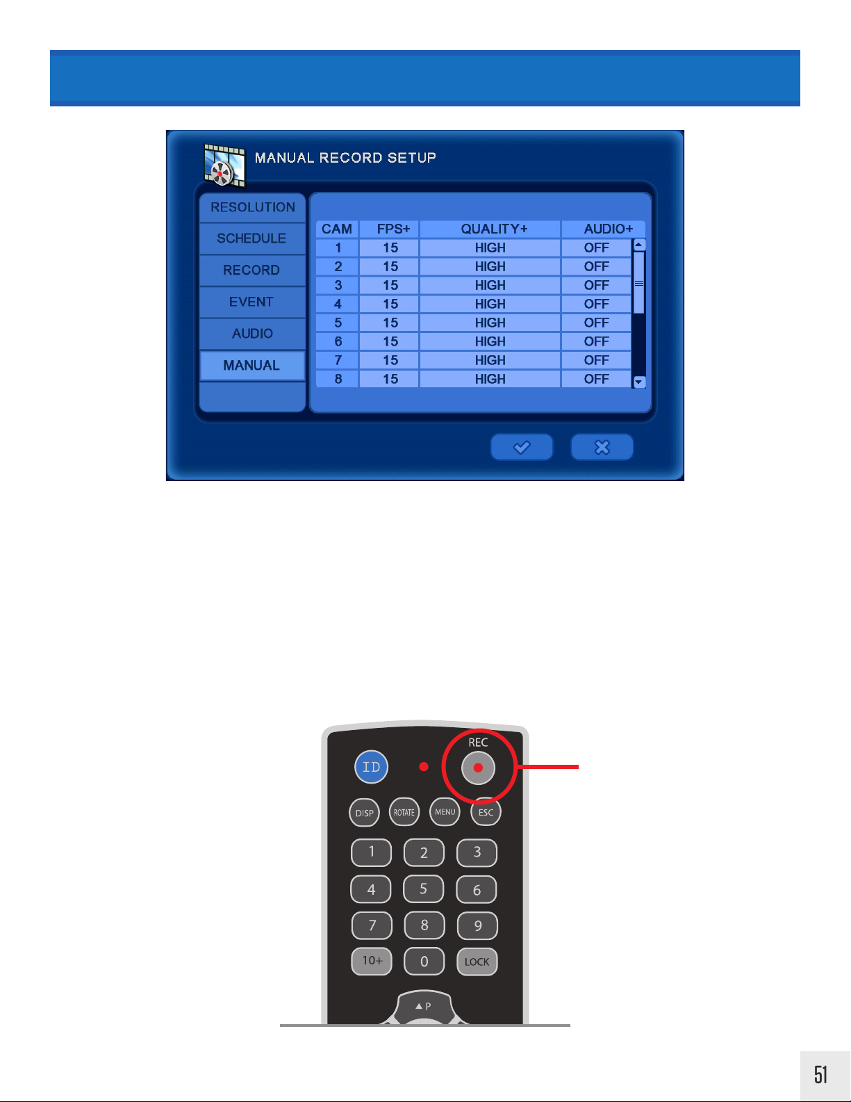
RECORD > Manual
MANUAL only applies to the remote control. Pressing the REC button on the remote control will begin Manual
recording & override any existing DVR recording settings. Press REC again to stop Manual recording.
FPS: Frames Per Second
QUALITY: Low / Normal / High / Highest
AUDIO: Select ON to enable audio recording for the corresponding channel. An audio device must be connected to
the back of the DVR.
Press REC to begin
Manual Recording
51
Page 54

NETWORK > Network Setup > Ethernet
The NETWORK menu can be accessed by pressing MENU on the remote control or by right clicking with the mouse,
then selecting Main Menu.
Main Menu (Middle)
Setup Camera Event Record NETWORK Info
DYNAMIC IP: Turn this setting ON to have the DVR automatically place network settings into the corresponding
fields. When ON the DVR IP Address, Subnet Mask, Gateway and DNS Server can not be edited.
1. Select ON to pull network settings.
2. Click the 3 button to save network settings.
3. After successful Check Internet test: turn Dynamic IP OFF, then click 3 to prevent the DVR from pulling an invalid
IP address in the future. *See Check Internet information in this section.
HOST NAME: Enter a desired host name. When/If email notifications are setup they will come from this name.
IP ADDRESS: Edit/Enter an IP address for the DVR.
SUBNET MASK: Edit/Enter the Subnet Mask.
GATE WAY: Edit/Enter the Gateway address.
DNS SERVER: Edit/Enter the DNS Server address.
CHECK INTERNET: Select START to initiate a internet connection test.
Successful Connection - “Internet access has succeeded”
Failed Connection - “Internet access has failed”
Dynamic IP must be OFF to edit
DNS Server address must be correct for successful check internet test.
52
Page 55

NETWORK > Network Setup > Client
Enter/Edit settings for remote access of the DVR using the SMS Software, Webviewer or CEC Connect phone App.
CLIENT ACCESS: Select “ALL” to enable access from all IP addresses. Select “RANGE” to limit access to only certain
IP addresses.
BEGIN ADDRESS / END ADDRESS: Enter the desired beginning and ending address for client access when RANGE
is selected above.
SMS PORT (TCP): Select the SMS port. (Default is 7000) SMS & CEC Connect use this port.
WEB PORT (TCP): Select the Web port. (Default is 80) Web Viewer uses this port.
REMOTE RESTART: Select ON to enable restarting of the DVR from a remote location via SMS Software.
REMOTE CONFIG: Select ON to enable configuration of the DVR from a remote location via SMS Software.
The IP Address from the
Ethernet tab and the
SMS Port number from
the Client tab are used
on the SMS software
and/or CEC app.
SMS Software DVR Info CEC Connect DVR Info
53
Page 56

NETWORK > Serial Setup
RS-485 INPUT SETUP: Match the settings from the PTZ keyboard if connected via RS-485.
SERIAL TYPE: Select an external device.
MODEL: Select the protocol to use. For Clinton keyboards select VIDO KB3N.
PORT: Select the Baud Rate / DATA bit / Parity / Stop Bit. For Clinton keyboards set to 4800-8N1.
Settings for Clinton Keyboard
Model VIDO KB3N
Baud Rate 4800
Data Bit 8
Parity NO
Stop Bit 1
54
Page 57

NETWORK > DDNS Setup
DDNS should only be set up if using a dynamic IP address. Check with the ISP (internet service provider) to see if
the network is using a dynamic IP address.
DDNS SERVER: Select a DDNS server; dyndns.com / changeip.com / ddnsdvr.com / ezddns.com / no-ip.com
HOST NAME: Enter the host name registered on the DDNS server.
USER NAME: Enter the user name registered on the DDNS server.
PASSWORD: Enter the password registered on the DDNS server.
ROUTER IP: Select On to send IP information to the DDNS server. This should be set to On when using a router.
STATU S: Check the connection status.
When using a DDNS server; first complete the host name, user name and password registration on the
DDNS server. Then enter the information into the DVR.
For information on setting up a free DDNS service, see the DDNS service setup guide included with the
DVR or download it online at www.clintonelectronics.com.
55
Page 58

NETWORK > E-Mail Setup > Address
SEND MAIL: Select ON to configure the email setup and to enable email sending.
SCHEDULE: Set to ON to define time frame to receive emails. ( From = Start time / To = End Time ). If set to
OFF, the DVR will send an email every time an action takes place- motion, DVR login/logout, disk full, video loss,
temperature warnings, etc.
E-MAIL ADDRESS: Enter the email address to receive notifications from the DVR.
Example E-Mail:
FROM: GTDvrmail@gmail.com
TO: yourname@emailaddress.com
DVR Action: Motion, Login, Video Loss, Health Check, etc.
SUBJECT: [GTDvr] Health Check Report
DVR Name : GTDvr
IP Address : 192.168.1.30
DVR Version : 1.01.01.32
Mac Address : 00:19:19:02:EA:25
HDD Usage : 1.97TB (99%)
Earliest Record : 10/07/2015 03:00:00
Latest Record : 10/18/2015 10:05:03
Abnormal Terminate : 0
SMART Alarm : 0
Video Loss : 213
H/W Error : 0
HDD I/O Error : 0
Camera No. : 4
Record Information :
Camera1 : Time Record
Camera2 : Time Record, Motion Record
Camera3 : Time Record
Camera4 : Time Record
56
Page 59

NETWORK > E-Mail Setup > Server
MAIL SERVER: Select the mail server; SMTP server or DVR System.
SMTP SERVER: This is the most common selection. Most common/popular email servers such as Gmail, Outlook,
Yahoo, etc have SMTP email servers.
DVR SERVER: This should only be selected if the DVR is part of a local network that has it’s own email server.
E-MAIL: Input the user email address. This will be the “FROM” email address when the DVR sends an email. Some
email account logins are case-sensitive so enter the information exactly as one would to login in.
SMTP SERVER: Input the SMTP server address; smtp.gmail.com, smtp.live.com, smtp.mail.yahoo.com, etc.
SMTP PORT: Input the SMTP server port number.
MAIL TEST: Sends a test email to the address entered on this menu.
NOTICE
• If no Mail Server information is entered emails will not be sent.
• If the email login/password contains uppercase & lowercase characters enter it exactly
as you would from a computer.
• Avoid e-mail addresses & passwords with special characters ( & : / # * + ). These special
characters can sometimes cause the e-mails to not send.
• Selecting DVR Server disables editing information in this menu.
• If the password for the email address is changed (from email account settings), it must
be updated on the DVR for emails to be sent.
57
Page 60

NETWORK > Net Frame
Net Frame defines the network limits for Frames per Second and quality for the live viewer. Setting to a lower
quality and frames per second will result in less data transfer for lower bandwidth applications. These settings
do not aect live view or recorded video on the DVR.
FPS: Select the desired frames per second for live viewer.
QUALITY: Select the desired quality level for live viewer.
58
This feature is disabled/not available to edit on some models.
Page 61

INFO
The INFO menu can be accessed by pressing MENU on the remote control then selecting the INFO icon, or by pressing
the UP arrow on the remote.
With the mouse the INFO menu can be accessed by moving the mouse cursor to the top of the screen or by rightclicking, then selecting Main Menu, then clicking on the INFO icon.
Top Menu
SettingsSearch INFO Log-OutBackup
Main Menu (Middle)
Setup Camera Event Record Network INFO
Press UP to display
menu screen
59
Page 62

INFO > System Log
SYSTEM LOG: A numbered list of DVR events with the time & date of the event can be found here. Events such as
Login/Logout, Video Loss, Power On/O, Firmware Updates, Remote Login Info, etc.
Click the Left or Right arrow buttons or use the scroll wheel on the mouse to move through the list of events.
EXPORT: The System Log can be exported to a disk or USB device for review on a computer. (file saved as .TXT)
1. Insert a disk (CD-RW or DVD-RW) or connect a USB device to the DVR.
2. Click the EXPORT button.
3. [TARGET] Select the location where the list will be saved: USB device or disk.
4. [FOLDER] Give the folder a name if desired.
5. Click the 3 button to export the system log.
60
USB should be formated to FAT32. To format, refer to: SETUP MENU > Disk > Check / USB
Page 63

INFO > Status
STATUS displays important information about the HDD, recorded video settings and audio settings. These settings are not editable in this menu.
DISK: Shows DVR information at a glance.
EARLIEST RECORD: Oldest recorded video.
LATEST RECORD: Most recent recorded video.
DISK CAPACITY: Total storage capacity of installed HDD(s).
USED SPACE: How much space on the HDD has recorded video.
AVAILABLE SPACE: How much space is left of the HDD.
HDD OVERWRITE: Shows if the HDD will overwrite oldest video once the HDD is full. To change HDD Overwrite
settings: SETUP MENU > General > System > HDD Overwrite
HDD INFORMATION: Display information on specific installed HDD(s).
RECORD: Shows the current scheduled recorded video resolution and video quality settings (FPS, Quality).
AUDIO: Shows audio recording settings.
CAMERA: Shows input resolution from connected cameras. (Hybrid models only)
61
Page 64

INFO > Version
DVR PROGRAM: Displays the currently installed version of Firmware on the DVR. It is recommended to regularly
check for firmware updates oered on our website: www.ClintonElectronics.com
PRODUCT DATE: Displays the build date of the DVR.
VIDEO: Displays the resolution and total FPS (frames per second).
AUDIO: Displays the number of available audio inputs.
VIDEO FORMAT: NTSC or PAL.
MAC ADDRESS: Displays the MAC address of the DVR.
62
It is recommended to regularly check for firmware updates oered on our website: clintonelectronics.com
Page 65

SEARCH
To review recorded video, move the mouse cursor to the top of the screen and click the SEARCH icon, the first icon from
the left; or with the remote control press the UP arrow to display the top menu. Alternatively- press the Search button
on the remote to display the SEARCH menu.
Top Menu
SettingsSEARCH Info Log-OutBackup
There are several dierent methods of searching recorded video: Playback, Quick Search, Calendar search, Event
Search, Overlapped List, Museum Search, Go To First & Go To Last.
PL AYBACK : Replays the latest recorded video from the selected
channel.
QUICK SEARCH: Enter the exact time & date information to search.
CALENDAR: Displays a calendar with colored bars to indicate recording
type to help narrow search selection.
EVENT SEARCH: Enter the date of the event and filter by event type;
motion, alarm in, video loss.
OVERLAPPED LIST: Search for data that occurs from manually
changing the time backwards or when an hour is lost from daylight
savings time.
Video can also be searched from a CD/DVD or USB device that has backed-up
video by clicking in the TARGET row and selecting to appropriate drive.
MUSEUM SEARCH: Search an exact area of a selected camera by
drawing a motion box.
GO TO FIRST: Quickly jumps to the earliest/oldest recorded video on
the DVR.
GO TO LAST: Quickly jumps to the latest/most recent recorded video
on the DVR.
GO TO JUMP: Only selectable when actively searching video. Quickly
change the playback time by as much as 12 hours.
63
Page 66

SEARCH SCREEN LAYOUT
2
1
3
10
9
4
8
5
6 7
1. Execution Information Message
2. Camera Name
3. Search Status Icons
4. Repeat Segment: S-Start Time, E-End Time
5. Backup Progress Status %
Search Status Icons:
Record Icon: Shows when recording is active.
Time Icon: Shows when time (schedule) record mode is active.
Motion Icon: Shows when motion occurs.
Sensor Icon: Shows when the external sensor is triggered.
6. Audio Icon - displayed when audio is present
7. Date and Time of Recorded Video
8. Zoom 2x / 4x Location
9. Video Area
10. Search/Playback Speed
Playback Speed Icons:
Play
Pause Play 1
2x
Fast
Forward
Frame
3x
Fast
Forward
Play
Half
Speed
4x
Fast
Forward
Play
Quarter
Speed
5x
Fast
Forward
Play
Eighth
Speed
64
Page 67

SEARCH MENU ICONS EXPLAINED
While performing a search, move the mouse cursor to the bottom of the screen to display the Search control panels.
Control panel functions can alternatively be selected by pressing the corresponding buttons on the remote control.
To toggle between the two control panels click on either the Left or Right arrows on opposite sides of the control
panels.
1
1. Fast Reverse
2. Reverse Play
3. Pause
4. Play
5. Fast Forward
6. Repeat Segment
1st Mouse Click: Segment Start
2nd Mouse Click: Segment End
3rd Mouse Click: Cancel Segment
2
3
4
5
6
7
7. Change Multiplex View
8. Cycle Channels in Multiplex View
9. Preview Mode
10. Museum Search Mode
11. Main Menu (Middle Menu)
12. Exit Search
8
9
10
11
12
1
1. Jump backward 1 hour
2. Jump backward 30 minutes
3. Jump backward 10 minutes
4. Jump backward 5 minutes
5. Jump backward 1 minute
6. Jump forward 1 minute
2
3
4
5
6
7
7. Jump forward 5 minutes
8. Jump forward 10 minutes
9. Jump forward 30 minutes
10. Jump forward 1 hour
11. Main Menu (Middle Menu)
12. Exit Search
8
9
10
11
12
65
Page 68

Playback:
SEARCH > Playback & Quick Search
To access PLAYBACK: in the LIVE View- right click on a desired camera, then
select playback.
PLAYBACK replays the latest recorded video from the selected channel. The
recording icon will change from RED to BLUE.
The selected channel will Playback recorded video while the remaining
cameras display LIVE video. Use the search controls as necessary to search
forwards or backwards through video.
BLUE icon indicates
Playback Mode
Remaining cameras
display LIVE video
The following Search Menu items can be accessed by moving the mouse cursor to the top of the screen and clicking
the SEARCH icon, the first icon from the left, or with the remote control press the UP arrow to display the top menu.
Alternatively- you can press the Search button on the remote to display the SEARCH menu.
Quick Search:
Quickly search through recorded footage from all channels by entering
the exact Year / Month / Day / Hour / Minute.
66
Page 69

SEARCH > Calendar
Displays a calendar with colored bars to indicate recording type to help
narrow search selection.
1. Select a highlighted day. Days not highlighted have NO recorded
video.
2. Drag the arrow indicator to the desired hour.
3. Click the 3 mark to start reviewing video from that hour or click in
the timeline area to narrow the selection down to minutes.
Date & Time information is displayed at the bottom of the timeline. Use
the scroll bar to scroll up or down to view more channels.
1
Click on highlighted DAY
3
2
Drag arrow to select HOUR
Color Bar Description
BLUE Time Recording
Drag arrow to select MINUTE
RED Event/Motion Recording
TEAL Audio Recording
67
Page 70

SEARCH > Event Search
DATE: Enter the Year / Month / Day to search for events.
MOTION: Filter video for Motion.
ALARM IN: Filter video for Alarm Input from an external source.
VIDEO LOSS: Filter video for Video Loss.
SELECT CAMERA: Search ALL cameras, or select specific cameras to
view.
VIEW SEARCH LOG: Displays all selected filters for event search.
Events are detailed with time/date, camera number and event type.
Events (Motion, Alarm In, Video Loss) must be setup and
enabled for the Event Search to function. If the events are
not ON, no search results will be found.
Enter date information
Select camera(s) to search
EVENT SEARCH RESULT: Use the scroll wheel on the
mouse to scroll up or down through the list. If the list
is blank - no events were found.
NO: Select the event segment you wish to playback.
PREV: Display previous search results page.
NEXT: Display next search results page.
GOTO: Input an event page start number.
68
Page 71

SEARCH > Overlapped List
OVERLAPPED LIST: Search for overlapped data that occurs from
removing DST (daylight savings time) or from changing the time
backwards on the DVR.
NO: Click on the desired number to view the video from the overlap list.
QUICK SEARCH: Search for video using the Calendar search option.
EVENT SEARCH: Search for video using Event triggers.
When time is changed, the
recorded video from that time will
not display in regular searches.
This hour of “lost” recorded video
is saved in the Overlap List.
DEL: Deletes the selected overlapped video(s).
69
Page 72

SEARCH > Museum Search
Museum Search is a very eective way to search for motion in only a specific region of an individual camera. Example;
a camera placed next to a road will have motion events constantly making searching dicult. Using the search grid in
museum search narrows down the motion to a specific area to search. Museum Search will search for/detect motion
that has occurred - even if Motion Recording is not enabled.
START TIME: Enter the Date & Time info to start the search from.
END TIME: Enter the Date & Time info to stop the search.
CAMERA: Select the desired camera to search for motion.
AREA: Select a motion search area-
1. Press SET.
2. Move the mouse cursor to the desired start point.
3. Click & hold the left mouse button on a square to set the corner.
4. While holding the mouse button down, drag the highlighted box to the desired size.
5. Clicking o/releasing the mouse button sets the search grid.
SEARCH: Search the selected Area for motion. Depending on the Start & End Times this could take several minutes to
complete.
CLOSE: Exits from the Museum Search menu.
70
Draw a motion area to search. Only motion in this grid will be searched.
Page 73

SEARCH > Museum Search
Museum Search continued...
The Museum Search results will only display motion that took place in the previously defined search area.
*Red boxes shown to indicate where the search area was. They do not display on the DVR.
SEARCH RESULTS:
Move the mouse cursor to the bottom of the screen to display the Museum Search control panel.
1 2 3 4 5
1. Page Left through search results
2. Page Right through search results
3. View Search results in list form
The time to complete the Museum Search will vary depending on the Start & End Times. The longer the time
frame to search, the longer the search will take to complete.
4. Display Museum Search settings. Clicking the STOP button will stop
the search if it is taking too long.
5. Exit the Museum Search results preview.
Museum Search can be quickly accessed from any search method by clicking on the Museum Search
icon (running man icon) from the Search control panel at the bottom of the screen.
71
Page 74

SEARCH > Go To First / Go To Last
GO TO FIRST: Quickly jumps to the earliest/oldest recorded video on
the DVR.
GO TO LAST: Quickly jumps to the latest/most recent recorded video
on the DVR.
GO TO JUMP: Only selectable when actively searching video. Quickly
change the playback time by as much as 12 hours. To access move the
mouse cursor to the top of the screen and click on the Search icon for
a second time. GO TO JUMP will now be displayed at the bottom of the
menu.
GO TO JUMP menu. Quickly jump forwards or backwards up to 12 hours.
72
Page 75

SEARCH > Panorama & Preview
To access Panorama & Preview search options, you must be viewing
a single channel. Right click on the video area to bring up the CAMEO
MENU for that channel.
PANORAMA: Display up to 16 consecutive still frames of a selected
channel during playback. Each window of the selected multiplex view
(4 / 9 / 16) represents 1 frame of video. The higher the recorded frame
rate (FPS) the faster the still frames will refresh.
PREVIEW: Displays video from the selected channel as a still image
from every 4 minutes of video.
PANORAMA
Displays video frame
by frame in a multiplex view (4/9/16).
PREVIEW
Each frame is a still
image taken every 4
minutes.
PREVIEW can be quickly accessed from any search method by clicking on the Preview icon (checkerboard icon) from the Search control panel at the bottom of the screen, or right clicking, then
selecting PREVIEW.
73
Page 76

BACKUP
Top Menu
SettingsSearch Info Log-OutBACKUP
A blank CD-R, DVD-R, or a formatted USB drive is required for video backup. (USB drives
up to 32GB and must be formatted to FAT32) For formatting information refer to: SETUP
MENU > Disk > Check/USB > USB Format.
74
Press BACKUP to
display menu screen
Page 77

BACKUP
Available space on
selected device.
Click ESTIMATE before
writing save file.
TO BACKUP RECORDED VIDEO:
1. Insert CD/DVD (if the DVR is equipped with a CD-RW/DVD-RW disk drive) or formatted USB into the DVR.
2. Move the mouse cursor to the top of the screen and click the BACKUP icon, the second icon from the left. Or with
the remote control press the Backup button to display the BACKUP menu.
3. Click [NONE] in the Target row. If a USB or CD/DVD is inserted into the DVR it will be displayed.
4. Select which device to use.
5. Set From (start) & To (stop) Dates & Time. The longer the time frame, the longer it will take to backup video.
6. Name the file if desired by clicking [backup] in the BACKUP TITLE row.
7. Click the [ON] button next to SELECT CAMERA to select which cameras will be saved. The more cameras selected-
the larger the file size.
8. Click the [ESTIMATE] button. Doing so ensures there is enough room on the selected disk/USB for the saved video.
If the file is too large it can not be saved. To lower the file size either shorten the amount of time to be saved or select
fewer cameras.
9. Click [WRITE] to start the backup process. A progress bar displays the percentage of completion.
10. Once the video is backed up, the DVR will beep. It is now safe to remove the USB device or disc from the DVR.
Select the desired drive/device
Click STOP to
cancel the backup
Click HIDE to return to
regular DVR operation
75
Page 78

BACKUP > View Saved Video
The backed up video is saved as a proprietary file type and can not be viewed without the embedded DVR
player software. (The DVR player software is saved to the device at the same time the video is being saved).
Open DVR Player
Folders containing
USB device with
saved video
saved video
TO VIEW SAVED VIDEO FROM BACKUP:
1. Insert CD/DVD or USB with saved video into a Windows PC. Currently not supported for use on MAC computers.
2. Locate the device with saved video.
3. Open the DVR Player software.
4. Locate the device with saved video from the menu bar on the right.
5. Open the folder containing the saved video.
6. Drag & Drop the desired clips into the multiplex view on the left.
7. Click the PLAY button to play video. Video always loads in PAUSE mode.
DRAG CLIPS HERE
76
Folder with desired saved video Press PLAY after clips are loaded
Page 79

REMOTE ACCESS > Web Viewer > Internet Explorer
Clinton Shadow, Pro, HD & Hybrid Series DVRs can be accessed on a local network or remotely with Internet Explorer,
Firefox or Safari. Functionality is varied depending on the type of browser.
DVR network settings must be properly set up for the Web Viewer to function. To access the DVR via the internet,
port forwarding must be configured in the router according to the WEB and SMS port settings in the DVR. The default port settings are 80 for WEB and 7000 for SMS.
Internet Explorer Safari & Firefox
WEB VIEWER ON INTERNET EXPLORER:
1
Open Internet Explorer.
Go to: Tools > Internet Options > Security >
2 3
Custom Level
Scroll down to Download Unsigned ActiveX
Controls.
Select Prompt, then click OK to save settings.
77
Page 80

REMOTE ACCESS > Web Viewer > Internet Explorer
4
Enter the IP Address of the DVR followed by the WEB port number in the address area of the browser. (this can be
found in: NETWORK > Network Settings > Ethernet/Client)
5
Click Install when prompted for ActiveX control.
Login in using the Client ID & Password. To edit
6 7
login information: SETTINGS > Account > Client.
Default login ID is remote & password is 1111.
Then click the Connect button.
“Success to login” will display briefly if the login
information was correct.
After successful connection the video from the
DVR will load into the multiplex window.
78
NOTICE
• Web Viewer does not work on the Google Chrome or Microsoft Edge browser.
• Call Clinton Tech Support for help with router port forwarding.
Page 81

REMOTE ACCESS > Web Viewer > Internet Explorer
Click on an image to select that camera to make adjustments. Double click the selected image to fill the player window.
An image outlined in BLUE
indicates that it is selected.
1
2
3
4
5
6
1. DDNS Settings
2. Current Date & Time Info
3. Multiplex Views
4. Select All Cameras
Image Adjustment PTZ Adjustment
Alarm SEARCH
Frame Rate
Brightness
Contrast
Filter
Alarm Out
On/O
5. Full Screen
6. Control Options
7. Connect
8. Disconnect
7 8
Move PTZ
Zoom IN
Zoom OUT
Open Search
Exit Search
• The adjustments made to the camera image (Brightness/Contrast) only apply to the Web Viewer image. They do
not change the image brightness/contrast on the DVR.
• The Frame Rate can not play higher than what the Net Frame is set to on the DVR. (NETWORK > Net Frame)
79
Page 82

REMOTE ACCESS > Web Viewer > Internet Explorer
SEARCH: Click the Open button to display the Record Search
window. This window is similar to CALENDAR SEARCH on the DVR.
1. Click on the calendar date to search video.
2. Move the slider on the bottom of the timeline to the desired
time.
3. Click the Load button to playback selected video.
4. Click Exit when done to return to Live View.
Right Click in the player window to display additional options.
View Single: Display the selected camera full screen in the player window.
Zoom In: Zoom in (digital zoom) on selected video. When zoomed in- click and drag around in the window to view more
of the image. Right click again to zoom in further or to zoom out.
Live Audio: Listen to audio from the selected camera. Audio must be set up and connected to the DVR to function.
OSD Setup: Turn On/O the On Screen Display information; Camera Name, Date, Time, Event & Channel Number. Click
OSD Color to change the color of the OSD text.
Use DirectX: Leave this checked.
Freeze: Pauses the selected live video.
Sequencing: Cycle through live attached camera channels. Note: All screens except the 16 Camera screen will sequence
any channel selected with cameras not shown on screen if more cameras are connected than are shown on the screen.
Print & Save: Takes a snapshot of the video and saves it as a .BMP or oers the option to print the image.
80
Page 83

REMOTE ACCESS > CEC Connect App
Clinton Shadow, Pro, HD & Hybrid Series DVRs can be
accessed from an iOS or Android device using the CEC
Connect App.
DVR network settings must be properly setup for the CEC
Connect App to function. To access the DVR via the app;
port forwarding must be configured in the router according to the SMS port settings in the DVR. The default port
settings are 7000 for SMS.
Screen images from iOS ver9.1
1
Open the App Store or Google Play Store. Search
for CEC Connect or Clinton Electronics.
3
Open the app after installation.
CEC Connect
3
Install the CEC Connect app.
Compatible with iPhone, iPod touch,
and iPad. Requires iOS 5.1.1 or later.
View more info on the iTunes App Store.
Compatible with most Android devices.
Requires Android 2.1 or later. View
more info on Google Play.
4
Click the + icon to add a new DVR.
Multiple DVRs can be saved and quickly accessed,
edited and deleted from this main menu.
5
Enter the IP Address from the Ethernet tab and the
SMS Port number from the Client tab (NETWORK >
Network Setup > Ethernet > Client). The Name option
can be dierent from the DVR Host Name.
GTDvr
192.168.1.30
7000
If using a Host Name (DDNS), enter
that info in place of the IP Address.
81
Page 84

REMOTE ACCESS > CEC Connect App
6
Enter the Client login information. Default User is remote and password 1111.
remote
1111
7
After the IP Address, Port Number & Login information has been entered, press Save.
GTDvr
192.168.1.30
7000
remote
••••
8
DVR names & addresses are stored here. Press the
desired DVR to display live video.
GTDvr
192.168.1.30:7000
HD-SDI
173.15.127.114:7734
HYBRID
173.15.127.114:6734
Press the i to display and edit the DVR
information.
9
To delete a DVR listing, press EDIT, press the red circle next to the DVR to delete.
GTDvr
192.168.1.30:7000
HD-SDI
173.15.127.114:7734
HYBRID
173.15.127.114:6734
GTDvr
192.168.1.30:7000
HD-SDI
173.15.127.114:7734
HYBRID
173.15.127.114:6734
The DVR will slide over to reveal a DELETE button.
Press to confirm DELETE.
82
Screen images from iOS ver9.1
Page 85

REMOTE ACCESS > CEC Connect App
10
To change the order of the DVR listing; press EDIT, then press and hold the 3 horizontal lines and move to the
desired location
GTDvr
192.168.1.30:7000
HD-SDI
173.15.127.114:7734
HYBRID
173.15.127.114:6734
HYBRID
173.15.127.114:6734
HD-SDI
173.15.127.114:7734
GTDvr
192.168.1.30:7000
LIVE VIEW MENU SCREEN:
CEC Connect can be viewed either in Portrait (vertical) or Landscape (horizontal) mode. Rotate the phone to change
between the two viewing options.
1 2 3
TOP
MENU BAR
1. Exit to Main Menu (DVR Address Menu)
2. DVR Name
3. Search Recorded Video
4. PNG (Image) Export
5. Freeze Live Video
Frame Rate
(hidden under menu bar)
BOTTOM
MENU BAR
987654
6. Date & Time Info
7. Multiplex Views (1 / 4 / 9 / 16)
8. PTZ Control
9. Help
Screen images from iOS ver9.1
83
Page 86

REMOTE ACCESS > CEC Connect App
HIDE MENU BARS:
Tap ONCE on the screen to hide the menu bars. Tap ONCE again to display the menu bars.
CHANGE MULTIPLEX VIEW:
Tap the MULTIPLEX icon to change how many cameras are displayed on the screen.
Default is
16 Camera View
9 Camera View 4 Camera View Single Camera View
CHANGE CAMERA DISPLAYED:
Swipe LEFT /RIGHT / UP / DOWN to cycle through dierent camera views. *Does not change when viewing 16 cameras.
Double Tap a camera
to view full screen.
84
Swipe SwipeSwipe
Screen images from iOS ver9.1
Page 87

REMOTE ACCESS > CEC Connect App
SEARCH RECORDED VIDEO:
Tap the SEARCH button to view recorded video. Enter the desired date & time to search recorded video. Once in
SEARCH mode Multiplex camera views and full screen viewing function the same as in Live View.
1 2 3 4
5
1. Exit to Main Menu (DVR Address Menu)
2. Hi-speed Scrubbing
3. Search Date & Time Menu
4. Return to Live View
5. Date & Time Info
6. PNG (Image) Export
7. Jump Backward 15 Seconds
8. Fast Rewind (up to 32x)
15
76
9. Rewind
10. Pause
11. Play
12. Fast Forward (up to 32x)
13. Jump Forward 15 Seconds
14. Change Multiplex View
15. Search Speed
1312111098
14
Screen images from iOS ver9.1
85
Page 88

REMOTE ACCESS > CEC Connect App
PTZ CAMERA CONTROL:
After selecting a PTZ camera; tap the PTZ icon to make adjustments to the camera’s position and zoom.
Preset Position
Focus Near / Far
Zoom In / Out
PTZ Joystick
The PTZ camera must be correctly setup on DVR to function.
Depending on network connection speed, adjustments may take a second to display .
IMAGE EXPORT:
To export an image of a selected camera, tap the PNG Export icon. This image can be found in the Photo Album.
86
CEC Connect must have access to the Photo Album
for images to save. To turn On/O, go to iOS Settings,
then scroll down to find CEC Connect.
Screen images from iOS ver9.1
Page 89

PORT FORWARDING BASICS
• Router IP addresses and configuration pages vary by manufacturer. Use the following information as a basic
guide in configuring a router to set up port forwarding.
• Refer to the Port Forwarding section of the user manual for the router or visit www.portforward.com and click on
the Port Forwarding Guides link for more detailed information.
• Call Clinton Tech Support for help with router port forwarding.
1. Open an internet browser (Internet Explorer, Google Chrome, Safari, etc.)
2. Log in to the router. This will usually be the Default Gateway found in NETWORK > Network Setup > Ethernet >
Gateway.
3. Enter the login information for the router.
4. After successful login to the router find the Advanced Settings or Firewall Settings.
5. Find the Port Forwarding/Port Triggering section and select Port Forwarding.
6. Service Types: TCP/UDP should be enabled.
7. Enter the Web Port number from the DVR (default is 80) into the Starting Port and Ending Port.
8. Enter the IP address of the DVR (found in NETWORK > Network Setup > Ethernet > IP Address).
9. Click OK or SAVE.
These steps will need to be repeated to open the SMS Port (default 7000). Instead of entering 80 for the Starting and
Ending Ports, you will enter 7000.
87
Page 90

DDNS Setup
DDNS (Dynamic Domain Name System) is a system that monitors changes in the user’s IP Address. Most small
business or residential users have a dynamic IP address that can change periodically. When the IP address changes
any devices that were using that older IP address will be unable to connect to the DVR. When DDNS is setup,
the DVR will detect changes in the IP address and send that new info to the DDNS service. The DDNS service
will update the IP address (numbers) but the Host Name will remain unchanged, allowing uninterrupted remote
connection to the DVR.
OLD IP Address
DDNS
DVR detects changed IP
Address & sends NEW
info to DDNS Service
ISP
192.168.1.2
192.168.8.7 192.168.8.7
ISP changes the users
Public IP Address
(dynamic IP Address)
192.168.1.2
DDNS Host Name
DDNS Service changes the
GTDvr01.cedyn.com
www
1
After logging onto the DVR using Internet Explorer, click on the DDNS Settings icon located next to the Web View-
GTDvr01.cedyn.com
er version number in the upper right hand corner of the Web Viewer screen.
IP Address associated
with the Host Name
192.168.8.7
88
2
Change DDNS Select to: http://www.no-ip.com,
then click Create Account.
DDNS Setup
DDNS Information
DDNS Select :
DDNS User Name :
DDNS Password :
DDNS Host Name :
no-ip.com
Create Account
Router-IP Mode
Home
3
Create a User Name & Password, followed by contact information. Click the check box to agree to
the TOS. (Terms Of Service available at http://www.
no-ip.com)
No-IP Setting : Create Account
Account Information
User Name :
Password :
Confirm Password :
ClearApply
GTDvr01
Minimum of 4 characters in length.
******
Minimum of 6 characters in length.
******
Check
You agree to the TOS
Email :
First Name :
Last Name :
Postal Code :
John
Smith
61111
Next
Click Next to proceed.Click to check availability
of chosen User Name.
Page 91

DDNS Setup
4
Create a desired Host Name. Select cedyn.com from the Dropdown Menu (this is the free service oered by Clinton Electronics, other options may involve mothly fees). Enter the public IP Address that the DVR is connected to.
This is dierent than the IP Address of the DVR. If you are unsure of the public IP, visit: http://whatsmyip.org
No-IP Setting : Add Host
Host Information
Host Name :
IP Address :
5
Verify that all the information on this window is
GTDvr01
173 . 15 . 127 . 113
cedyn.com
correct and click Ok to confirm.
No-IP Setting : Finish
Account Information Account Information
User Name :
First Name :
Last Name :
Postal Code :
GTDvr01
E-Mail :
yourname@emailaddress.com
John
Smith
61111
Host Name :
IP Address :
GTDvr01.cedyn.com
173.15.127.113
Next
6
The DDNS account info will be displayed automatically. Click the check for Router-IP Mode. Click
Apply.
DDNS Setup
DDNS Information
DDNS Select :
DDNS User Name :
DDNS Password :
DDNS Host Name :
no-ip.com
GTDvr01
******
GTDvr01.cedyn.com
Router-IP Mode
Home
Create Account
Ok
ClearApply
This DDNS info will be pushed to the DVR after Apply is
clicked.
• If the DVR is connected to a router, the Web and SMS ports used in the DVR must be forwarded in the router to
the DVR’s IP address using TCP and UDP protocol.
• If the web port has been changed from the default of 80, it must be entered after the DDNS Host Name with a
colon : and then the port number. Example: http://GTDvr01.cedyn.com:81
89
Page 92

FIRMWARE UPDATE
Latest DVR firmware can be found online at www.ClintonElectronics.com/support.html.
Follow the procedure below to install the firmware onto your DVR.
1. Insert a USB device (Formated to FAT32) into a computer.
2. Download the appropriate DVR firmware from www.ClintonElectronics.com/support.html
3. Save the firmware update to the USB. Do Not open the contents of the firmware update or rename the file.
Opening, modifying or renaming the firmware update will make it unreadable by the DVR.
4. Remove the USB device from the computer.
5. Insert the USB device into the DVR.
6. Restart the DVR. To restart: SETUP MENU > Shutdown > Restart
7. Confirm the firmware update during the DVR restart. Once the update starts do not remove the USB device
from the DVR. The firmware update can take several minutes to complete depending on the size of the update.
8. After successfully updating the firmware; remove the USB device when prompted then click the 3 mark.
9. The DVR will perform a self-restart. This can take several minutes.
10. After this second restart an “Upgrade Completed” window will be displayed. Click the 3 mark to return to
regular DVR functions.
Download & Save firmware update from
ClintonElectronics.com/support.html onto USB
Confirm the firmware update by clicking the
not remove USB from DVR or power down
NOTICE
• Do Not remove the USB device from the DVR until the firmware has
successfully been installed.
• If the USB device is not removed after prompted, the DVR will initiate the
firmware update again after restart.
3 button, do
Insert USB with firmware update into DVR & Restart
Remove USB from DVR when prompted
90
Page 93

Page 94

DVR User Manual
Shadow • Pro • HD-SDI • Hybrid
Clinton Electronics
6701 Clinton Road
Loves Park, IL 61111
Technical Support:
1-800-549-6393
Monday~Friday 8am~5pm (Central Standard Time)
www.clintonelectronics.com
Actual product may vary slightly from the images shown in this manual.
Clinton reserves the right, without notification, to make changes in product design & specification.
ver: 01.26.16
 Loading...