

Clinton CE-DVR163, CE-DVR042 Instruction Manual
Clinton DVR
Manual
CE-DVR163
CE-DVR042
SAFETY PRECAUTIONS
ABOUT THIS MANUAL
2
BEFORE READING THIS MANUAL
3

Digital Video Recorder
Table of Contents
Safety Precautions 2 & 3
Table of Contents 4
16 CH DVR Front Panel 5
Back Panel 6
4 CH DVR Front Panel 7
Back Panel 8
Installation 9
Log-In 11
Picture 11
Playback 13
Time-Search 13
Basic Operation 15
HDD Information 16
Date-Time Setup 17
Display Setup 18
Camera Setup 19
Buzzer Setup 22
Audio Setup 22
System Setup 24
Advanced Setup 25
Alarm Setup 25
Motion Setup 27
Record Setup 30
TCP-IP Setup 35
Password setup 36
HDD Format 37
Remote View 39
16 CH DVR Specifications and Configuration 44
4 CH DVR Specifications and Configuration 46
4
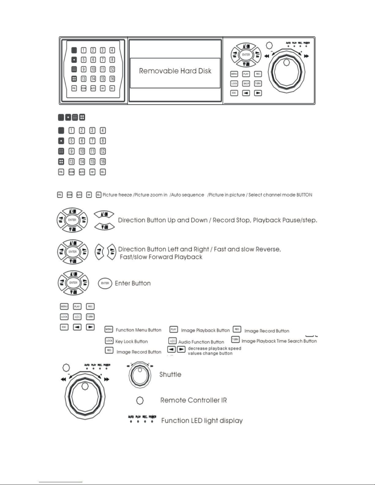
16 Channel DVR Front View
16 / 13 / 9 / 4Channel split screen buttons
1/2/3/4/5/6/7/8/9/10/11/12/13/14/15/16 full screen buttons
5
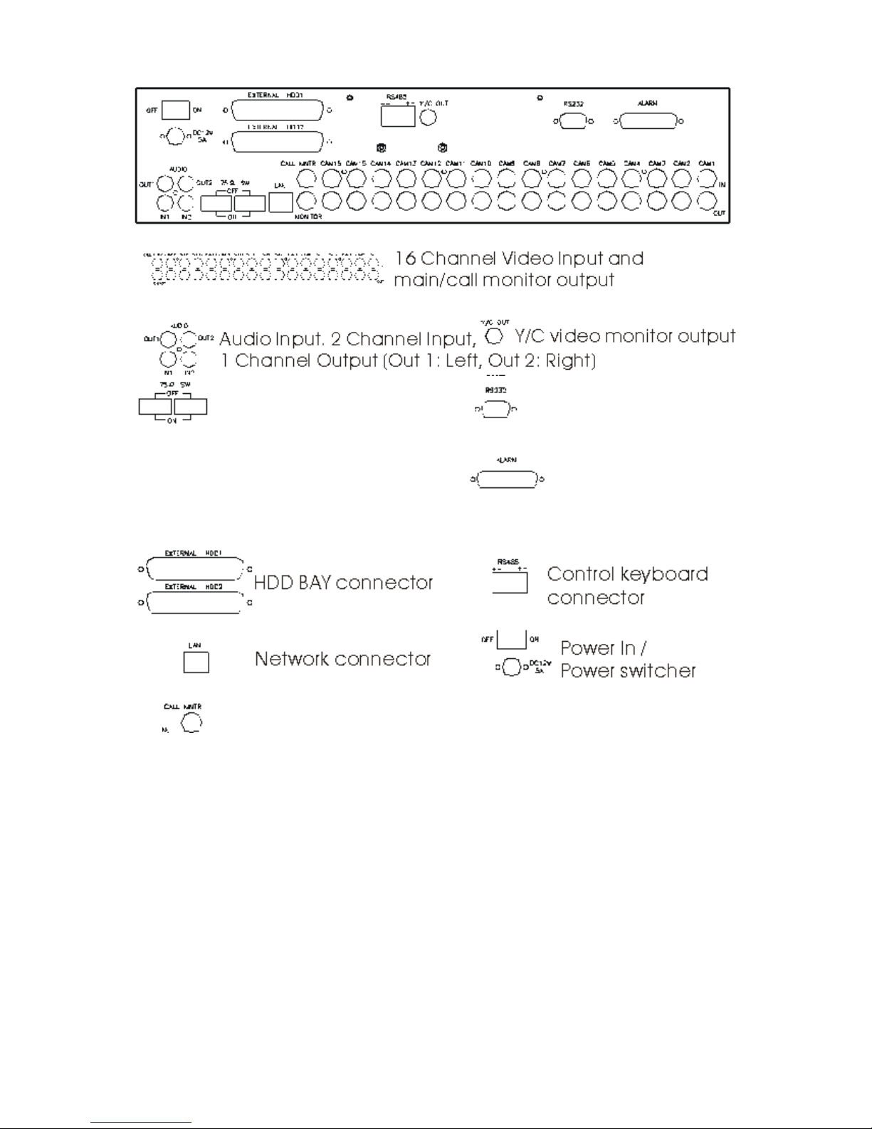
16 Channel DVR Rear View
75 OHM High / Low Adjust RS 232 Connector
Off: channel Loop-out Factory use ONLY!
On: channel Terminated
To adjust the dwell interval, go to System Setup in main menu.
Call Monitor: Sequences through all channels used.
Alarm Connector
6
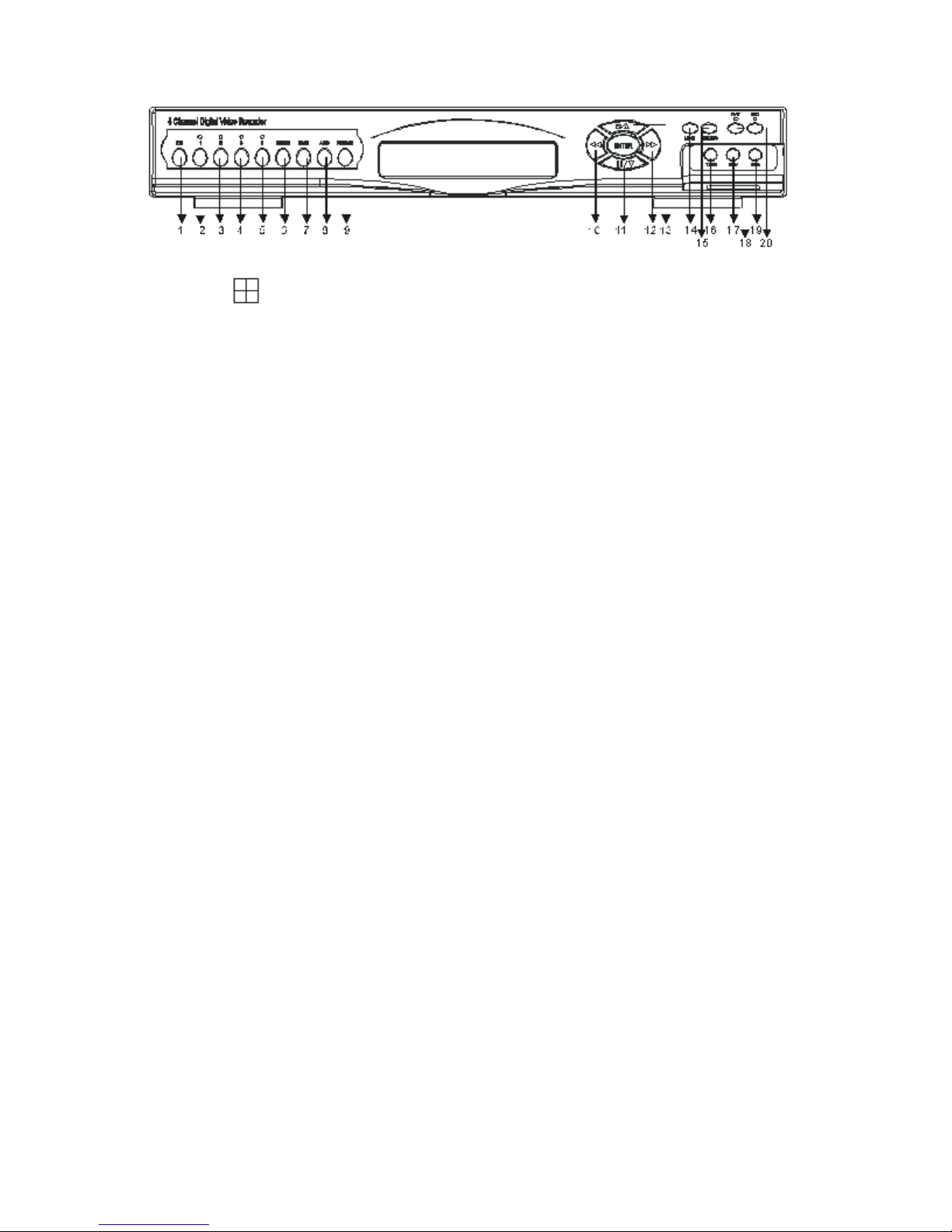
4 Channel DVR Front View
1.
: 4 quad split screen mode button
2. CHANNEL 1: Channel 1 full screen button
3. CHANNEL 2: Channel 2 full screen button
4. CHANNEL 3: Channel 3 full screen button
5. CHANNEL 4: Channel 4 full screen button
6. FREEZE: Picture freeze mode button
7. ZOOM: Picture zoom in mode button
8. AUTO: Auto sequence mode
9. PIP: Picture in picture mode button
10. REW: Reverse playback choose button
11. STEP/DOWN: Playback pause/Direction button down
12. FF: Forward playback choose button
13. STOP/UP: Press this button to stop playback/Direction button up
14. MENU BUTTON: Press this button to display the menu setup
15. LOCK/ESC: Press this button to Lock function
16. T-SRH: Press this button to playback time search
17. DIRECTION/VALUE CHANGE BUTTON: Playback speed choose
(increase)
18. PLAY BUTTON: Press this button to playback
19. DIRECTION/VALUE CHANGE BUTTON: Playback speed choose
(reduce)
20. REC BUTTON: Press this button to start recording image
7
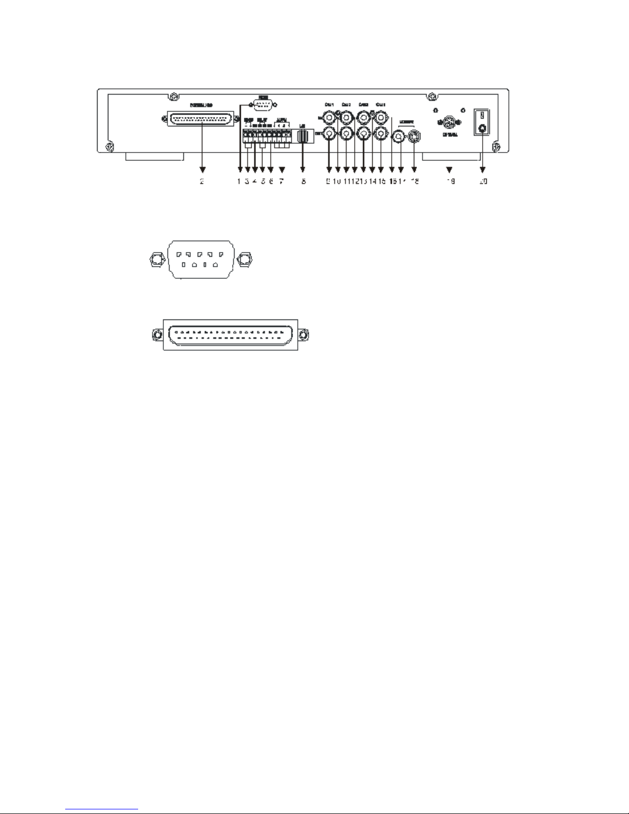
4 Channel DVR Rear View
1. RS-232 IN: FACTORY USE ONLY!
2. EXTERNAL HDD: External IDE HDD bay connector
3. RS-485: RS485 Connector +/-
4. COM:
5. RELAY: Sensor, relay output
6. GND
7. ALARM: Alarm I/O input
8. LAN: Network Connector
9. CAMERA OUTPUT: CAMERA 1 Video image output
10. CAMERA INPUT: CAMERA 1 Video image input
11. CAMERA OUTPUT: CAMERA 2 Video image output
12. CAMERA INPUT: CAMERA 2 Video image input
13. CAMERA OUTPUT: CAMERA 3 Video image output
14. CAMERA INPUT: CAMERA 3 Video image input
15. CAMERA OUTPUT: CAMERA 4 Video image output
16. CAMERA INPUT: CAMERA 4 Video image input
17. MONITOR BNC: Monitor video BNC Connector
18. MONITOR S-VIDEO: Monitor S-Video Connector
19. DC 12V/5A: Power Input
20. POWER: Power Switch ON/OFF
8
The Clinton DVR
The User Manual is created to help you quickly and efficiently install the Clinton
DVR and its most commonly used features. It is important to follow each step in
order and read the instructions carefully to ensure proper programming of the DVR
unit.
It is also important to know the end-user’s requirements in setting up the proper
recording schedules. More detailed information on the other features of the DVR
are located in the DVR Manual, Located on the remote software CD which was
shipped with the DVR.
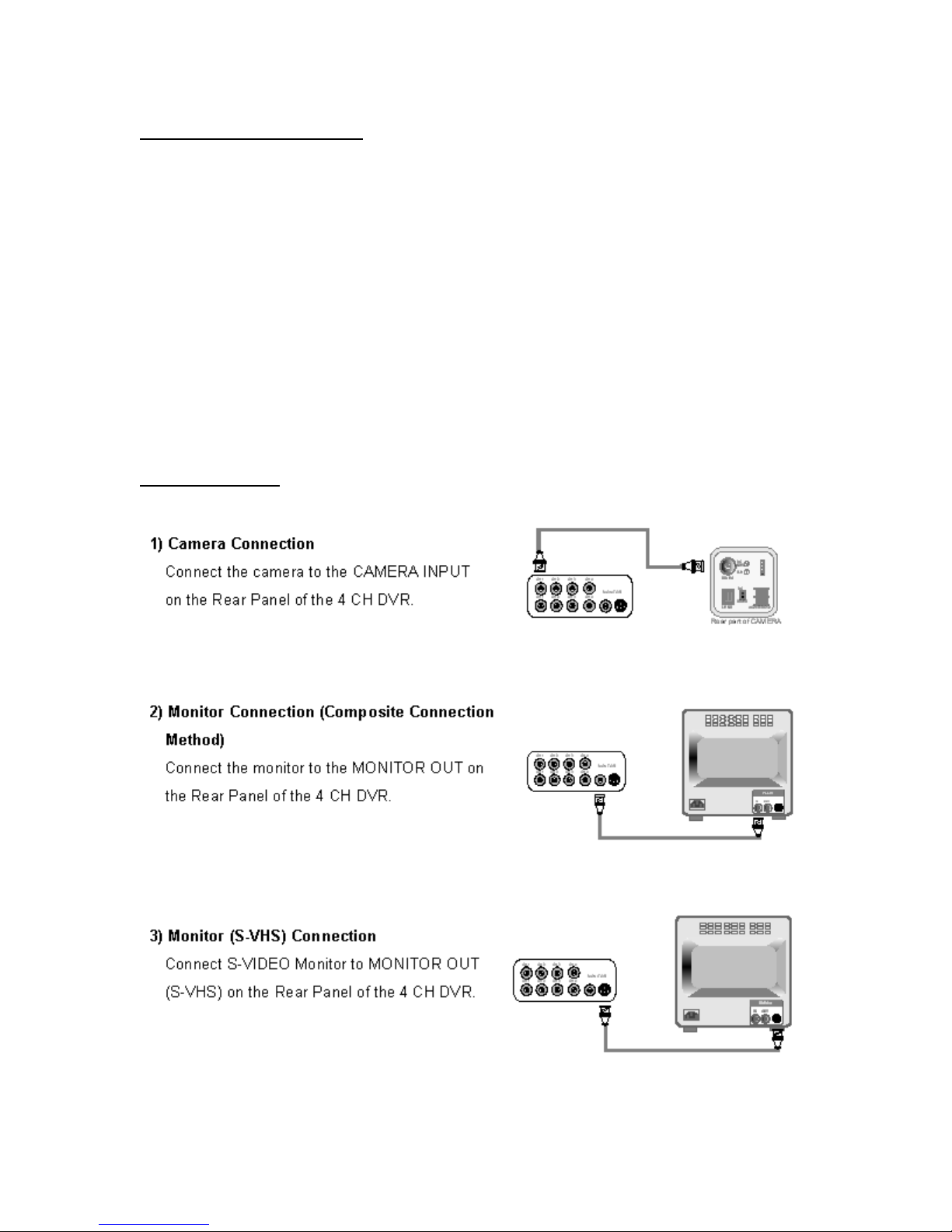
Installation
9
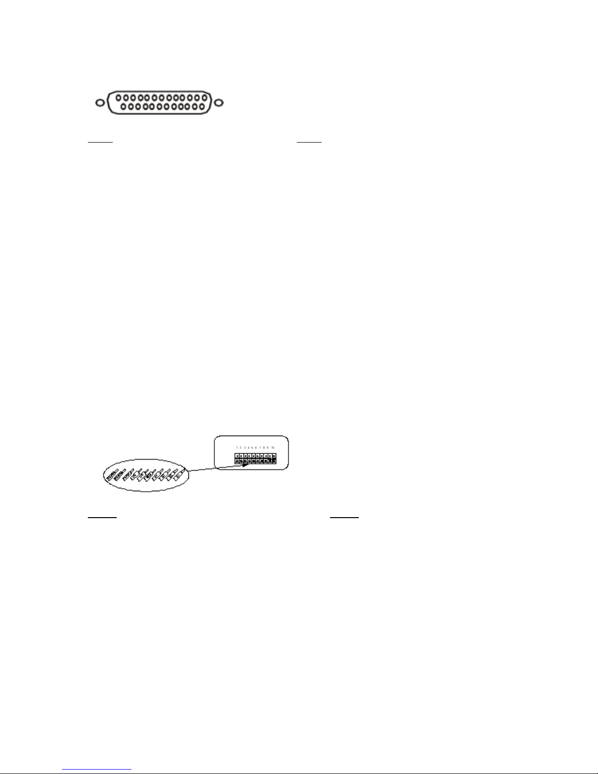
16 Channel DVR Sensor/Alarm Connections:
13,12,11,10,9,8,7,6,5,4,3,2,1
25,24,23,22,21,20,19,18,17,16,15,14
Pin# Pin#
1. ALARM SENSOR 1 14. ALARM SENSOR 14
2. ALARM SENSOR 2 15. ALARM SENSOR 15
3. ALARM SENSOR 3 16. ALARM SENSOR 16
4. ALARM SENSOR 4 17. ALARM/MOTION RELAY #2 COM
5. ALARM SENSOR 5 18. ALARM SENSOR GND
6. ALARM SENSOR 6 19. ALARM SENSOR GND
7. ALARM SENSOR 7 20. ALARM SENSOR GND
8. ALARM SENSOR 8 21. ALARM/MOTION RELAY #1 N.C.
9. ALARM SENSOR 9 22. ALARM/MOTION RELAY #1 COM
10. ALARMSENSOR 10 23. ALARM/MOTION RELAY #1 N.O.
11. ALARM SENSOR 11 24. ALARM/MOTION RELAY #2 N.C.
12. ALARM SENSOR 12 25. ALARM/MOTION RELAY #2 N.O.
13. ALARM SENSOR 13
4Channel DVR Sensor/Alarm Connections:
Pin# Pin#
1. RS 485 - 6. ALARM SENSOR GND
2. RS 485 + 7. ALARM SENSOR 1
3. ALARM/MOTION RELAY COM 8. ALARM SENSOR 2
4. ALARM/MOTION RELAY N.C. 9. ALARM SENSOR 3
5. ALARM/MOTION RELAY N.O. 10. ALARM SENSOR 4
♦Alarm Input: Short-circuit between any alarm sensor and ALARM SENSOR
GND is recognized as alarm.
10
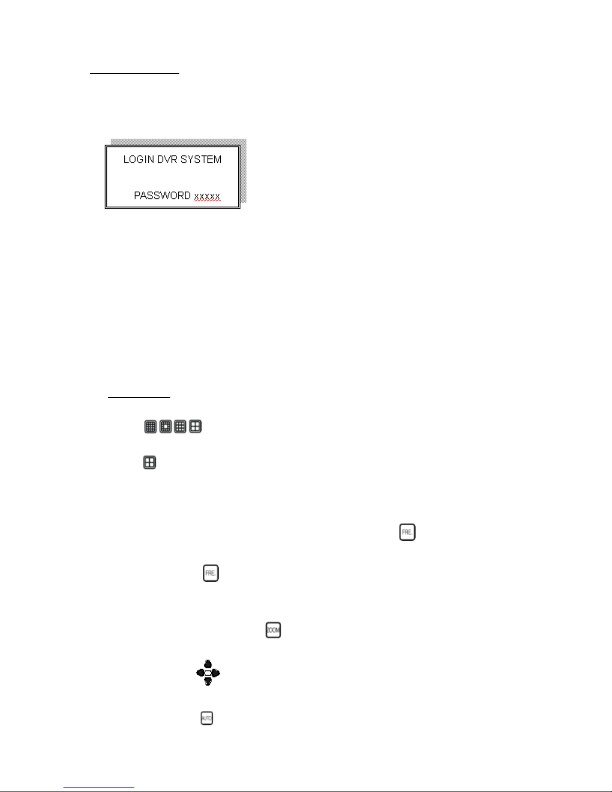
Logging In
1. Press the MENU button to enter into the system.
2. Password enter window pops up:
Password (Account-Admin): 44444
Password (Account-User): 11111
3. Press Numeric button to choose password and unlock the system.
Notice:
1. ADMIN level can setup all menu functions.
2. USER level cannot setup ADVANCED page.
Picture
Full screen or channel split screen display
Press
16channel DVR.
Press
quad button to display 4channel split screen on the 4 channel DVR.
Press numeric buttons to display the desired camera image in full screen.
1.) FREEZE Mode
In live, quad, and full screen mode press
freeze image.
Press
2.) ZOOM Mode (Display Enlargement)
Go to full screen mode with numeric buttons in live or playback
mode, than press
button to display 16 / 13 / 9 / 4 channel split screen on the
(FREEZE) button to
again to cancel freeze mode.
to display screen enlargement.
Use
3.) AUTO Mode
Press
buttons to move position of zoomed picture.
(AUTO) button to begin screen auto sequence.
11

>No auto sequence in 16 / 13 split screen.
>You can activate auto sequence function in 9-spit, 4-split, PIP or
full-screen mode. The 3
nd
2
channel will sequence in 4-split screen mode.
rd
channel will sequence in 9-split screen.
4.) PIP (Picture in Picture)
Press
Use
Button
button, to select the main channel screen, press button
to select desired camera channel in small view (PIP).
5.) SEL (select) 16 Channel ONLY!
>On 13 / 9 / 4 split screen, pressing SEL can change the channel
order.
6.) KEY LOCK FUNCTION
On the Live or Playback mode, Press
(LOCK)
Only, numeric, freeze, auto, pip, and zoom buttons will work. Press
lock key again to enter the log-in window. Enter admin or user
password to unlock.
7.) AUDIO BUTTON
Notice:
1>Recording is stopped during playback.
2>Recording is not possible if camera is not connected.
3>DVR must not be in the PLAY mode, if the user wants to use
remote view.
4>DVR
must be in Live/Record mode to use remote view.
12
Playback
1. Press button to begin playback.
(System will begin playback of the images, backwards from the most recent time.)
Time-Search(T-SRH)
1. Press T-SRH button to activate playback function
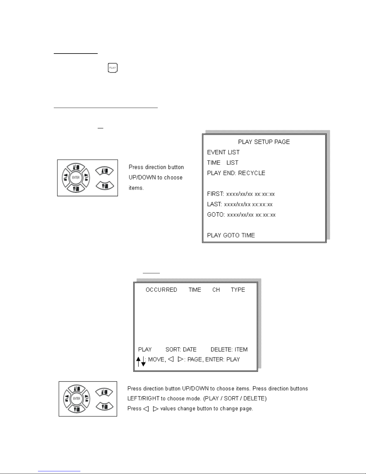
2. Event List (Alarm List): Event source- Video loss/Alarm Trigger
NOTE: Does
NOT record motion events.
PLAY: Press ENTER to start Playback.
13
SORT: (16 Channel Only) DATE, alarm events sort by date and time.
CH, alarm events sort by channel.
TYPE, alarm events sort by type.
Press (SEL)
button to change sort.
DELETE: (16 Channel Only) ITEM-deletes line items. PAGE-deletes each page.
ALL-deletes all items.
Press (SEL)
button to change delete mode.
(4 Channel Only) SORT: Sorts by date only.
(4 Channel Only) DELETE: Deletes by line item only.
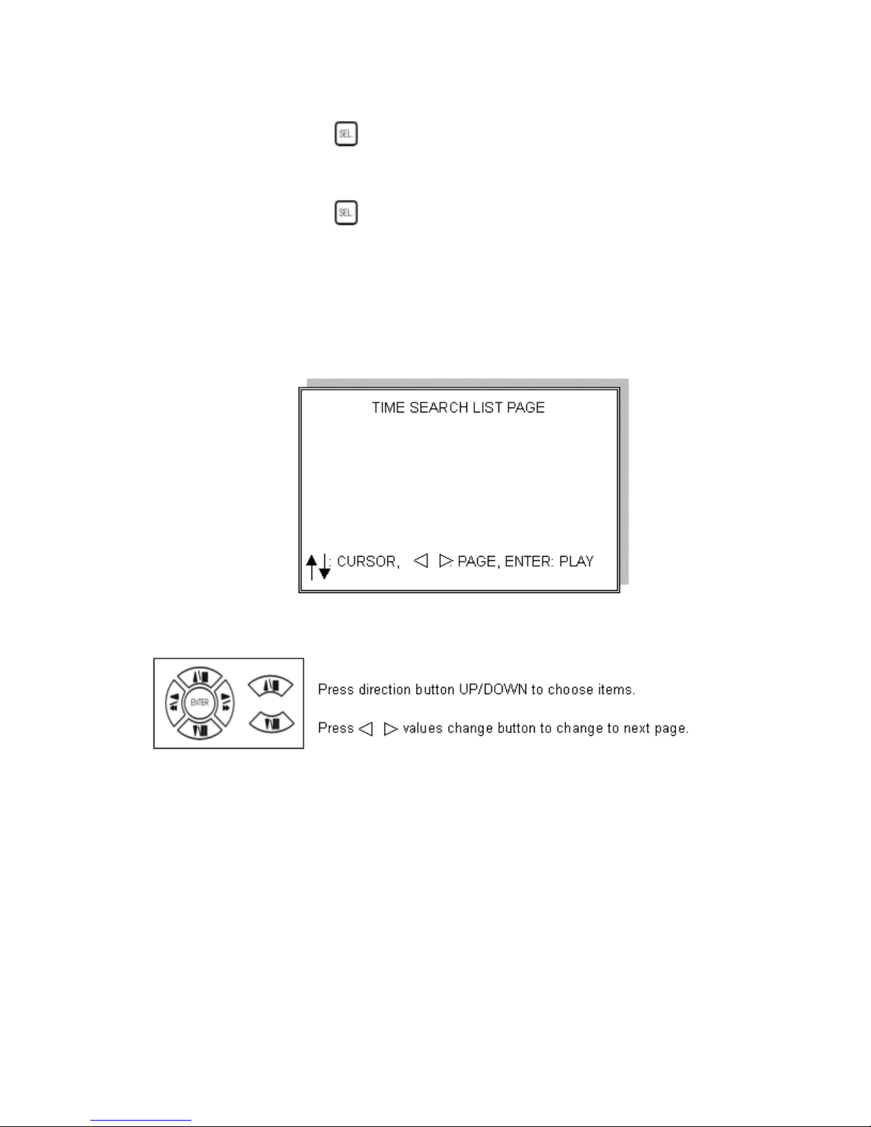
3. TIME LIST (Playback image by Time-Search): Recorded image list (by hours)
No items or page display limit. DVR recording mode is continuous.
PLAY END: After selected image playback ends, DVR is going to continue to
playback this file. Press STOP to stop playback, press RECORD to continue
recording.
FIRST: XXXX/XX/XX XX:XX:XX (The first date and time recording display)
If HDD has overwritten, the first date and time displayed will change.
LAST: XXXX/XX/XX XX:XX:XX (The final date and time recording
displayed). When the user stops recording or goes to a menu, at that moment is the
last record.
GO TO: XXXX/XX/XX XX:XX:XX Enter the (year / month / day, hour /
minute / second) of selected viewing time.
PLAY GO TO TIME: After entering date and time, select PLAY GOTO TIME,
press ENTER to start playback.
14
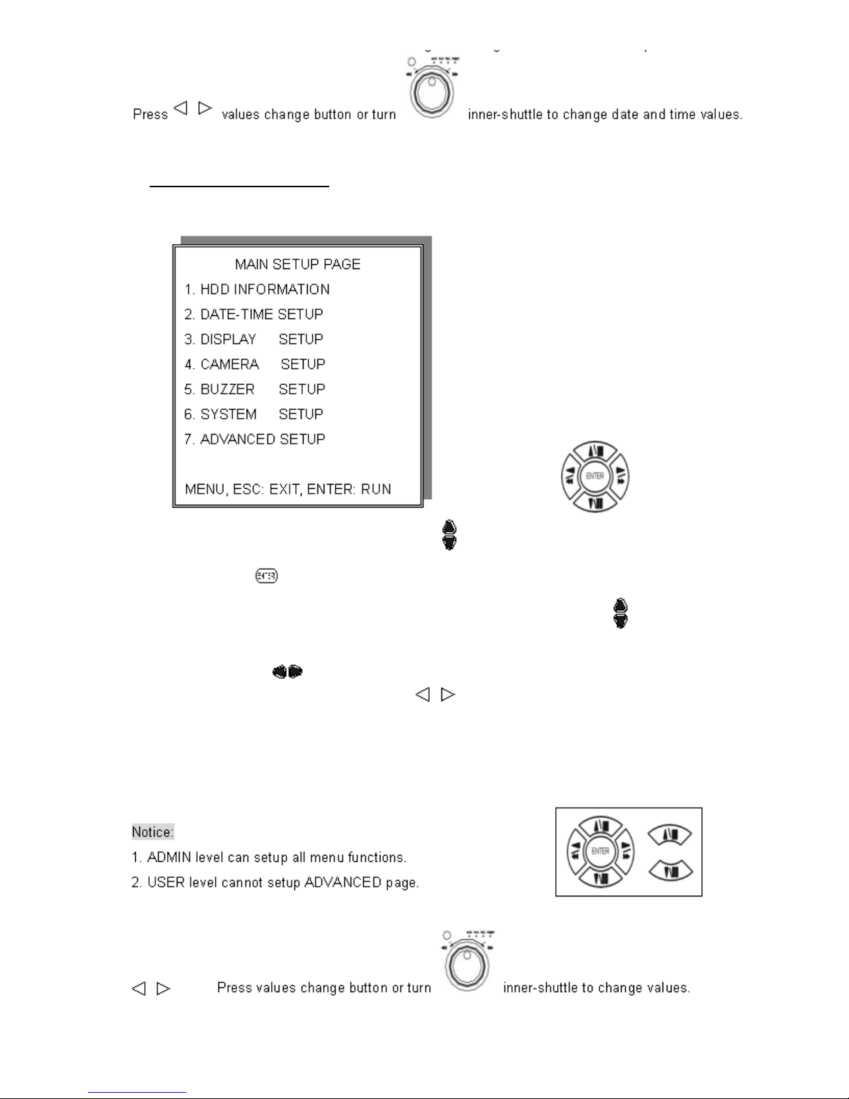
Basic Operation
Press MENU button to enter MAIN SETUP PAGE
1. Use direction button up/down
to select setup item.
2. Press
3. Press sub-menu item with direction button up/down
Or left/right
And change the value with the
4. Press ESC/LOCK button to go back to Main Menu or Exit.
button to enter into sub-menu function.
button.
values change buttons.
15
 Loading...