

Clinton 8890BH Service Manual
ML8890BH-7
CLINT ON
MODEL 8890BH
PROGRAMMABLE CONTROLLER
DRIVE SYSTEM
FOR
DURKOPP 558
BUTTONHOLE MACHINE
SERVICE MANUAL
Para Español vea el reverso del libro
40-0240-01

ML8890BH-8
TABLE OF CONTENTS
SECTION I - DESCRIPTION . . . . . . . . . . . . . . . . . . . . . . . . . . . . . . . . . . . . . . . . 1-1
SECTION II - INSTALLATION . . . . . . . . . . . . . . . . . . . . . . . . . . . . . . . . . . . . . . . . 2-1
DRIVE PULLEY . . . . . . . . . . . . . . . . . . . . . . . . . . . . . . . . . . . .
A.
SYNCHRONIZER & SENSOR . . . . . . . . . . . . . . . . . . . . . . . . . .
B.
SEWING HEAD DRIVE PULLEY . . . . . . . . . . . . . . . . . . . . . . . .
C.
START SWITCH . . . . . . . . . . . . . . . . . . . . . . . . . . . . . . . . . . . .
D.
AIR CYLINDER . . . . . . . . . . . . . . . . . . . . . . . . . . . . . . . . . . . . .
E.
UPPER MOTOR . . . . . . . . . . . . . . . . . . . . . . . . . . . . . . . . . . . .
F.
EMERGENCY STOP SWITCH . . . . . . . . . . . . . . . . . . . . . . . . .
G.
SECTION III - ADJUSTMENTS INSTRUCTIONS . . . . . . . . . . . . . . . . . . . . . . . . . . 3-1
HOME POSITION . . . . . . . . . . . . . . . . . . . . . . . . . . . . . . . . . . .
A.
FIRST STITCH POSITION . . . . . . . . . . . . . . . . . . . . . . . . . . . .
B.
NEEDLE UP POSITION . . . . . . . . . . . . . . . . . . . . . . . . . . . . .
C.
MOTOR FUNCTION & SENSOR TEST . . . . . . . . . . . . . . . . . .
D.
TENSION RELEASE . . . . . . . . . . . . . . . . . . . . . . . . . . . . . . . . .
E.
SWING KNIFE & LOOPER THREAD TRAPPER . . . . . . . . . . . .
F.
THREAD NIPPER . . . . . . . . . . . . . . . . . . . . . . . . . . . . . . . . . . .
G.
SECTION IV - MODES OF OPERATION . . . . . . . . . . . . . . . . . . . . . . . . . . . . . . . . . 4-1
FULL CYCLE . . . . . . . . . . . . . . . . . . . . . . . . . . . . . . . . . . . . . . .
A.
SINGLE STEP . . . . . . . . . . . . . . . . . . . . . . . . . . . . . . . . . . . . . .
B.
MOVE TABLE ONLY . . . . . . . . . . . . . . . . . . . . . . . . . . . . . . . . .
C.
REPAIR CYCLE . . . . . . . . . . . . . . . . . . . . . . . . . . . . . . . . . . . . .
D.
2-1
2-2
2-3
2-4
2-4
2-5
2-5
3-1
3-1
3-1
3-2
3-2
3-2
3-3
4-1
4-2
4-2
4-2
SECTION V - PROGRAMMING MODE . . . . . . . . . . . . . . . . . . . . . . . . . . . . . . . . . . 5-1
HOW TO PROGRAM . . . . . . . . . . . . . . . . . . . . . . . . . . . . . . . .
A.
ACCESS TO HIDDEN PARAMETERS . . . . . . . . . . . . . . . . . . .
B.
MASTER RESET . . . . . . . . . . . . . . . . . . . . . . . . . . . . . . . . . . . .
C.
EXPLANATION OF PARAMETERS . . . . . . . . . . . . . . . . . . . . .
D.
1.
2.
3.
4.
5.
E. PARAMETER LIST . . . . . . . . . . . . . . . . . . . . . . . . . . . . . . . . . . 5-6
SECTION VI - TEST MODE . . . . . . . . . . . . . . . . . . . . . . . . . . . . . . . . . . . . . . . . . . . 6-1
BUILT-IN TEST PROGRAM . . . . . . . . . . . . . . . . . . . . . . . . . . .
A.
TESTING THE HOME AND SEW SENSORS . . . . . . . . . . . . .
B.
TESTING THE CLAMP DOWN AND START SWITCHES . . . .
C.
TESTING THE MOTORS . . . . . . . . . . . . . . . . . . . . . . . . . . . . .
D.
EXITING THE TEST MODE . . . . . . . . . . . . . . . . . . . . . . . . . . .
E.
DESCRIPTION OF THE HOME AND SEW SENSOR BLOCKS
F.
USING THE EMERGENCY STOP BUTTON . . . . . . . . . . . . . .
G.
AIR PRESSURE SWITCH . . . . . . . . . . . . . . . . . . . . . . . . . . . . .
H.
PARAMETERS WITH DIRECT ACCESS . . . . . . . . . . . . .
TIMERS . . . . . . . . . . . . . . . . . . . . . . . . . . . . . . . . . . . . . . .
COUNTERS . . . . . . . . . . . . . . . . . . . . . . . . . . . . . . . . . . . .
TOGGLE SWITCHES . . . . . . . . . . . . . . . . . . . . . . . . . . . .
HIDDEN PARAMETERS . . . . . . . . . . . . . . . . . . . . . . . . . .
5-1
5-1
5-2
5-2
5-2
5-2
5-3
5-3
5-4
6-1
6-1
6-1
6-1
6-2
6-2
6-3
6-3

ML8890BH-9B
SECTION I
DESCRIPTION
The Clinton Model 8890BH is a Micro Computer Controlled Electro / Mechanized / Pneumatic
system designed to enhance the performance and drastically reduce the maintenance required
to operate a Durkopp Buttonhole machine.
Two DC Servo Motors are used to replace the complete mechanized stop motion components
including the clutch, brake, spur gears and shafts.
State of the art sensors are used to communicate position and speed data to the single micro
computer control system. By use of the LCD Programmable Display, both the machine speed
and buttonhole "Eye" speed can be precisely entered and controlled. The LCD can also be used
to command repair cycles or 3 step cycles to assist in machine maintenance.
Figure 1-1 shows the major components of the system.
STOP
SWITCH
START
SWITCH
UPPER MOTOR
NEEDLE-UPSENSOR
SENSOR
ASSEMBL Y
LCD DISPLA Y
FIG. 1-1
1-1
LCD POST
ASSEMBLY
ML8890BH-10
SECTION II
INSTALLATION
Insure that the machine is in working order.
Mark the home position.
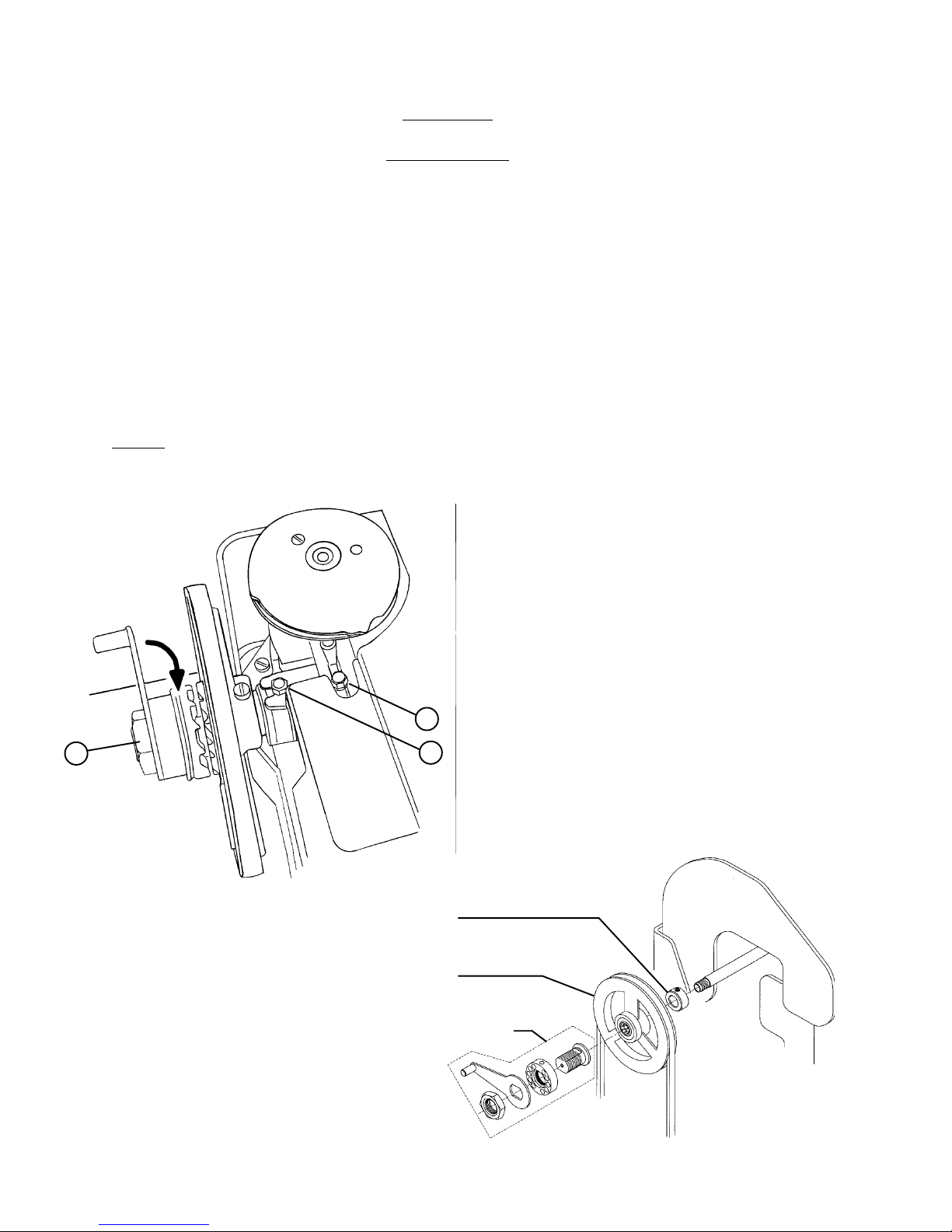
A. To install the drive pulley assembly. Remove the manual crank mechanism by rotating the crank
in the clockwise direction (See Fig. 2-1). Remove the pulley carrier assembly by loosening the hex
nut which attaches it to the reversing lever (Fig. 2-1, Item 1) and sliding the entire assembly off the
end of the cross shaft. Remove the large hex nut which holds the manual crank onto the crank hub
(Fig. 2-1, Item 2). Remove all parts from the crank hub. Loosen hex head screw (Fig. 2-1, Item 3)
and slide it toward the operator as far as it will travel in it’s adjusting slot. Place collar (02-4007-01)
and pulley assembly (10-1457-01) on the end of the cross shaft (See Fig. 2-2).
NOTE: The pulley assembly contains a locking bearing, insure that the bearing locks and drives
the shaft in the counterclockwise direction and free-wheels in the clockwise direction. Replace
the crank hub, spring holding device, manual crank and retaining nut (Fig. 2-2).
ROTATE
CLOCKWISE
TO REMOVE
2
3
1
FIG. 2-1
02-4007-01
COLLAR
10-1457-01
PULLEY ASS'Y
EXISTING
CRANK
FIG. 2-2
2-1
ML8890BH-11A
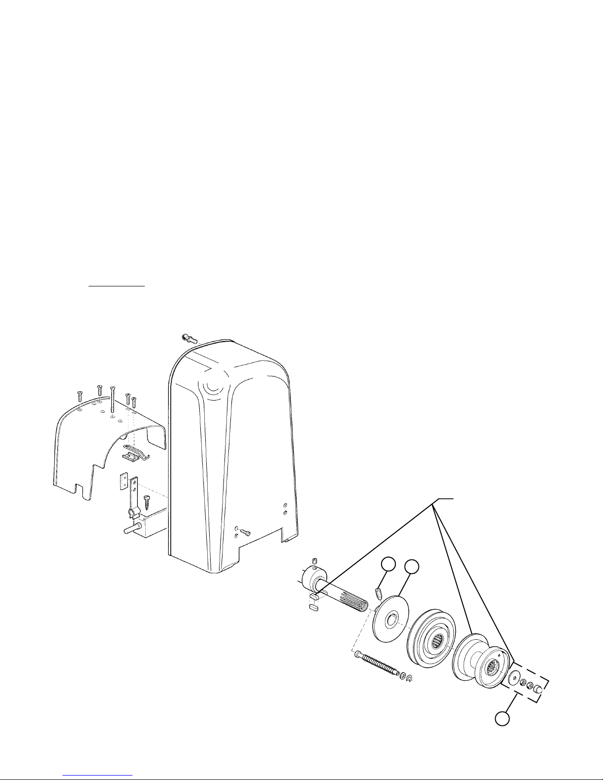
B. To install the synchronizer and sensor assemblies. Remove cover assemblies (Fig. 2-3).
Remove the hand wheel and sewing head pulley by removing the two locking nuts (Fig. 2-4,
Item 1). Remove the stop motion eccentric (Fig. 2-4, Item 2) by removing the threaded stud
(Fig. 2-4, Item 3). Retain thehand wheel, washer and locking nuts so that they may be put back
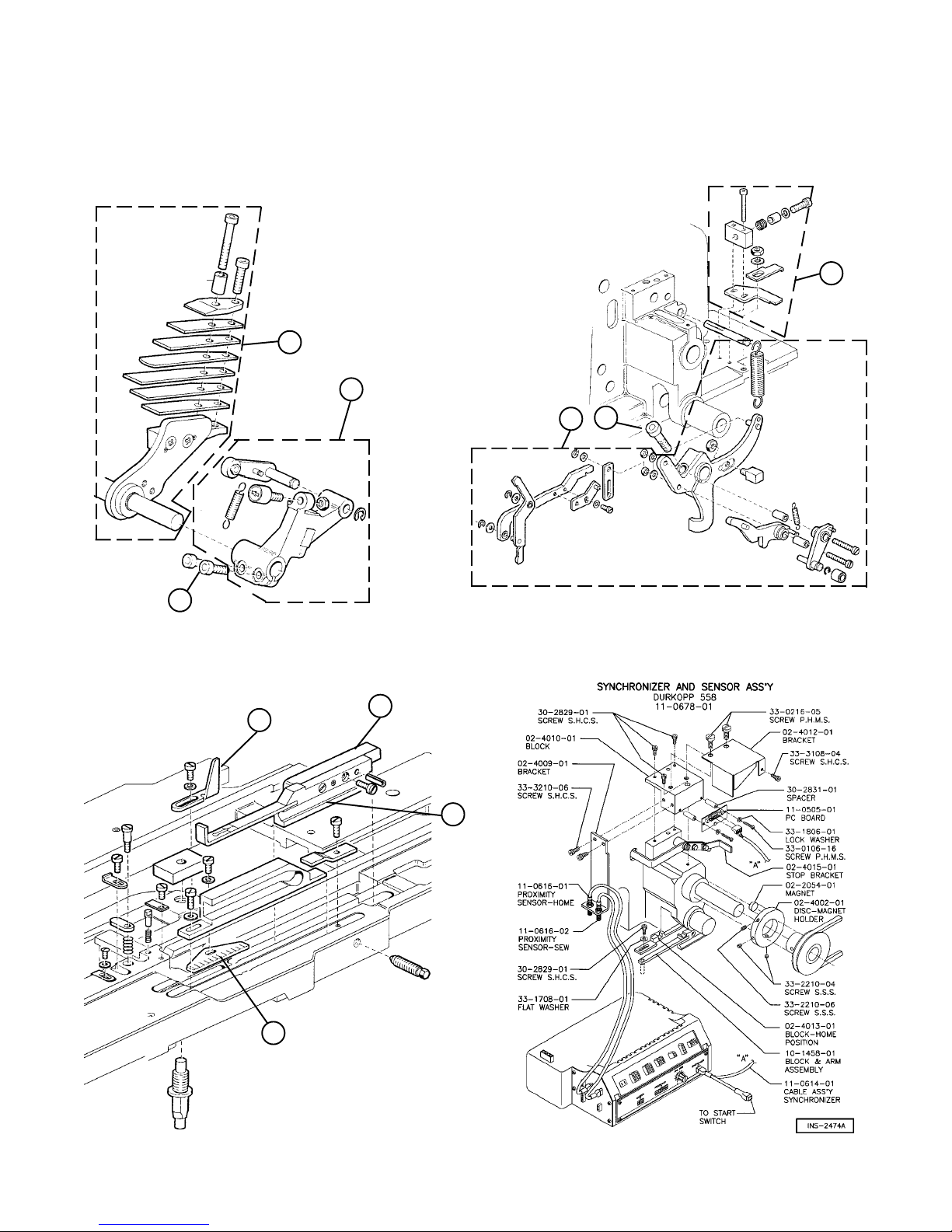
on at a later time. Remove the stop motion roller assembly (Fig. 2-5, Item 1) by loosening the two
clamp screws (Fig. 2-5 , Item 2). Manually rotate the machine to it’s furthest foreword point (half
way around the eye). Remove the stop motion leaf spring assembly (Fig. 2-5, Item 3) and three
forks lever by loosening the clamp screw (Fig. 2-6, Item 2) and sliding the leaf spring shaft out of
the casting. Remove torsion spring assembly (Fig. 2-6, Item 1). Remove the length adjusting slide,
stop and gauge plate (Fig. 2-7, Items 1, 2, & 3). Remove the tension release block (Fig. 2-7,
Item 4)from the length adjusting slide and attach it to the first stitch sensor block (Fig. 2-8,
10-1458-01). Replace the length adjusting slide with the first stitch sensor block. Using the screw
provided install the home position sensor block (Fig. 2-8, 02-4008-01) and stop bracket (Fig. 2-8,
02-4015-01). Using the screws provided install the sensor block assembly (Fig. 2-8).
WARNING: Insure that there is at least 1/16th of an inch clearance between bottom of
thehome and sew sensors and the home position and first stitch blocks
(Fig. 2-9) so that no damage is caused to the sensors when the machine is
cycled.
FIG. 2-3
2-2
3
FIG. 2-4
RETAIN FOR
REINSTALLATION
2
1
ML8890BH-12A
C. To install the sewing head drive pulley assembly. Attach the magnet disk holder to the sewing
head pulley (Fig. 2-8). Slide the pulley onto the arm shaft. Replace the hand wheel, washer and
locking nuts (Fig. 2-4).
3
3
1
2
1
2
FIG. 2-5
FIG. 2-6
4
2
1
3
FIG. 2-7 FIG. 2-8
2-3
ML8890BH-13A
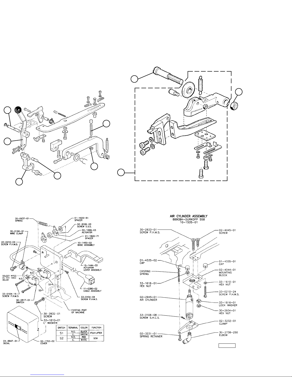
D. To install the start switch assembly. Remove the hand lever and clamping angle
(Fig. 2-9, Item 1 & 2) by removing the two pivot pins (Fig. 2-9, Item 3 & 4). Remove the manual
start switch (Fig. 2-9, Item 5). Remove the stop stud and locking nut (Fig. 2-9, Item 6 & 7).
Remove the clamping lever (Fig. 2-10, Item 1) by removing the lock nut and pivot bolt (Fig. 2-10,
Item 2 & 3). Install the start switch. (See Fig. 2-12).
3
3
6
1
2
7
4
1
2
FIG. 2-9
E. To install the air cylinder assembly. See Fig. 2-12.
FIG. 2-10
FIG. 2-11
INS-2594
FIG. 2-12
2-4
ML8890BH-14
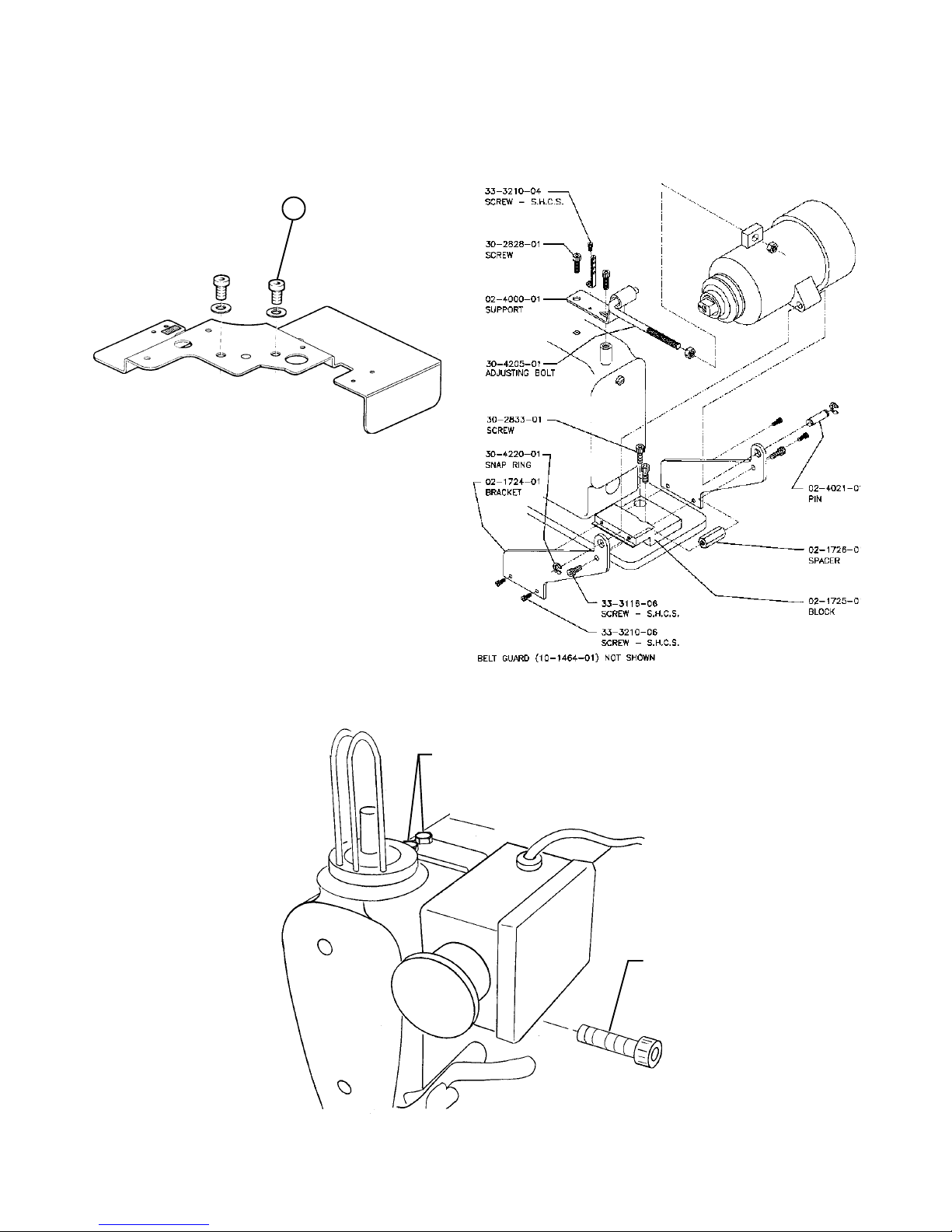
F. To install the Upper Motor. Remove the two cover retaining screws (Fig. 2-13, Item 1), and using
the screws provided install the upper motor (See Fig. 2-14).
1
FIG. 2-13
FIG. 2-14
G. To install the Emergency Stop Switch. Use the screws provided and install as shown
(See Fig. 2-15).
MOUNTING
SCREWS
MOUNTING
SCREW
FIG. 2-15
2-5

ML8890BH-15
SECTION III
ADJUSTMENT INSTRUCTIONS
Remove the needle.
A. T o set the Home Position. Return the machine to the home position by rotating the
manual crank until the arrows on the home position labels are aligned. Making sure that
the air supply is disconnected turn the power on. Loosening the home position block
retaining screw (Fig. 2-8) and slide the home position block toward the rear of the machine
as far as the adjusting slot will allow. Slowly pull the home position block toward the
operator until the indicator light on the home position sensor goes out. Gently push the
home position block toward the rear of the machine until the indicator light again comes on.
Tighten the retaining screw .
B. T o s e t the first stitch position. Rotate the machine with the manual crank until the leading
edge of the material clamp is aligned with the needle. Loosen the first stitch sensor block
retain screw and push the stitch sensor block toward the rear of the machine as far as it will
travel. Pull the first stitch sensor block toward the operator until the indicator light on the
first stitch sensor comes on. Tighten the retaining screw . Return the machine to the home
position.
C. T o set the needle up position. Rotate the hand wheel until the needle bar is at to dead
center with the left hand looper at the extreme left hand end of it’s stroke. With the
machine in this position loosen the set screws on the magnet disk. Rotate the magnet disk
until the magnet is aligned with the magnet sensor on the synchronizer board and as close
as possible to it without touching. Tighten the set screws.
Connect the air supply .
CAUTION: With the air supply now connected the machine will cycle if the start
switch is depressed.
3-1
 Loading...