

Clinton 323A Instruction Manual And Parts List
CLIITTOII
CHI1INSf,IUS
REPTACEMENT
ENGINE
..$,
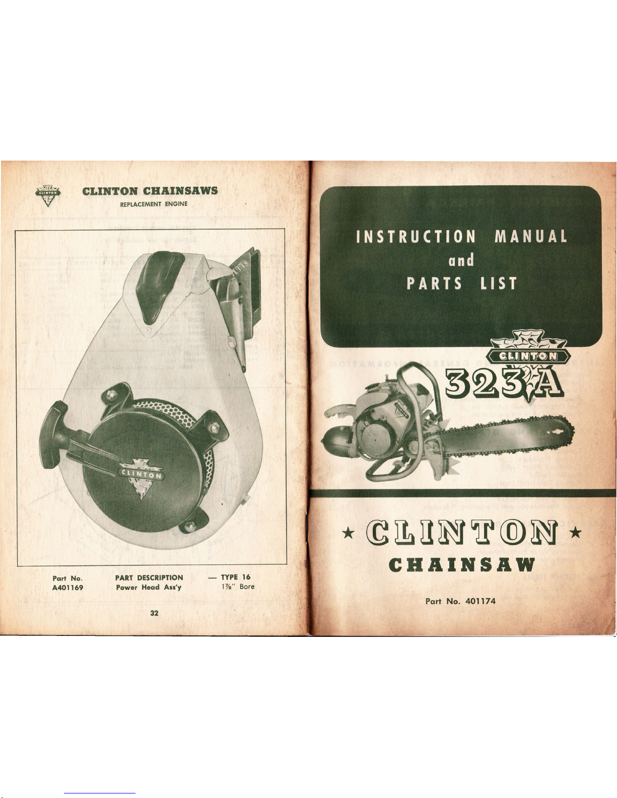
Port No.
A40t t69
PART DESCRIPTION
Power
Heod
Atst
92
-
IYPE
16
l7/a" Bore
*
GL[N$T@N$
*
GHAINSAW
Pqrf No. 40ll74
INSTRUCTION
TJIANUAL
0nd
PARTS tIST
/
By
following the
instructions in this
manual
you
can
look forward
to de-
pendable
service from
your
Chainsaw.
Quality
made, time tested Clinton
Chainsaws are
designed to
provide
ef-
ficient cutting on a
great
variety
of
jobs.
They
are
checked for high stand-
ards during all
phases
of
production
and assembly.
Treat
your
Chainsaw
right, and it will become the most valu-
able
tool
you
own.
For
periodic
servicing
and all
major
repairs,
you
should consult the Author-
ized
Clinton
Service Station
in
your
area. Here
you
will
find
factory-trained
mechanics,
genuine
Clinton
parts
and
prompt,
efficient service at
your
dis-
posal.
There
are Clinton
Service Sta-
tions
throughout the United States,
Canada and
many foreign countries.
Consult
the
yellow
pages
of
your
tele-
phone
directory for list
of Authorized
Clinton Service Stations.
For additional information about
your
Clinton Chainsaw
please
feel free
to write directly
to the factbry.
INTRODUCTION
AND
GENERAT
INFORMATION
lntroduction
SERVICE DEPARTMENT
CHAINSAW DIVISION
CTINTON MACHINE
COMPANY
CLINTON, MICHIGAN
Specif
ications
Princip.le
of
2-Cycle
Engine
Operation
Assembly
of
Guide
Bar
and
ihipper
Chain.
.
3
3
4
5
6
6
Fuel
Preparation
and
Lubrication
Chain
and
Guide
Bar
Lubrication
STARTING
AND
OPERATING
PROCEDURE
Sofety.
Precoutions
Controls
Storting
Procedure
Corburetor
(Floot
Type)
Break-ln
Period
Bucking
Cut-Small
Logs
N.otching
and
Felling
Cut
SERV!CE
AND
ADJUSTMENTS
Fuel
System
Cleaning
Valve
Ports-Exhaust
Maintenance
ACCESSORY
ITEMS
Bow
Sow
Attochment
Helpers
Handle
Assembly
ENGINE-Clinton two
cycle,
one
cylin-
der, air-cooled.
BORE-I7e
STROKE-15/e inches.
FUEt-Oil and Gasoline mixed.
SPARKPTUG-Champion Hll
or
equal,
Gap .025 inches.
POINT GAP-.020 inches,
nominal set-
ting.
IGNITION TIMING-Fixed.
IYPE OF VALVE*Reed.
OPERATING
SPEED
-
Approximalely
4500 R.P.M.
lDLlNG
SPEED
-
Approximotely
1500
to 1800 R.P.M.
TYPE OF
BEARINGS-Bo||
ond needle
beorings
lhroughout.
TYPE OF
CARBUREIOR
-
Floot.
FUEL
TANK CAPACITY
-
I
quort.
FUEI R.AIIO-3/a
pint
of SAE
#30
to I
gal. gasoline.
RECOMMENDED
GASOLINE
-
Any
good grode
(non-leoded).
RECOMMENDED OIt GRADE
-
SAE
#30
(non-detergent).
TYPE OF
IGNITION
-
Clinlon high
tension fly-wheel mognelo.
TYPE
OF
STARTER-CIinton recoil.
TYPE OF C[UTCH-Automatic
Centri-
f ugal.
CHAIN
OIIER CAPACIIY
-
7z
pint
SAE
#30.
GUIDE
BAR TENGTHS-From l6
inches
to 30 inches
(stroight
guide
bors);
14 & 18
inch
Bow Sow Attqch-
ments ovoiloble.
6
7
8
8,9
8
t0
l0
l0
11,12
l3
r3
l3
I3
t4
r5
currTolt
'cHAtilsAw
INTRODUCT!ON
w
SPECIFICATIONS
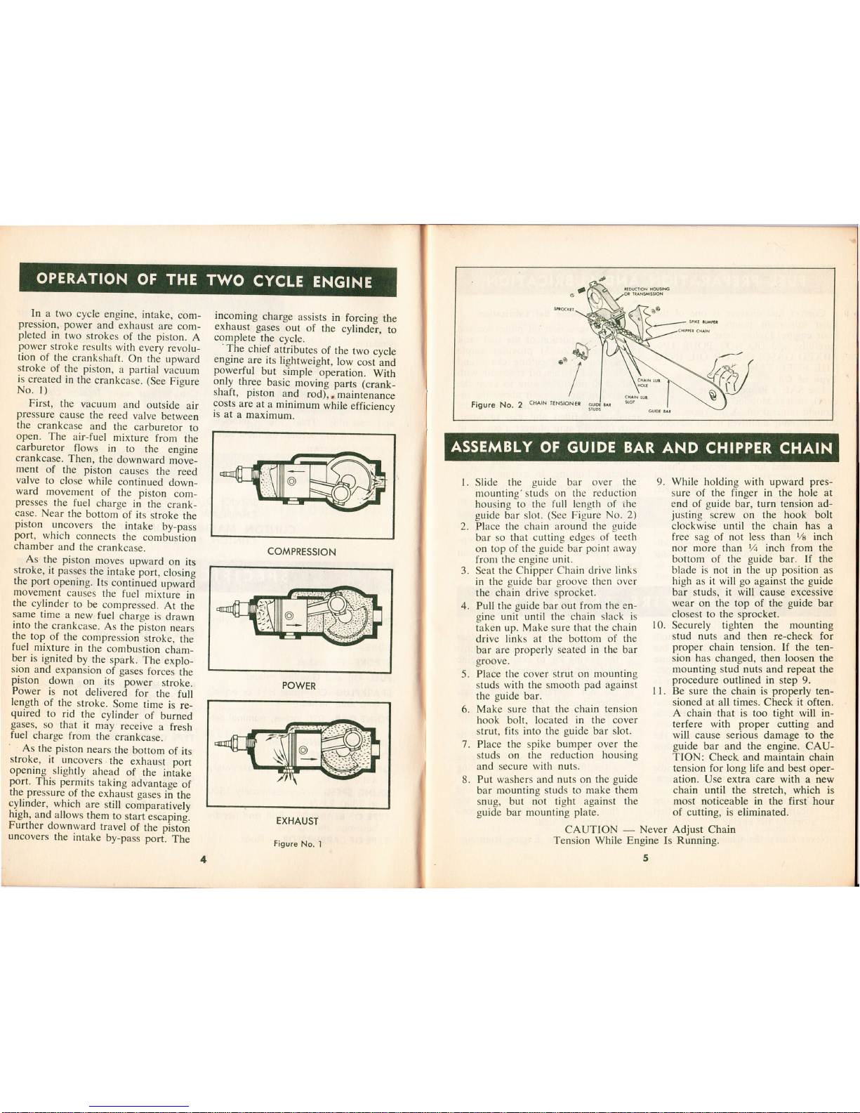
In a
two
cycle
engine,
intake,
com-
pression,
power
and
exhaust
are
com-
pleted
in
two
strokes
of
the piston.
A
power-stroke
results
with
every
revolu_
tion
of
the
crankshaft.
On the
Lrpward
stroke
of
the piston,
a
partial
vacuum
is
created
in
the
crankcase. (See
Figure
No. l)
First,
the
vacuunt
and
outside
air
pressure
cause
the
reed
valve
between
the
crankcase
and
the
carburetor
to
open.
The
air-fuel
mixture
from
the
carburetor
flows
in
to
the
ensine
crankcase.
Then,
the
downward
m6u"-
ment
of
the piston
causes
the
reed
valve
to
close
while
continued
down-
ward
movement
of
the
piston
com_
presses
the
fuel
charge
in
the
crank_
case.
Near
the
bottom
of its
stroke
the
piston
uncovers
the
intake
by-pass
port,
which
connects
the
combirsiion
chamber
and
the
crankcase.
As
the piston
moves
upward
on
its
stroke,
it passes
the
intake
port,
closins
the
port
opening.
Its
continued
,p*arj
movement
causes
the
fuel
mixture
in
the
cylinder
to
be
compressed.
At
the
same
time
a new
fuel
iharge
is
drawn
into
the
crankcase.
As
the
iiston
nears
the
top
of
the
compression
stroke,
the
fuel
nrixture
in
the-combustion
cham_
ber
is
ignited
by the
spark.
The
explo_
sron
and
expansion
of
gases
forces'the
piston
down
on
its
-power
stroke.
Power
is
not
delivered
for
the
full
length
of
the
stroke.
Some
time
is re_
quired
to
rid
the
cylinder
of
burned
gases,
so
that
it
may
receive
a fresh
fuel
charge
l'ronr
the-
crankcase.
'
As the
piston
nears
the
bottom
of its
stroke,
it
uncovers
the
exhaust
oort
opening
slightly
ahead
of
the
iniake
port.
This permits
taking
advantage
of
the. pressure
of
the
exharlst
gases
ii
the
cylinder,
which
are
still
coirparatively
high,
and
allows
them
to
start
escaoins.
Further
downward
travel
of the pisto"n
uncovers
the
intake
by-pass
port.
The
incoming
charge
assists
in
forcing
the
exhaust
gases
out
of
the
cylindei,
to
contplete
the
cycle.
'The
chief
atfributes
of
the
two
cvcle
engine-
are
its
lightweight,
low
cost
ind
powerful
but
simple
operation.
With
only
three
basic
moving
parts (crank_
shaft,
piston
and
rod)],'muirteninc"
costs
are
at
a minimum
while
efficiency
is
at
a
maximum.
Figure
No. 2
cHArN
l Slide the
guide bar over the
mounting'studs
on the reduction
housing
to the full
length of the
guide
bar slot.
(See
Figure No.
2)
Place
the chain around
the
guide
bar so that cutting
edges of teeth
on
top of the
guide
bar
point away
fronr
the engine unit.
Seat
the Chipper
Chain drive links
in the
guide
bar
groove
then over
the chain drive
sprocket.
Pull
the
guide
bar out
from the en-
gine unit until the chain
slack is
taken
up. Make sure that the chain
drive links at the bottom of the
bar are
properly
seated
in
the bar
groove.
Place the cover
strut on mounting
studs
with the smooth
pad
against
the
guide
bar,
Make sure that the chain tension
hook
bolt.
located in
the
cover
strut,
fits into the
guide
bar slot.
7. Place
the
spike
bumper over the
studs on the reduction
housing
and
secure with nuts.
8.
Put washers and
nuts on the
guide
bar mounting
studs to make them
snug,
but not tight against
the
guide bar mounting
plate.
While holding with upward
pres-
sure of the finger
in
the hole
at
end
of guide
bar, turn tension ad-
justing
screw on the hook bolt
clockwise until the chain
has a
free sag of not less than
7e
inch
nor more
lhan
Vt inch from the
bottom of the
guide
bar. lf
the
blade is not in the up
position
as
high as it will go
against
the
guide
bar studs, it
will
cause excessive
wear on the top of the guide bar
closest to the sprocket.
Securely tighten the mounting
stud
nuts
and then re-check for
proper
chain tension.
If the
ten-
sion has
changed,
then
loosen
the
mounting stud nuts and repeat the
procedure
outlined
in
step 9.
Be sure the chain
is properly
ten-
sioned
at all
times.
Check
it
often.
A chain that is
too
tight
rvill
in-
terfere with
proper
cuttin,s
and
rvill
cause serious damage to the
guide
bar and the engine. CAU-
TION:
Check and
maintain
chain
tension for
long life and best oper-
ation. Use extra care with a new
chain until the stretch, which
is
most noticeable in the
first' hour
of
cutting,
is eliminated.
9.
COMPRESSION
POWER
EXHAUST
Figure
No.
I
2.
3.
4.
10.
I l.
5.
6.
CAUTION
-
]rlsysl
Adjust
Chain
Tension While
Engine
Is Running.
5
4
ASSEMBLY
OF GUIDE BAR
AND
CHIPPER
CHAIN
Correct
fuel mixture
is
one
of the
most important
points
in operating
your
engine.
Follow
these
instructions
carefully,
and
DO NOT
POUR
UN-
MIXED
GASOLINE
OR
OIL INTO
THE
FUEL
TANK.
Type
of Oil
Use SAE
#30 motor
oil
(non-deter-
gent),
such
as
Mobiloil
or a
comparable
straight
mineral
oil. A
detergent
oil
or
oil
containing
additives
is
not advised.
Type
of Gasoline
A
good
grade
of
regular gasoline,
available
at
your
local
filling
station,
is
recommended
for use
in your
Chain-
saw engine.
High
octane
or
Ieaded
fuels
offer
no advantages
and ARE,
NOT
advised.
Mixing
Ratio
of
Oil to
Gasoline
Thoroughly
ntix
3/+
pint
of oil
with
each gallon
of gasoline.
This
rich
oil
mixture
may
cause
difficulty
with
idl-
ing,
but it is
necessary
to properly
wear
in the
various parts
of the
engine.
Chain
and
Guide
Bar
Lubrication
A
positive
action oil
pump
located
in the
upper portion
of
the fuel
tank
(See
Figure
No. 3)
provides
ample
Iubrication
to the
cutting
chain
and
guide
bar. FiU
this oil
reservoir
with
SAE
#30 oil, being
sure
to keep
the
oil level
in
the reservoir
4bove
the
in-
take
tube
of the
oil
pump.
When
the
reservoir
is
filled
and
cap replaced,
push
the
oil
pump
plunger
a couple
of
times
until
pressure
is felt,
or until you
see oil
appearing
on
the
guide
bar op-
posite
the
convenient
oil
fitting in
the
reduction
housing.
In
extremely
cold
weather,
or
when
cutting
wood
which
contains
a lot
of
pitch,
sap or
resin,
use
a 50-50
mixture
of
kerosene
and
oil
in the
oil
reservoir.
This
will
pro-
vide good
lubrication
as
well as
keep-
ing
the
guide
bar g,roove
and
chain
comparatively
clean.
Be
sure
that
the
spike
bumper
(abutment
strut)
is
flush
against
the sawing
log
to keep
the
engine
unit
from
being pulled
againsithe
log.
Do
not
operate your
Chainsaw
when
it
needs
repair.
Do
not
allow
the saw
to run
while
on a
cement
floor.
Do not
run
saw
when
it is
dull or
improperly
filed.
After
refueling,
move
the
engine
a. few
feet
away
from
the fue-ling
site.
Keep
Chainsaw
clean
of dust
and
inflammables,
and
check
to
see
that
spark plug
and electrical
con-
nections
are
tight.
Your
Clinton
Chainsaw
is well-built
for
maximum
safety
and
efficiency,
but
carelessness
in
operation
can
cause
accidents.
Read
the
following
sugges-
tions
carefully,
and
remember
them
as
you
work with your
saw.
l.
Do not
start
the
engine in
a closed
room.
Have
ample
ventilation
at
all times.
2.
Do not
touch
the
chain
when
the
epgine is
running
even at
a
slow
speed.
3. Keep
engine
adjusted
to an
idle
speed
which
stops
the chain
com-
pletely.
4.
Do not
move
the
chain from
one
location
to
another
without
first
stopping
the
engine.
Never
Carry
the
Chainsaw
from
Place
5.
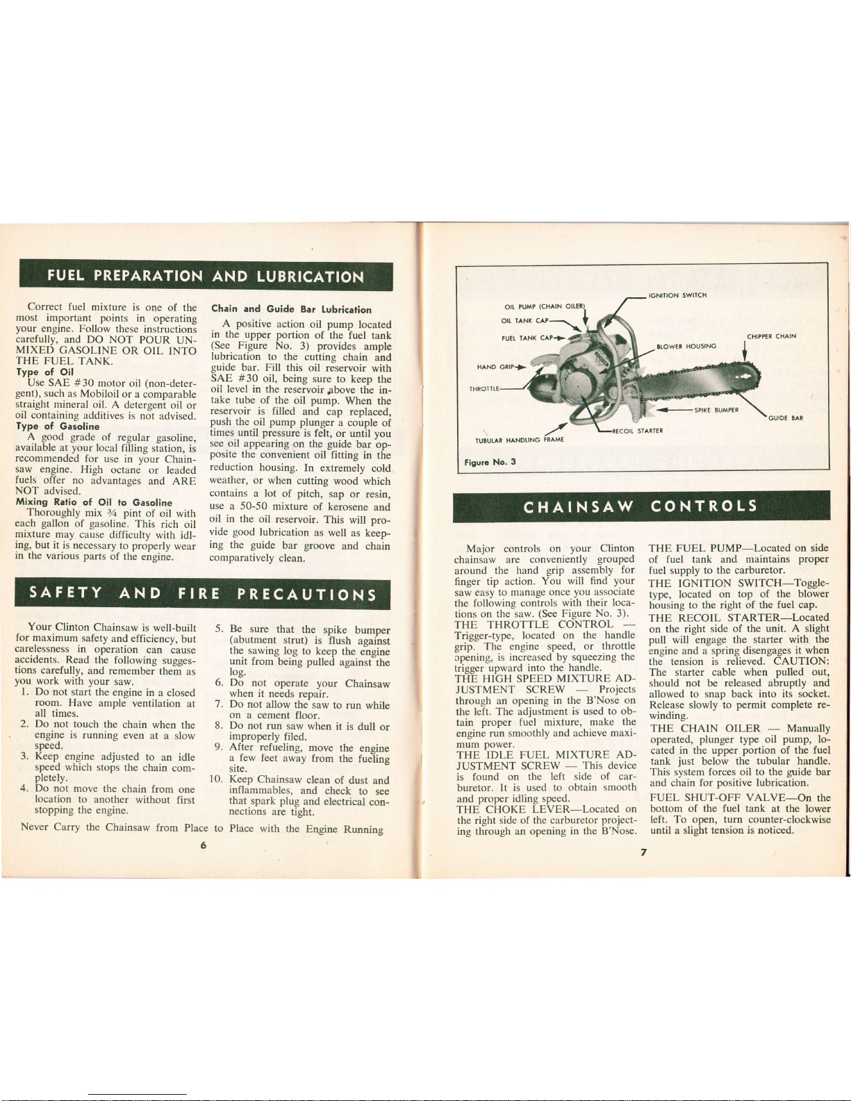
Major
controls
on
your
Clinton
chainsaw
are
conveniently
grouped
around
the
hand
grip assembly
for
finger
tip action.
You will
flnd
Your
saw
easy
to manage
once
you associate
the following controls
with
their loca-
tions on
the saw.
(See
Figure
No. 3).
THE THROTTLE
CONTROL
Trigger-type,
located on
the
handle
grip. The engine
speed,
or throttle
cpening,
is
increased by squeezing
the
trigger
upward into the handle.
THE
HIGH
SPEED
MIXTURE
AD-
JUSTMENT SCREW
Projects
through
an opening
in the B'Nose
on
the left.
The adjustment
is used to
ob-
tain
proper
fuel
mixture,
make the
engine
run
smoothly
and achieve
maxi-
mum
power.
THE IDLE
FUEL
MIXTURE AD-
JUSTMENT
SCREW
-
This device
is found
on the left
side of car-
buretor.
It is
used to obtain
smooth
and
proper
idling
speed.
THE CHOKE
LEVER-Located
on
the right side of
the carburetor
project-
ing through an
opening in
the B'Nose.
THE FUEL PUMP-Located
on side
of fuel tank
and maintains
proper
fuel supply
to the carburetor.
THE IGNITION
SWITCH-Toggle-
type,
located on
top of
the
blower
housing
to the
right of the
fuel
cap.
THE
RECOIL STARTER-Located
on the right
side of the
unit. A slight
pull will engage
the starter with
the
engine
and a spring
disengages
it when
the tension
is relieved. CAUTION:
The starter cable when
pulled
out,
should
not be released abruptly
and
allowed
to snap back into
its socket.
Release
slowly to
permit
complete re-
winding.
THE CHAIN OILER
-
Manually
operated,
plunger
type oil
pump,
lo-
cated
in
the upper
portion
of the fuel
tank
just
below
the tubular
handle.
This system forces
oil to the
guide
bar
and chain
for
positive
lubrication.
FUEL
SHUT-OFF
VALVE-On
the
bottom
of the fuel tank
at the
lower
left. To open,
turn
counter-clockwise
until a slight tension
is
noticed.
6.
7.
8.
9.
10.
IGNITION SWITCH
OII.
PUMP
(CHAIN
OII,
TANK C^P-\
FUEI
IANK
CAP+
CHIPPER
CHAIN
Er.OwtR
HOUSING
GUIDE
SAR
,/
TUEUIAR
HANDI,ING
FRAME
Figurc
No.
3
to
Place with
the
Engine
Running
FUEL
PREPARATION
AND
LUBRICATION
CHAINSAW
CONTROLS
SAFETY
AND
FIRE
PRECAUTIONS
In
order
to
obtain
maximum
effici_
ency
and service
from
your
Chainsaw,
it is
necessary
that
the
engine
be oper-
ated
during
a
break-in
period
of
ap-
proximately
five
(5)
hours.
Never
operate
the
engine
without
load
or
allow
it
to
become
overheated.
proper
breaking
in
of
key parts
will
have
1
Fill
fuel
and
oil
tanks
according
to
Fuel
Preparation
Instructions
on
Page
6.
2.
Open
fuel
tank.
Shut-off
valve.
3.
Open
high
speed
adjustment
screw
lVq
to
lVz
trtrns.
4.
Push
choke
lever
into
.,Choke',
po_
sition.
5.
Turn
ignition
switch
to
,.On.',
6.
Pull
on
recoil
starter
handle,
then
let
it
slowly
return
to
the
socket.
7 .
After
two
or
three
pulls,
engine
will
start.
Then
return
..choke,'
lever
to
"run"
position.
8.
Before
cutting
with
saw,
pump
the
chain
oiler
(See
Figure
No.
3)
a
few
times
to
lubricate
grooye
in
guide
bar.
Use
the pump
frequently
while
the
chain
is
in
operatron.
9.
Run
the
engine
for
a few
minutes
much
to
do
with
the
life
of
your
en_
gine.
Be
sure
to
check
often
for
loose
nuts
and
screws
and
make
all
neces_
sary
adjustments.
Periodic
inspection
and
service
by
your
Authorized
Clin-
ton
Service
Station
dealer
will
result
in
long
life
and good
pdrformance
of
your
Chainsaw.
POWER
RANGE ADJUSTMENTS
1. Start engine and
allow
it to run at
Vz
throttle for a few minutes until
the engine
acquires
uniform tem-
perature.
Never race the engine
when not
under load.
2.
Put the saw in cut, under load and
while cutting check to
see
if engine
backfires.
If
it does,
speed
mixture
is
too lean.
TO CORRECT: Slowly
turn high
speed
mixture needle
valve counter-
clockwise until
the engine runs
smoothly.
(Refer
to
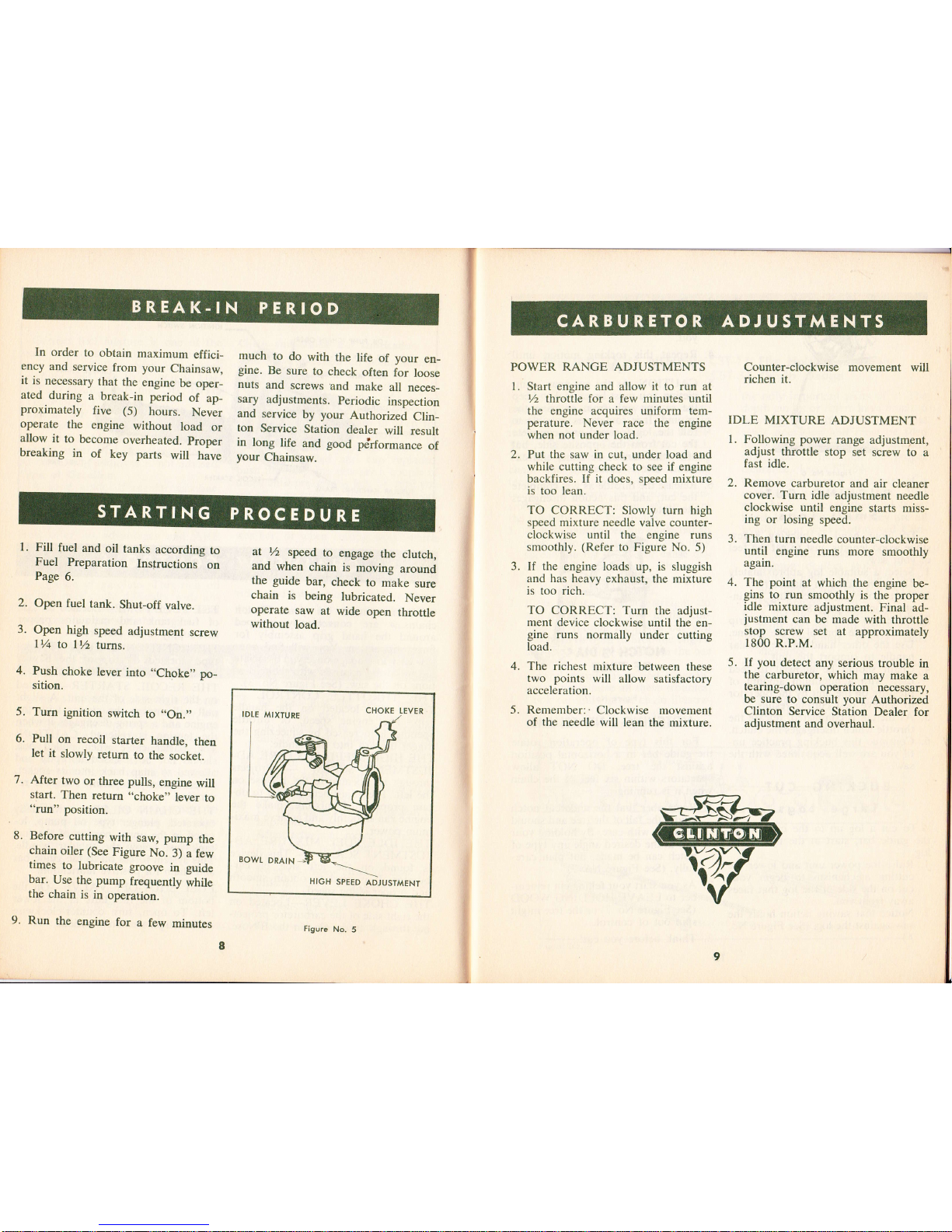
Figure No. 5)
If the engine loads up, is
sluggish
and
has
heavy exhaust, the
mixture
is
too rich.
TO CORRECT:
Turn the
adjust-
ment device
clockwise until the
en-
gine
runs normally under
cutting
load.
The richest
mixture
between these
two points
will
allow
satisfactory
acceleration.
Remember:'
Clockwise
movement
of
the
needle
will lean the mixture.
Counter-clockwise movement
will
richen it.
IDLE
MIXTURE
ADJUSTMENT
1
Following power
range
adjustment,
adjust throttle
stop
set screw to
a
fast idle.
Remove
carburetor
and
air cleaner
cover. Turn idle
adjustment
needle
clockwise
until engine
starts miss-
ing or
losing
speed.
Then
turn needle
counter-clockwise
until
engine
runs
more
smoothly
agaln.
The
point
at which
the engine
be-
gins
to run
smoothly
is the
proper
idle
mixture
adjustment.
Final ad-
justment
can be
made with
throttle
stop
screw
set
at
approximately
1800
R.P.M.
If
you
detect
any serious
trouble
in
the
carburetor,
which
may
make
a
tearing-down
operation
necessary,
be sure to
consult
your
Authorized
Clinton
Service
Station Dealer
for
adjustment
and
overhaul.
2.
at
Yz
speed
to
engage
the
clutch,
and
when
chain
is
moving
around
the guide
bar,
check
to
make
sure
chain
is
being
lubricated.
Never
operate
saw
at
wide
open
throttle
without
load.
3.
4.
J.
4.
5.
5.
CHOKE
TEVER
SPEED
ADJUST
HIGH
'MENT
Figure
No,
5
CARBURETOR ADJUSTMENTS
8
9
 Loading...