

Clint CHA 182-P-604-P, CHA 201-P-702-P, CHA 182-604, CHA 201-702, CHA/K 182-524 Installation, Use And Manteinance Manual
...
ITALIANO / ENGLISH
MANUALE DI
INSTALLAZIONE
USO E
MANUTENZIONE
INSTALLATION,
USE AND
MANTEINANCE
MANUAL
Emissione / Issue
Sostituisce / Replaces
Manuale / Manual
05.08
CLM 61 ab
09.05
CHA 182-P÷604-P
CHA 182÷604
CHA 201-P÷702-P
CHA 201÷702
CHA/K 182÷524
CHA/K 182-P÷604-P
CHA/Y 221÷802
CHA/Y 2821÷604
Serie / Series
2
CHA - CHA/K
0. ELENCO DOCUMENTI ALLEGATI
Elenco documentazione fornita a corredo della macchina
facente parte integrante del presente manuale.
- Quaderno tecnico
- Manuale microprocessore
- Certificato di garanzia
- Dichiarazione di conformità
- Schemi elettrici specifici
0. LIST OF ATTACHMENTS
List of documents supplied with the unit and forming an
integral part of this manual.
- Technical book
- Microprocessor manual
- Certificate of guarantee
- Declaration of conformity
- Specific electrical circuit

3
CHA - CHA/K
INDICE CONTENTS
Argomento
ELENCO DOCUMENTI ALLEGATI
PREMESSA
Informazioni generali
Allegati
Avvertenze
DESCRIZIONE DELLA MACCHINA
Identificazione
Identificazione della macchina
Destinazione d'uso
Controindicazioni
Descrizione generale
SICUREZZA
Definizioni
Regole generali di sicurezza
Simbologia
Mappa dei segnali di sicurezza
Segnali di sicurezza
Dispositivi di emergenza e di sicurezza
Descrizione del rischio residuo
Rischio residuo in prossimità della macchina
Misure da adottare in caso di fuoriuscita di
gas frigorigeno
Operazioni con rimozione dei pannelli
ISPEZIONE, TRASPORTO
Ispezione
Stoccaggio
Sollevamento e trasporto
Disimballo
INSTALLAZIONE
Scelta del luogo di installazione
Collegamento idraulico
Generalità
Evaporatore
Subject
LIST OF ATTACHMENTS
INTRODUCTION
General information
Attachments
Warnings
UNIT DESCRIPTION
Identification
Identification
Intended use
Contraindications
General description
SAFETY
Definition
General safety regulations
Symbols
Location of safety signs
Safety signs
Emergency and safety devices
Description of residue risks
Residue risks near the unit
Measures to take in case of leaking refrigerant gas
Operations with the panels removed
INSPECTION AND TRANSPORT
Inspection
Storage
Lifting and transport
Unpacking
INSTALLATION
Choosing the installation site
Water connections
General
Evaporator
0
1
1.1
1.2
1.3
2
2.1
2.1.1
2.2
2.3
2.4
3
3.1
3.2
3.3
3.3.1
3.3.2
3.4
3.5
3.5.1
3.5.2
3.5.3
4
4.1
4.2
4.3
4.4
5
5.1
5.2
5.2.1
5.2.2
0
1
1.1
1.2
1.3
2
2.1
2.1.1
2.2
2.3
2.4
3
3.1
3.2
3.3
3.3.1
3.3.2
3.4
3.5
3.5.1
3.5.2
3.5.3
4
4.1
4.2
4.3
4.4
5
5.1
5.2
5.2.1
5.2.2

4
CHA - CHA/K
Collegamenti elettrici
Generalità
Collegamento elettrico del flussostato/
pressostato differenziale
Collegamento elettrico della pompa di circolazione
Consensi esterni
AVVIAMENTO
Controlli preliminari all'avviamento
Messa in funzione
Verifiche durante il funzionamento
Generalità
Sbrinamento
(Solo unità pompa di calore)
Arresto del gruppo
FUNZIONAMENTO
Generalità
Fermata stagionale
RICERCA GUASTI
MANUTENZIONE E CONTROLLI PERIODICI
Avvertenze
Generalità
Controlli mensili
Controlli quadrimestrali
Riparazioni del circuito frigo
Rabbocchi di refrigerante
DISMISSIONE E SMALTIMENTO
5.3
5.3.1
5.3.2
5.3.3
5.3.4
6
6.1
6.2
6.3
6.3.1
6.3.2
6.4
7
7.1
7.2
8
9
9.1
9.1.1
9.1.2
9.2
9.3
10
Electrical connections
General
Electrical connections to the flow switch/
differential water pressure switch
Electrical connections to the circulation pump
External signals
START UP
Preliminary controls
Start up
Checks during unit operation
General
Defrosting
(Only heat pump units)
Stopping the unit
OPERATION
General
Seasonal shut down
TROUBLE SHOOTING
ROUTINE MAINTENANCE AND CONTROLS
Warnings
General
Monthly controls
Four-monthly controls
Repairing the refrigerant circuit
Topping up the refrigerant liquid
SHUT DOWN AND DISPOSAL
5.3
5.3.1
5.3.2
5.3.3
5.3.4
6
6.1
6.2
6.3
6.3.1
6.3.2
6.4
7
7.1
7.2
8
9
9.1
9.1.1
9.1.2
9.2
9.3
10
5
CHA - CHA/K
1. PREMESSA
1.1 INFORMAZIONI GENERALI
Questo manuale contiene le norme di installazione,
uso e manutenzione dei refrigeratori CHA - CHA/K,
evidenziandone rischi e pericoli connessi. Esso è stato
espressamente studiato e sviluppato per permettere
al personale preposto un utilizzo facile e in sicurezza
dei refrigeratori d’acqua CHA - CHA/K. Leggere attentamente e completamente tutte le informazioni in esso
riportate. Prestare particolare attenzione alle norme
evidenziate con
in quanto se non osservate possono causare danno alle
persone, all’ambiente e/o alla macchina stessa.
La società declina ogni responsabilità per qualsiasi uso
improprio della macchina, per modifiche alla stessa non
autorizzate o per la non osservanza delle norme riportate
sul manuale.
Il manuale deve essere conservato il luogo sicuro e messo
a disposizione del personale addetto alla conduzione ed
alla manutenzione del refrigeratore.
1.2 ALLEGATI
Fanno parte integrale del presente manuale i documenti
evidenziati a pag. 2.
1.3 AVVERTENZE
Le unità CHA - CHA/K sono state progettate e costruite
per garantire nel tempo grande affidabilità di esercizio
e massima sicurezza; per questo e grazie alle scelte
progettuali e realizzative, la società può garantire la
totale conformità agli standard di sicurezza CE.
Ulteriore garanzia è assicurata dai collaudi cui la macchina è stata sottoposta in fabbrica.
All’utente resta quindi soltanto l’impegno di un uso proprio e di una manutenzione preventiva conforme alle
indicazioni contenute in questo manuale.
Ogni intervento, di qualsiasi natura, sulla
macchina deve essere preceduto da una
attenta lettura del presente manuale in tutte le sue parti.
1. INTRODUCTION
1.1 GENERAL INFORMATION
This manual contains the installation, use and maintenance instructions for the CHA - CHA/K chillers, andCHA - CHA/K chillers, and chillers, and
highlights all connected risks and perils. It has been
expressly prepared and written to allow authorised users to use the CHA - CHA/K water chillers in completeCHA - CHA/K water chillers in complete water chillers in complete
safety and with the greatest of ease. Please read the
whole of this manual with care, paying special attention
to the sections marked with
as non-compliance may cause harm to people, deteriorate
the environment and/or damage the unit.
The company declines all responsibility for any improper
use of the unit, unauthorised modifications or non-compliance with the instructions contained in this manual.
Please keep this manual in a safe place and make it
available to chiller operators and maintenance men.
1.2 ATTACHMENTS
The documents shown on page 2 form an integral part
of this manual.
1.3 WARNINGS
The CHA - CHA/K units have been designed and builtCHA - CHA/K units have been designed and built units have been designed and built
to ensure long-term operating reliability and maximum
safety; for this reason and thanks to the company’s
design and construction policy, the company is able
to guarantee that this product totally complies with EC
safety standards.
A further guarantee of this is provided by the factory
tests carried out on the unit.
The user, therefore, must only ensure the unit is properly
used and that maintenance operations are carried out
according to the indications contained in this manual.
The unit should not be touched until the whole
of this manual has been carefully read.
6
CHA - CHA/K
Il manuale di installazione, uso e manutenzione deve essere sempre a disposizione degli addetti, i quali, prima di ogni operazione
sulla macchina, devono obbligatoriamente
leggerlo.
Per ogni ulteriore informazione e chiarimento la
G.I. HOLDING S.p.A. si rende disponibile al seguente
indirizzo:
G.I. HOLDING S.p.A.
Assistenza Clienti
Via Max Piccini, 11/13 - 33050 RIVIGNANO (UD)
ITALY
tel. +39 0432 773220
fax +39 0432 773855
e-mail: info@clint.it
This installation, use and maintenance manual must always be kept within easy reach
of authorised staff who are obliged to read
it before carrying out any operations on the
unit.
For any further information or explanations please contact
G.I. HOLDING S.p.A. at the following address:
G.I. HOLDING S.p.A.
Customer Service
Via Max Piccini, 11/13 - 33050 RIVIGNANO (UD)
ITALY
tel. +39 0432 773220
fax +39 0432 773855
e-mail: info@clint.it
7
CHA - CHA/K
2 DESCRIZIONE DELLA MACCHINA
Questo capitolo ha lo scopo di fornire una descrizione
generale delle caratteristiche principali della macchina
nel suo insieme, unitamente a quella dei principali componenti, standard e opzionali.
2.1 IDENTIFICAZIONE
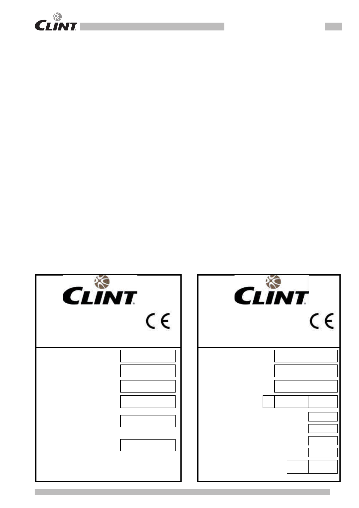
2.1.1 Identificazione della macchina
La macchina si identifica tramite le targhette poste sul
telaio e sul quadro elettrico. Le targhette riportano i
seguenti dati:
- Ragione sociale dell'Azienda
- Indirizzo dell'Azienda
- Designazione della serie e del tipo di unità
- Numero di matricola
- Anno di costruzione
- Tipo e quantità di refrigerante
- Massima pressione ammissibile
- Taratura dei pressostati
- Simbolo della certificazione CE
- Caratteristiche elettriche
- Identificazione schema elettrico
2 UNIT DESCRIPTION
This chapter contains a general description of the main
unit characteristics, together with those of its principal
standard and optional components.
2.1 IDENTIFICATION
2.1.1 Unit identification
The unit can be identified throug the plats attached on
the frame and in the electrical box. This label contains
the following information:
- Manufacturer’s name
- Manufacturer’s address
- Description of the series and type of unit
- Series number
- Year of construction
- Type and quantity of refrigerant liquid
- Max. Allowable pressure
- Pressure switch set point
- EC certification symbol
- Electrical characteristics
- Wiring diagram identification
G.I. HOLDING S.p.A
G.I. HOLDING S.p.A
Via Max Piccini 11/13
Via Max Piccini 11/13
33050 Rivignano
(UD)
33050 Rivignano
(UD)
ITALIA
ITALIA
Tel. +39 0432 773220
Tel. +39 0432 773220
Fax. +39 0432 773855
Fax. +39 0432 773855
E-mail: info@clint.it
E-mail: info@clint.it
Web: www.clint.it
Web: www.clint.it
Manufactured by BV ITA 40,02,1023
Modello
Modello
Model
Model
Matricola
Matricola
Serial number
Serial number
Alimentazione di Potenza
Anno di costruzione
Main Power
Construction year
Corrente massima assorbita
Refrigerante
Max absorbed current
Refrigerant
ALTA
HIGHT PRESSURE
BASSA
LOW PRESSURE
ALTA
HIGHT PRESSURE
BASSA
LOW PRESSURE
Olio
1/2
2/2
Potere nominale di chiusura in cortocircuito
Rated short circuit making capacity
(PS) Max. Press. Ammissibile
kA
0062
V/Hz/Ph
A Gr.2
Kg
Oil
Schema elettrico n°
Wiring diagram Nr.
Max. Allowable pressure (PS)
bar
bar
s
bar
bar
bar
8
CHA - CHA/K
2.2 DESTINAZIONE D’USO
I CHA - CHA/K sono refrigeratori con condensazione
ad aria destinati a raffreddare acqua (eventualmente
addizionata con glicole etilenico inibito) che circola in
un anello chiuso. Le unità a pompa di calore possono,
a seconda del ciclo di funzionamento scelto, raffreddare
o riscaldare l’acqua dell’anello.
Le unità a recupero di calore , possono, come sottoprodotto, riscaldare dell’acqua che circola in un secondo
anello chiuso.
Il caldo, o il freddo, così prodotto può essere utilizzato per
impianti di climatizzazione o per processi industriali.
2.3 CONTROINDICAZIONI
Non impiegare in prossimità della macchina
prodotti infiammabili.
Non impiegare in prossimità della macchina sostanze in grado di formare miscele
esplosive.
Non impiegare la macchina dove sussistono
problemi di impatto ambientale (vedi punto
3.5 pag. 13).
2.4 DESCRIZIONE GENERALE
Tutte le strutture sono realizzate in lamiera zincata con
ulteriore protezione ottenuta tramite verniciatura a polveri
poliestere. La struttura è autoportante ed i pannelli sono
facilmente rimovibili in modo da permettere l’accesso
all’interno della unità per le operazioni di manutenzione
e riparazione.
Gli schemi funzionali e la componentistica usata sono
allegati.
2.2 INTENDED USE
The CHA - CHA/K series of air condensation chillers
have been designed to cool water (possibly containing
inhibited ethylene glycol) circulating in a closed circuit.
The heat pump units can cool or heat the water in the
closed circuit depending on which operating cycle is
chosen.
The heat recovery units can also heat the water circulating in a second closed circuit.
The heat or cold produced can be used for air-conditioning
systems or industrial processes.
2.3 CONTRAINDICATIONS
Do not use inflammable products near the
unit.
Do not use substances that can form explosive mixtures near the unit.
Do not use the unit in conditions that could
be harmful for the environment (see point
3.5 on page 13).
2.4 GENERAL DESCRIPTION
All the unit structures are made from galvanised sheet
metal and are further protected with polyester powder
paints. The structure is free standing and the panels are
easy to remove in order to allow access to the inside of
the unit for maintenance and repair operations.
The functional diagrams and the components used are
attached to this manual.
9
CHA - CHA/K
3 SICUREZZA
3.1 DEFINIZIONI
In questo documento verranno utilizzate le seguenti
definizioni:
- Zone pericolose: qualsiasi zona all’interno e/o in
prossimità della macchina in cui la presenza di una
persona esposta costituisca un rischio per la sicurezza
e la salute di detta persona.
- Persona esposta: qualsiasi persona che si trovi inter-
namente o in parte in una zona pericolosa.
- Operatore/Manutentore: la o le persone incaricate di
far funzionare, regolare, eseguire la manutenzione,
riparare, movimentare la macchina.
3.2 REGOLE GENERALI DI SICUREZZA
È vietato alle persone non autorizzate avvicinarsi alla macchina.
Prima di ogni intervento di manutenzione
sulla macchina, seguire scrupolosamente
quanto indicato nel capitolo 9 a pag. 30.
È vietato l’ingresso all’interno della macchina. L’accesso è consentito solo al personale
qualificato e solo a macchina ferma.
È vietata la rimozione delle protezioni e
l’esclusione dei dispositivi di sicurezze e
di emergenza.
È vietato stazionare sulla macchina.
- Impiegare la macchina solo per l’uso a cui essa è
destinata.
- Il costruttore non risponde dei danni derivanti da un
impiego improprio della macchina o da modifiche
tecniche effettuate sulla macchina.
- Controllare regolarmente se i dispositivi di sicurezza
presentano un funzionamento corretto.
- Non smontare, modificare o mettere fuori funzione
parti della macchina.
- Per tutti gli interventi da effettuare sulla macchina,
utilizzare esclusivamente attrezzi ed equipaggiamenti
idonei e in buone condizioni. Gli operatori dovranno
indossare i normali dispositivi di protezione individuali
(guanti, casco, occhiali, ecc.).
3 SAFETY
3.1 DEFINITION
This document uses the following definitions:
- Dangerous areas: any area inside and/or near to the
unit in which the presence of a person would give rise
to a risk for that person’s health.
- Exposed person: anyone who is wholly or partly inside
a dangerous area.
- Operator/Maintenance man: person or persons autho-
rised to operate, adjust, service, repair or move the
unit.
3.2 GENERAL SAFETY REGULATIONS
It is forbidden for unauthorised persons to
approach the unit.
Scrupulously observe the contents of Chapter 9 on page 30 before carrying out each
maintenance operation on the unit.
It is forbidden to enter the unit. Access is
only permitted to qualified staff when the
unit is disconnected.
It is forbidden to remove safety guards and
by-pass safety and emergency devices.
It is forbidden to stand on the unit.
- Only use the unit to do what it was built for.
- The manufacturer declines all responsibility for damage
deriving from improper use or technical modifications
made to the unit.
- Check the safety devices are in perfect working order
on a regular basis.
- Do not dismount, modify or disconnect unit parts.
- When working on the unit, only use suitable tools and
equipment in good condition. Operators must wear
normal personal protection equipment (gloves, helmet,
goggles, etc.).
10
CHA - CHA/K
- I lavori sull’equipaggiamento elettrico devono essere
eseguiti solo da un elettricista qualificato.
- Gli interventi sul circuito frigorifero possono essere
effettuati solo da personale specializzato.
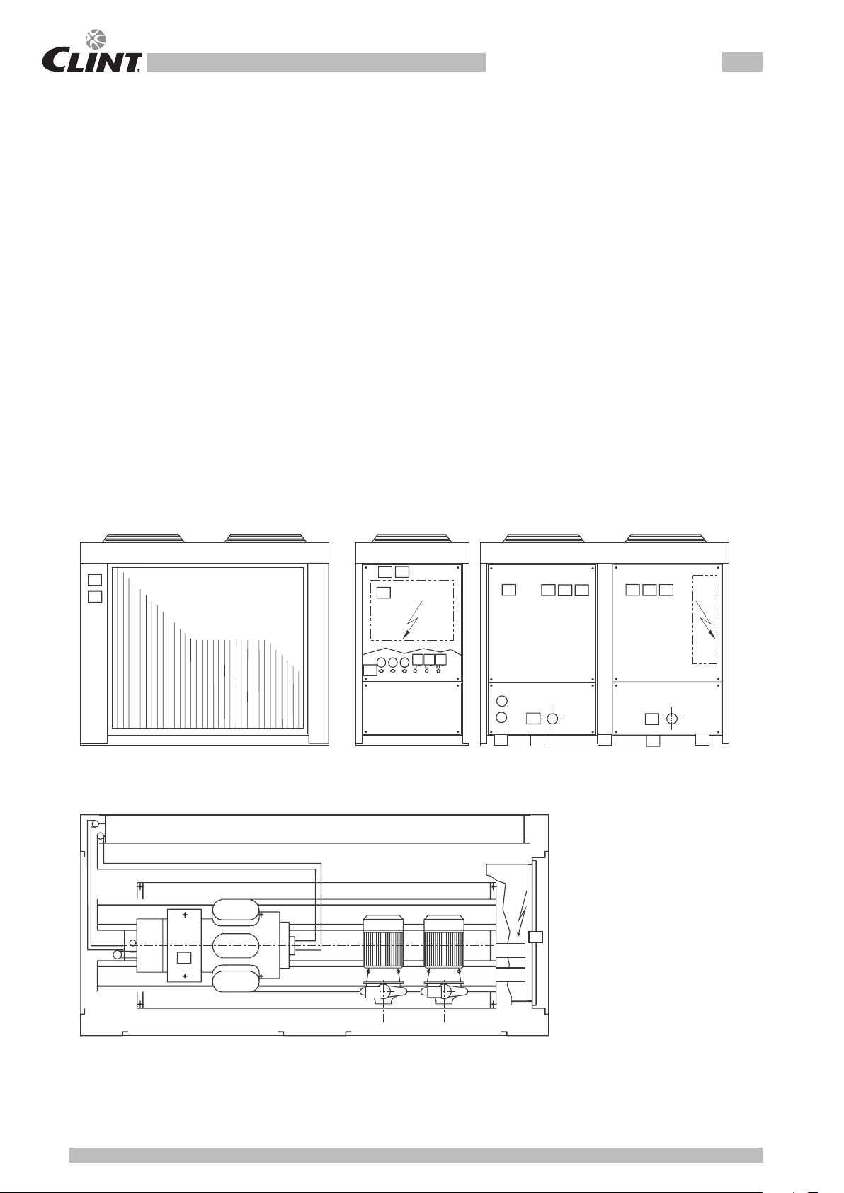
3.3 SIMBOLOGIA
Verificare periodicamente lo stato delle targhette e provvedere, in caso di necessità, al loro ripristino.
3.3.1 Mappa dei segnali di sicurezza
- Work on the electrical system of the unit may only be
carried out by a qualified electrician.
- Work on the refrigerant circuit may only be carried out
by specialised staff.
3.3 SYMBOLS
Check the state of the plates on a regular basis and
repair them if necessary.
3.3.1 Location of safety signs
1
15
2
7
10
16
9
13114
15
4
13
14
15
5
11
12
11
12
11
3
6
6
8
 Loading...