

Climma CWS BASIC 121, CWS BASIC 201, CWS BASIC 161, CWS BASIC 251, CWS 121RC Installation, Operation And Maintenance Manual
...
CWS Basic 121-161-201-251
www.climma.it
CHILLER SYSTEM
MODELS CWS BASIC
121-161-201-251
INSTALLATION, OPERATION AND
MAINTENANCE MANUAL
S.p.A.
COMPANY
WITH QUALITY SYSTEM
CERTIFIED BY DNV
ISO 9001/2000
Via Cantore, 6/8 - 20034 Giussano (MI) ITALY
Tel. +39 0362.35321 - fax +39 0362.852995
info@veco.netE-mail:
Cod. A041250 01/09/06

Page 1
1- ELECTRICAL CONNECTIONS
CWS Basic 121-161-201-251
All the connections must be made by skilled technical engineers
and must comply with the safety rules of the country where the unit
is installed.
The unit must be connected to a good ground connection, using a
cable of correct size.
Supply must be made using a cable adequate to the maximum
operating load. Also the sea-water pump line should be done with a
cable adequate to the power.
Supply must be connected from a suitable circuit breaker. Any
maintenance or inspection to the system must be performed disconnecting first the mains supply.
1.1- Mains supply
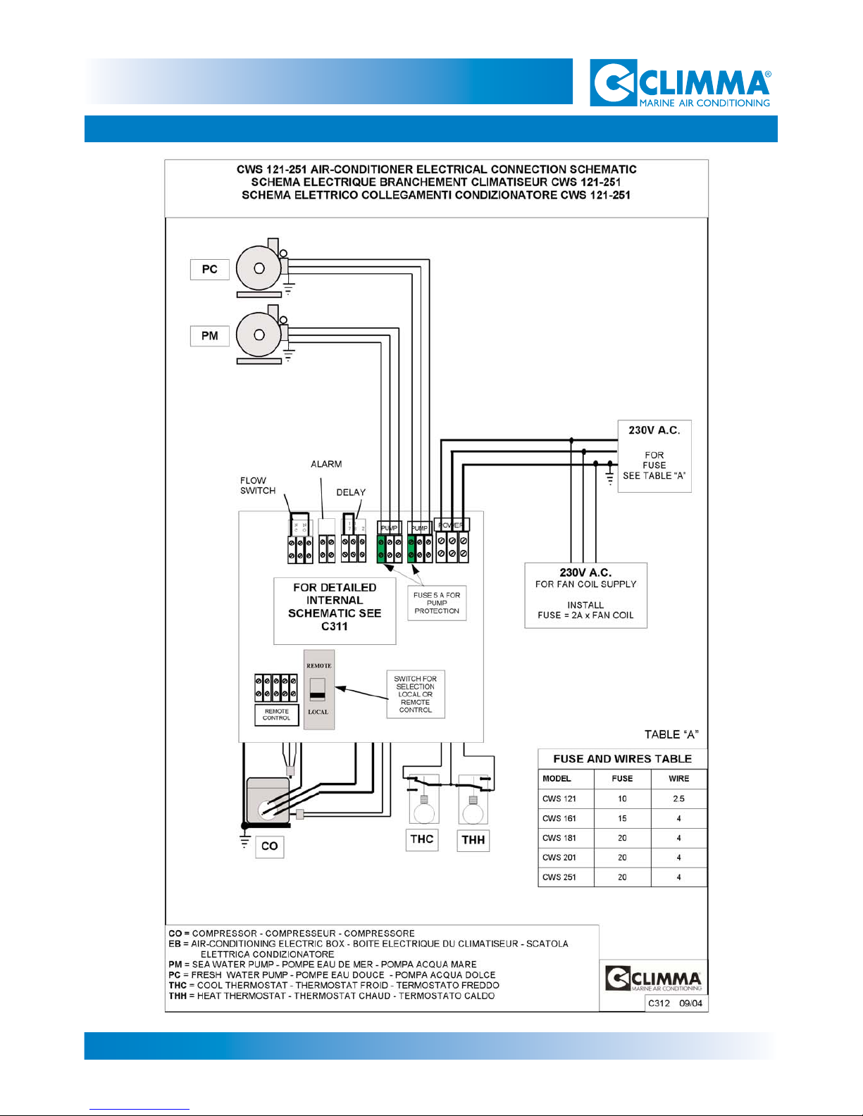
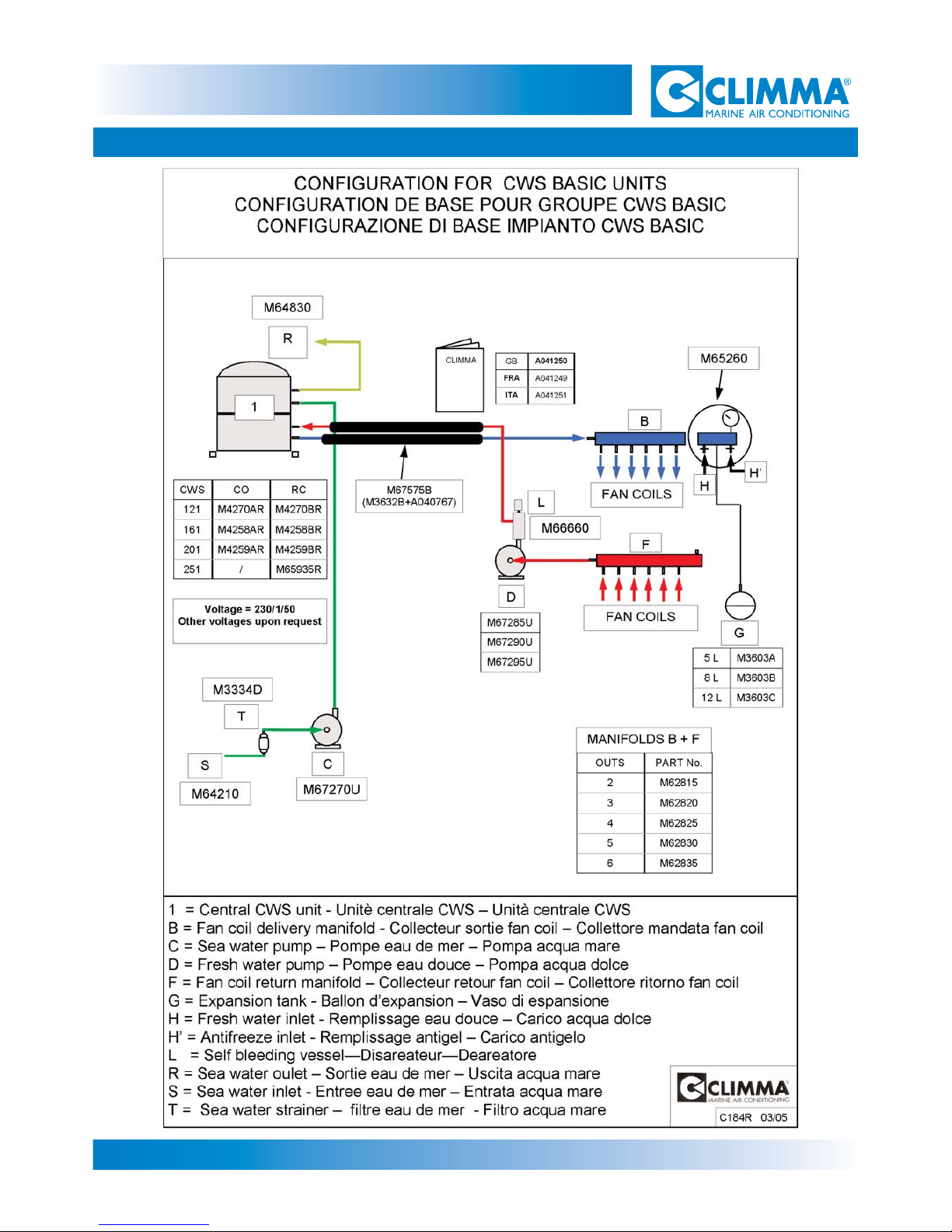
The connections of the other system components must be made following our
schematics C312 (p.2) and C650 for the triphase version (p.3).
Both pumps connections are equipped with internal fuse (5A).
1.2- Connection of the system components
Page 2
1- ELECTRICAL CONNECTIONS
CWS Basic 121-161-201-251

Page 3
1- ELECTRICAL CONNECTIONS
CWS Basic 121-161-201-251
C650 02/02
CWS 251 RY AIR-CONDITIONER ELECTRICAL CONNECTION SCHEMATIC
SCHEMA ELECTRIQUE BRANCHEMENT CLIMATISEUR CWS 121 - 251 RY
SCHEMA ELETTRICO COLLEGAMENTI CONDIZIONATORE CWS 121 - 251 RY
PM
CO = COMPRESSOR - COMPRESSEUR - COMPRESSORE
EB = AIR-CONDITIO NING ELECTRIC BOX - BOITE ELECTRIQUE DU CLIMATISE UR - SCATOLA
EL ET TRICA COND I ZI ONATORE
PM = SEA WATER PUMP - POMPE EAU DE MER - POMPA ACQUA MARE
PC = FRESH WATER PUMP - POMPE EAU DOUCE - POMPA ACQUA DOLCE
THC = COOL THERMOSTAT - THERMOSTAT FROID - TERMOSTATO FREDDO
THH = HEAT THERMOSTAT - THERMOSTAT CHAUD - TERMOSTATO CALDO
230V A.C.
FOR FAN COIL SUPPLY
INSTALL
FUSE = 2A x FAN COIL
PC
CO
THC
THH
EB
FLOW
SWITCH
EXTERNAL
CONTROL
ALARM
DELAY
PUMP
PUMP
FUSE 5 A FOR
PUMP
PROTECTION
Supply
400V
A.C.
S
POWER
1 1 A
7 8 2
N N C
C O
T R N
GND S R N GND
T
POWER
La scatola elettrica contiene un dispositivo di
sicurezza per impedire al compressore di
girare nella direzione sbagliata. Quindi, dopo
av er colleg ato l’a l i mentazione, se il
compressore non dovesse avviarsi invertire
sui morsetti la fase S con la T come mostrat o
sopra.
The electric box has a motor protector inside
to avoid compressor spinning in the wrong
way. If, after supply connection, the
compressor doesn’t work, invert phase S with
ph ase T on t erminal b ase (as shown in the
scheme above
ATTENZIONE-ATTENTION
Electric Box
Cod. M66765R Y
Page 4
2- SEA WATER CIRCUIT
CWS Basic 121-161-201-251
2.1 - Sea-water pump
The sea-water pump is needed to circulate the given water quantity through
the refrigerant sea-water exchanger. The sea-water pump should also be
quiet, continous duty rated, of marine grade construction material.
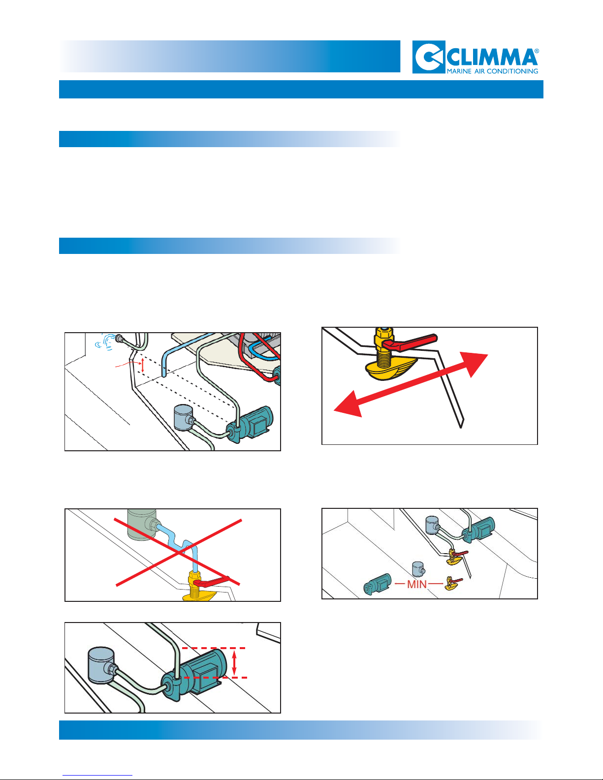
2.2 - Location
BOW
STERN
25 cm
A - The pump should be installed with the shaft in
horizontal position and the water outlet at top. The
centrifugal pump must be installed at least 0,50 m
below the water line.
B - The water intake must be "scoop" type, oriented
forward.
C - Seacock, strainer and pump intake should be
connected without siphoning; the piping should
always rise from seacock to the pump.
D - The intake line should be as short as possible (it
is very difficult to run a good circuit with an intake
piping longer than 1 m).
E - The outlet line of the pump should rise at least
for 25 cm (10 in.) just after the pump outlet in order
to keep the pump primed at all times.
0,5 m
Page 5
2- SEA WATER CIRCUIT
CWS Basic 121-161-201-251
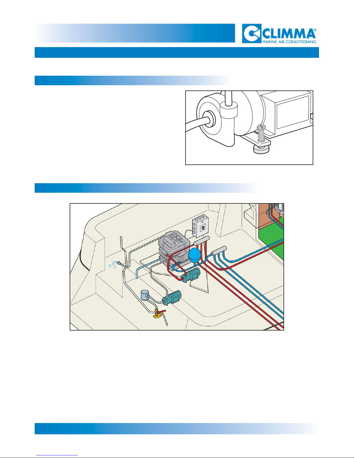
The pump should be fastened with adequate
screws using the holes in its base or the special
fixing base (available for small models). For larger pumps, the original quiet and smooth running can be improved by using a silent block
mounting.
2.3 - Installation
2.4- Sea-water circuit
Some rules are given at chapter 2.2.
We can resume the following: the circuit should always rise from water intake to the unit
manifold. After that the circuit can rise again or drop to the discharge port. It is absolutely
important to prevent that the circuit rises and drops making siphons, which will prevent air
to be drained, causing an airlock during the navigation. The discharge side of the circuit
should be made so that the water discharge won't cause excessive noise both for this yacht
and its neighbours.
Page 6
3- FRESH WATER CIRCUIT
CWS Basic 121-161-201-251
Follow the installation schematic, with particular regard to the sense and position of components.
Keep in mind the accessibility of components for the following steps of installation and also for
maintenance. Respect the flow sense marked on the unit.
Keep accessible the purging valve installed on the fresh water return. Respect the nominal diame-
ters of the manifold.
Manifold: install it in an accessible position, if possible with a certain heel (purging valve higher).
Check that each calibrating valve (if installed) of the manifold is fully open.
Expansion tank: respect the schematic. Connecting port must be upwards to drain out of it.
Fresh water pump: respect the layout schematic.
Fresh water circuit: keep in mind that the easiest and shortest is the best.
Theorethically any "high" point in the circuit must have a purging valve. Siphoning and "up-anddown" must be avoided as anyway they make the air purging difficult and trap air.
Fan coil: respect the flow sense. Each fan coil is equipped with a purging valve that must be accessible both at installation and also for maintenance.
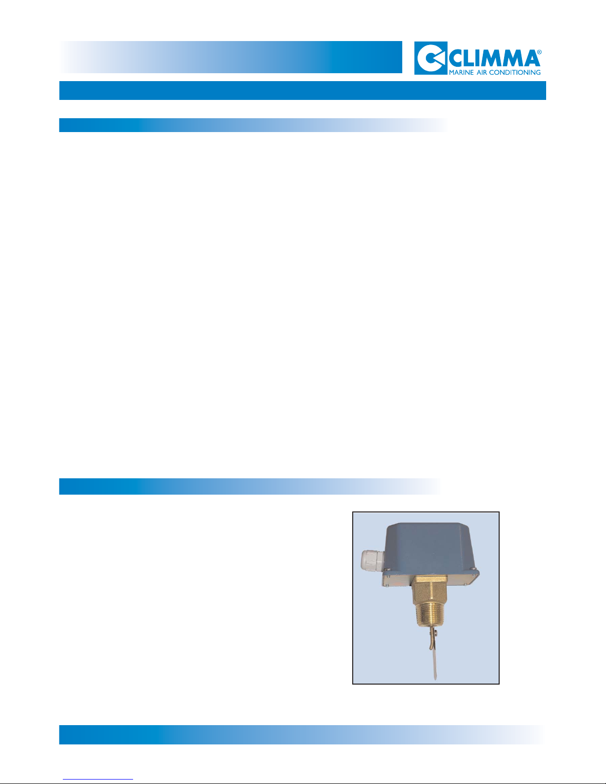
This item must be installed on the fresh water
manifold. It must be accessible for maintenance and calibration.
The flow switch is needed as a safety device
which cuts out the compressor if the fresh
water circulation stops or is not enough.
The flow must be electrically connected to the
electrical box (two wires cables and ground
connection), as specified in the electrical
schematic.
3.1- 1Fresh water circuit connections
3.2- Flow switch (option)

Page 7
3- FRESH WATER CIRCUIT
CWS Basic 121-161-201-251
When the circuit is under pressure with the antifreeze solution, purge the air as follows:
Bleed the entire circuit (manifold, fan coils and all the other purging points) starting from the lowest level
and keeping the circuit pressure at 1,5 Bars.
This purging must be done without running the pump.
Repeat all points, until no more air comes out from the bleeding valves, still keeping the pressure at 1,5
Bars.
Set to "Off" position each compressor switch.
Then check the sea-water intake is open and start the unit in "Cool" mode; both pumps will run.
Let the fresh water pump run for 30 seconds, then stops the system and bleed again all points, keeping
the pressure at 1,5 Bars.
Bleeding can be considered over when no more air is coming off the purging points and the fresh water
circulation pump runs even and quiet.
We strongly recommend that a special "air bleeding vessel" be installed in the fresh water circuit, just after
the pump outlet. This device will dramatically reduce the bleeding procedure and will also keep the system
free of air during its life. The "air bleeding vessel" is available in several sizes.
3.3- Pressurizing the fresh
The gauge set installed in the fresh water circuit is equipped with two charging ports, each (H-H1)
with a manual valve and an automatic check valve, which prevents the internal charge to come back
to the pressurized sanitary circuit in case of mistake. Use one of the two valves to charge and pressurize the circuit with fresh water up to 1,5 Bars, checking it with the pressure gauge. This port must
be permanently connected to the yacht sanitary water system.
Check that the circuit keeps the pressure over a certain period of time indicating that it is leak proof.
As you are sure that the circuit is leak proof, reduce the pressure to make room and add antifreeze
to the circuit.
3.4- Antifreeze solution
We suggest two methods for filling the fresh water circuit with antifreeze:
a) Calculate approximately the circuit capacity, fill it with water and add to it 20% of antifreeze, using
the second charging valve by gravity or using a pressure pump. Then connect the circuit to the sanitary water circuit of the vessel, pressurize up to 1,5 Bars and start purging the air. It is obvious that
if purging will be difficult, the percentage of antifreeze will decrease, as more water will be needed to
fill the circuit, therefore more antifreeze must be added to the circuit.
b) Empty the circuit from the water used for the leak test. Prepare the antifreeze solution in the quantity needed to fill the circuit, made with 20% of antifreeze liquid; fill the circuit, using a pressure pump.
Then proceed with purging air and topping up the pressure using the solution.
water circuit
3.5- Air bleeding
Page 8
3- FRESH WATER CIRCUIT
CWS Basic 121-161-201-251
 Loading...