

Climma COMPACT QUATTRO, SPLIT QUATTRO Installation Manual Use & Schematics
COMPACT & SPLIT - QUATTRO
www.climma.it
AIR-CONDITIONERS
COMPACT end SPLIT modelsQUATTRO
INSTALLATION MANUAL
USE & SCHEMATICS
Cod. A52040 19/03/08
S.p.A.
COMPANY
WITH QUALITY SYSTEM
CERTIFIED BY DNV
ISO 9001/2000
Via Cantore, 6/8 - 20034 Giussano (MI) ITALY
Tel. +39 0362.35321 - fax +39 0362.852995
info@veco.netE-mail:
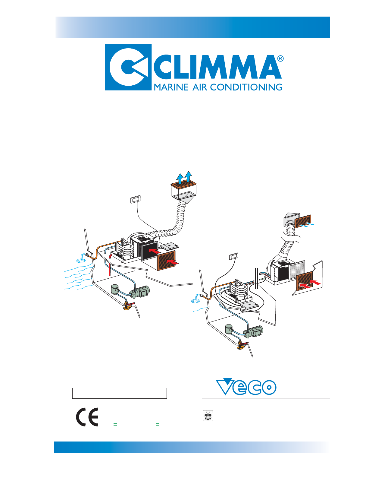
COMPACT
QUATTRO
SPLIT
QUATTRO
18 - marzo - 2008
AIR-CONDITIONERS
COMPACT and SPLIT QUATTRO models
page 2
www.climma.it
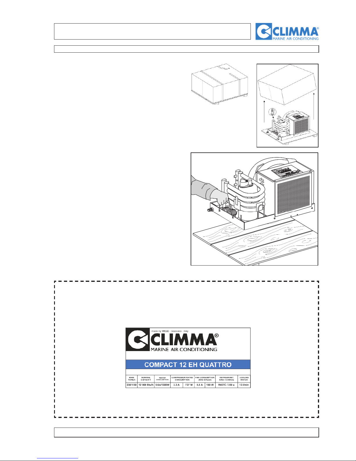
1.1 - CRATING
The CLIMMA air-conditioning unit is fastened to a
wood plane and crated. Pay attention at opening.
Unhook the unit, unscrewing the provided clamps.
Keep them to fasten the unit on the boat.
Raise the unit using the rope handles provided for
this purpose. Don’t raise it getting hold of fans and
pipes, that can suffer damage.
On the unit there is a label that describes its technical specifications.
NOTE
Check that the technical specifications, the electrical supply, etc.... on the label corre-
spond to the technical specifications of the boat.
EXAMPLE OF LABEL
AIR-CONDITIONERS
COMPACT and SPLIT QUATTRO models
page 3
www.climma.it
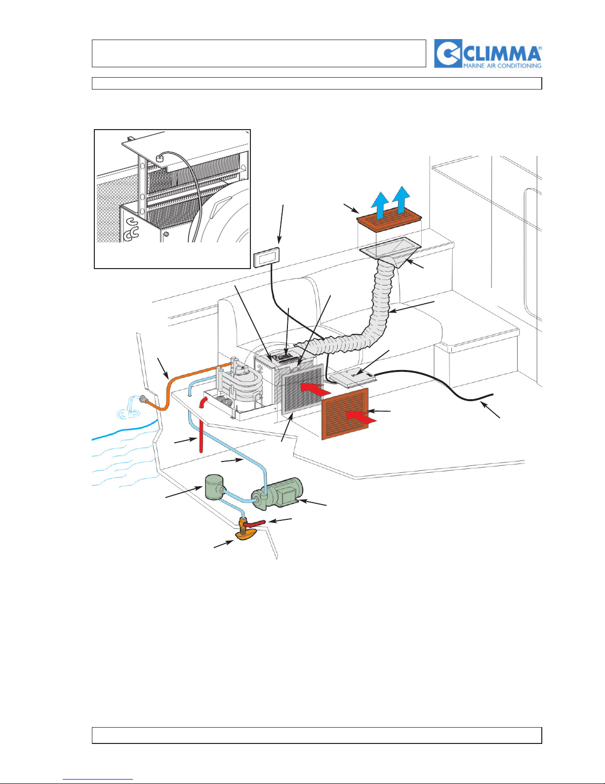
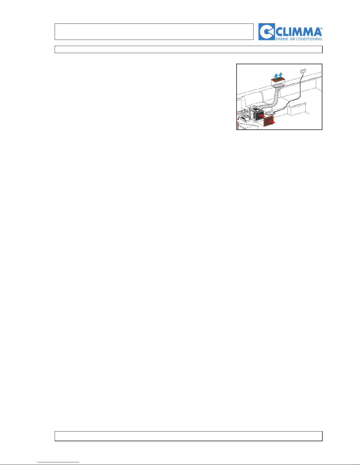
2.1 Installation diagram of the Compact air-conditioner
04) Electrical box
05) Electrical supply
06) Air inlet grill
07) Air filter
08) Remote control panel
09) Insulating flexible duct
10) Air outlet plenum
11) Air outlet grill
12) Condensation drainpipe
13) Sea water inlet pipe
14) Sea water pump
15) Sea water intake valve
16) Sea water filter
17) Sea water intake
18) Thermostat bulb
19) Air-conditioner
20) Sea water drainpipes
08
17
16
15
14
13
12
06
11
10
04
18
09
07
19
20
05
Electrical heating (EH) version.
AIR-CONDITIONERS
COMPACT and SPLIT QUATTRO models
page 4
www.climma.it
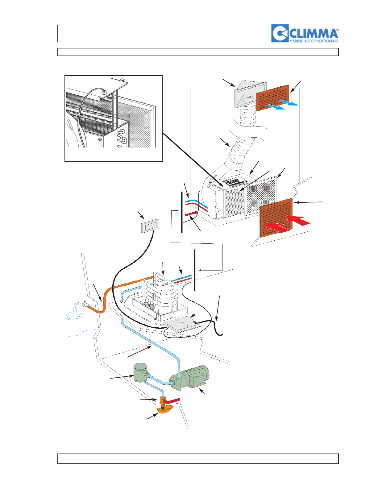
2.2 Installation diagram of the Split air-conditioner with EV
01) EV exchanger
02) Split compressor
03) Connecting pipes for refrigerant
04) Electrical box
05) Electrical supply
06) Air inlet grill
07) Air filter
08) Control panel
09) Insulating flexible duct
10) Air outlet plenum
11) Air outlet grill
12) Condensation drainpipe
13) Sea water outlet pipe
14) Sea water pump
15) Sea water intake valve
16) Sea water filter
17) Sea water intake
18) Thermostat bulb
19) Air-conditioner
20) Sea water drainpipes
01
08
17
16
15
14
13
06
11
10
04
09
03
07
02
20
18
05
03
12
Electrical heating (EH) version.
AIR-CONDITIONERS
COMPACT and SPLIT QUATTRO models
page 5
www.climma.it
3 INSTALLATION OF THE COMPONENTS
3.1 - FUNCTIONING OF THE AIR-CONDITIONERS
During the cooling cycle, the refrigerant circuit takes the ambient air
away and to make it over the sea water (CO models).
It is possible to select the functioning cycle, the desired temperature and
the fan speed from a remote control panel that can be installed in the airconditioned room. For the specific distances, refer to the directions of the
remote control panel (page 149).
Choosing the unit position, it is necessary to consider the following elements:
1 - the accessibility to the air filter for the cleaning;
2 - the necessary space for the fastening of the provided clamps (figure 1.8 - page 8);
3 - the connection of the condensation drainpipes (figure 2.8 - page 8);
4 - since the fan rotates, it is necessary to choose the best position to connect it to the air duct. Then,
block the fan in the chosen position;
5 - the passing of the sea water circuit pipes;
6 - the passing of the electrical connection wires and the easy access to the electrical box.
Position the pipe-tightening clamps of the water system so that once arranged the unit, it is possible to
tighten the screws. Instead of the clamps we suggest to use all stainless steel components.
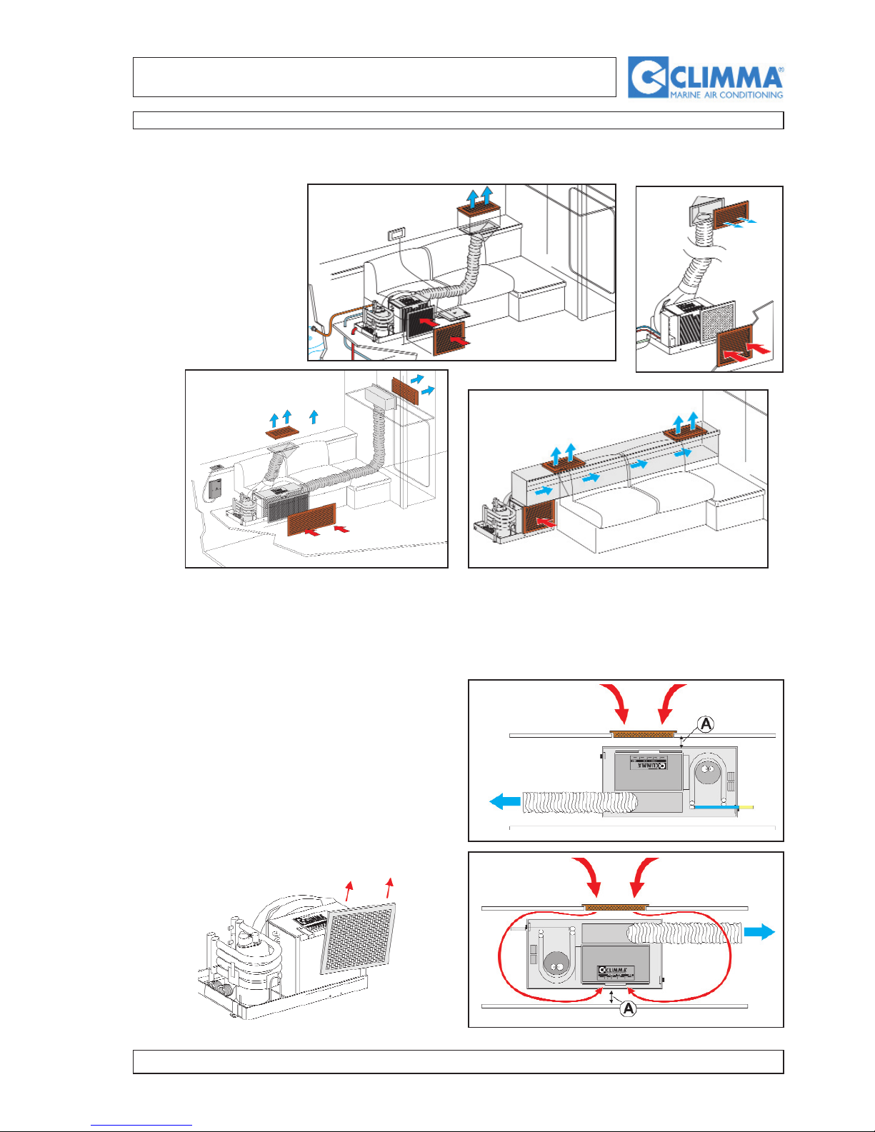
3.2 - ARRANGEMENT - General notes
Version with standard mechanical panel
AIR-CONDITIONERS
COMPACT and SPLIT QUATTRO models
page 6
www.climma.it
C - The exchanger system takes away the ambient
air. The side with the filter mustn’t be in line with the
aspiration grill, as in the picture 1.6. It can have
have also a different position (see the picture 2.6).
The second solution is the best one thanks to the
best sound isolation of the system.
3.3 - PLACING
A.- The unit has been
designed to take the
ambient air directly
away. It must be
installed in a room
that must be conditioned.
B.- The conditioned air (from the fan) must be piped towards one or more grills through flexible
pipes or through isolated ducts of suitable section in the boat structure.
View from above
Figure 1.6
Figure 2.6
View from above
3 INSTALLATION OF THE COMPONENTS
AIR-CONDITIONERS
COMPACT and SPLIT QUATTRO models
page 7
www.climma.it
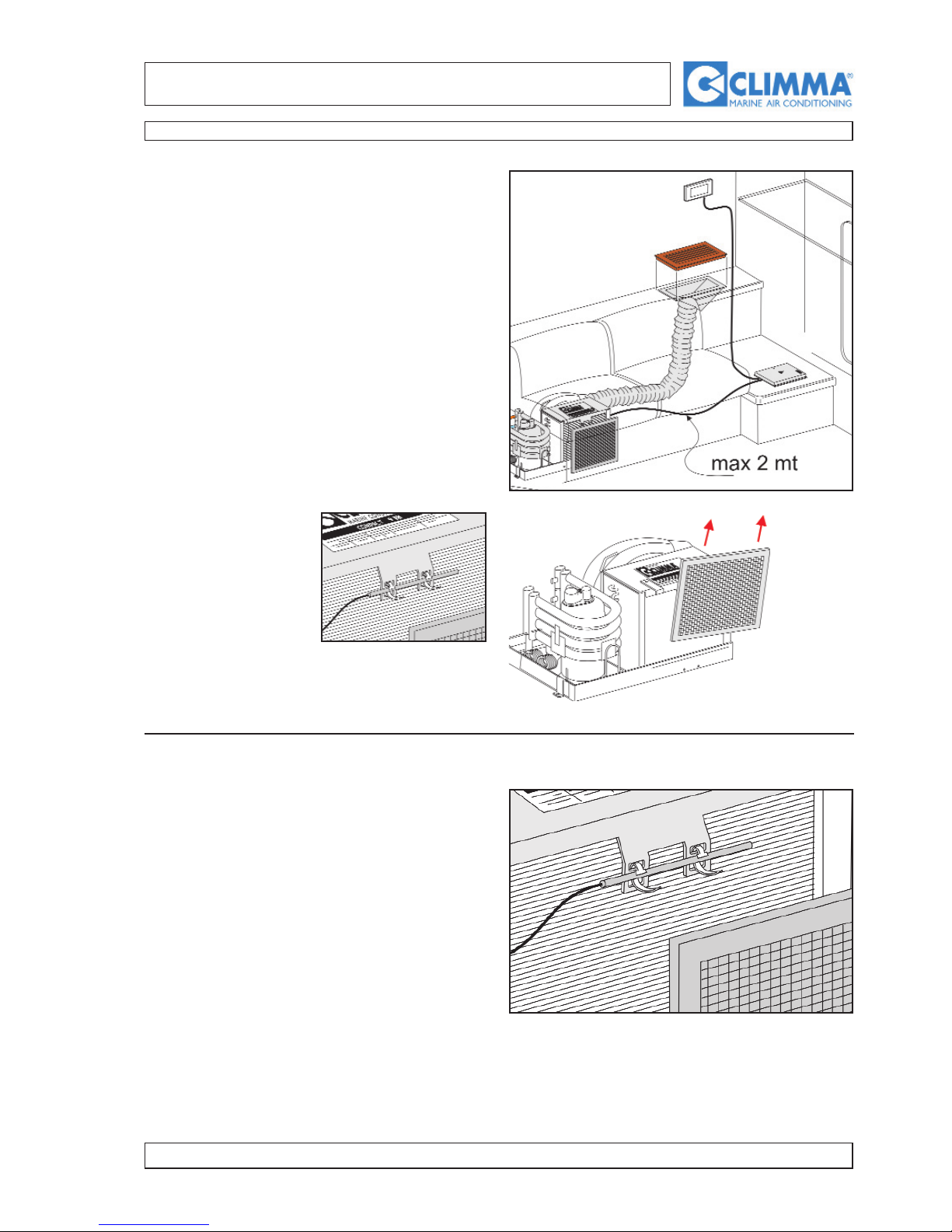
3 INSTALLATION OF THE COMPONENTS
E.- The air-conditioner is connected to the electrical
box through cables of different lenght. So there must
be an accessible space (next to the compressor unit
for SPLIT models) to install the electrical box.
F.- The thermostat bulb and the aspiration filter must
be mounted on the air-refrigerating gas exchanger.
This side must be accessible for the filter maintenance.
G.- The maximum distance between the control panel
and the electrical box is 3 m both for the thermostat
capillary and for the connection cable.
3.4 - THERMOSTAT BULB
The thermostat bulb must be fastened to the air
exchanger by means of special latches.
The bulb must keep separated from the exchanger
because it must be influenced only by the sucked up
air, but not by the refrigerating circuit. Sometimes
you can install the bulb not directly on the exchanger but in the room, so that it is sensitive to the ambient temperature. To fasten the bulb to the wall, you
can use the special plaque.
AIR-CONDITIONERS
COMPACT and SPLIT QUATTRO models
page 8
www.climma.it
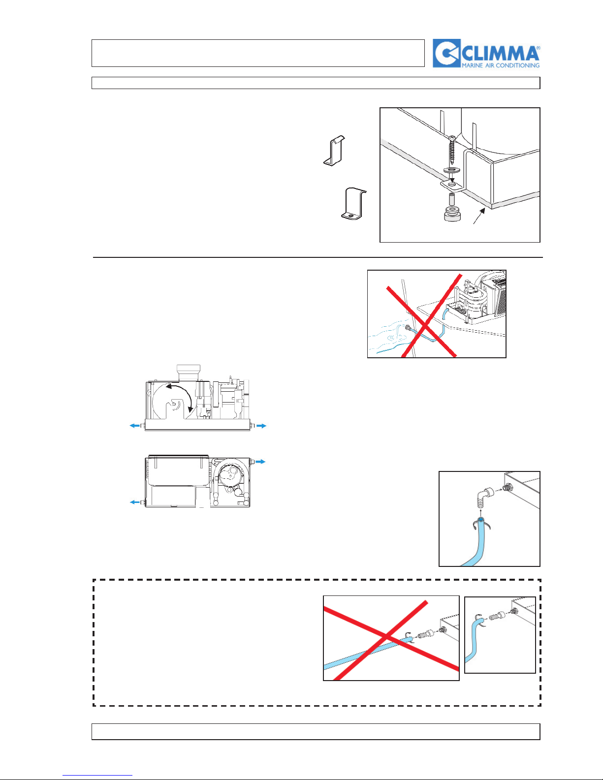
3.5 - FASTENING
The fastening must be executed as indicated.
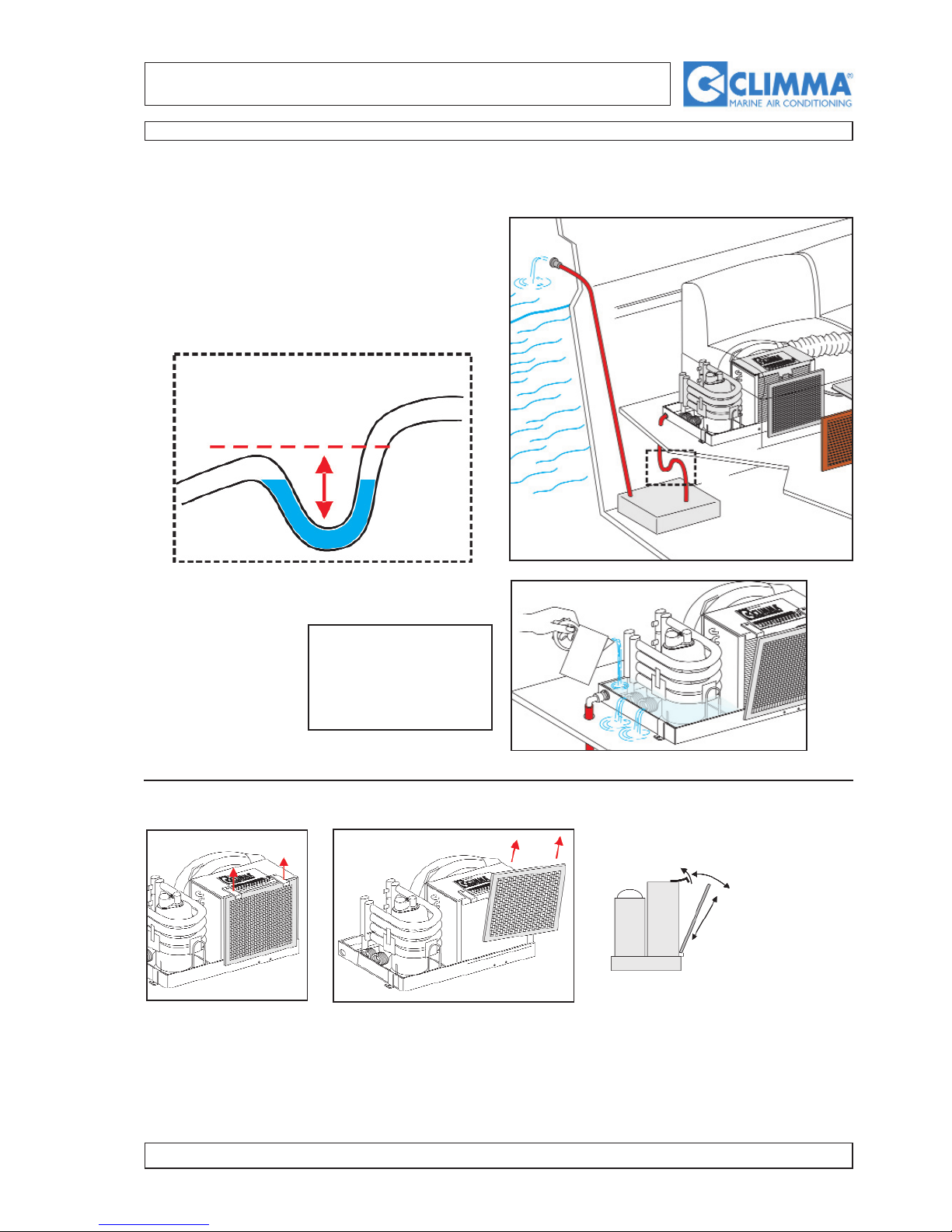
3.6 - CONDENSATION OUTLET
The air-conditioning determines the separation of
the condensation water due to the humidity of the
conditioned air. This condensation must be discharged in the bilge or in a special tank and then by
means of a self-priming pump in the sea.
The water condensation
outlet pipe must be
linked to the rubberholders of 19 mm on the
condensation collection
basin.
Each unit is endowed with two outlets, as you can see in the picture
above.
If the condensation discharge pipe for exigencies
of installation must be long, it is better to use the
special “L” connection. You must avoid such an
installation as you can see in the picture 1.8
because the condensation water can stop and flow
back to the collection basin because of the boat
rocking.
The direct bulkwark outlet is not the best solution: in
fact, it can suck up unpleasant smells due to the
exhaust emissions of its own or of other engines.
Make reference to the safety regulations of the
different countries
NEOPRENE
3 INSTALLATION OF THE COMPONENTS
Figure 1.8
Dis 2.8
Figure 2.8
AIR-CONDITIONERS
COMPACT and SPLIT QUATTRO models
page 9
www.climma.it
Since during the operating the air-conditioner sucks
up and causes a light vacuum in the room, the condensation outlet pipe can suck up from the pilge or
the special tank unpleasant smells that can spread in
the cabin. To avoid this possibility, it is possible to
create a siphon (A) as you can see in the picture 1.9
to stop the air.
To check the actual efficiency of the condensation outlet, pour some
water in the basin.
3.8 - AIR FILTER
The air-conditioner sucks up the ambient air through an air-refrigerating gas exchanger endowed with many
aluminium tongues. They would soon become obstructed because of powder and filth. That’s why you can
mount the air filter directly on the exchanger (as you can see in the picture). The filter must be easily taken off
to clean or replace it.
3.7 - CONDENSATION OUTLET
3 INSTALLATION OF THE COMPONENTS
A
A
Figure 1.9
AIR-CONDITIONERS
COMPACT and SPLIT QUATTRO models
page 10
www.climma.it
3 INSTALLATION OF THE COMPONENTS
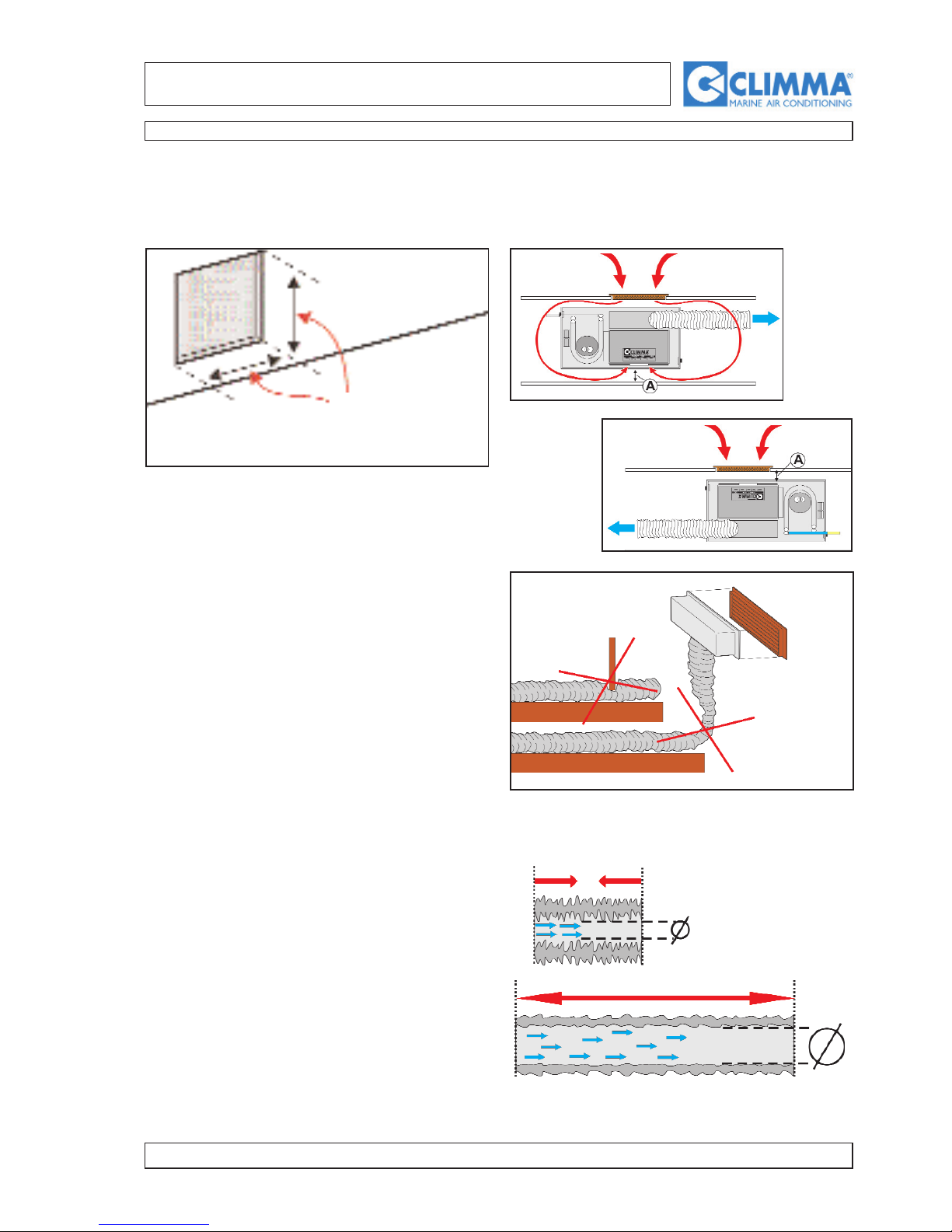
3.9- AIR CIRCULATION SYSTEM (see examples on page 12)
3.9.A - Sucking up
The ambient air is sucked up through one or more
grills of suitable dimensions. The minimum dimensions are 244x244.
(To canalize the air flow back, call the technical
assistance).
min 244 x 244
3.10.B - Air circulation
3.11.B - Air ducts
The efficiency of the installation depends on the air
volume. So it is important to avoid narrow passages
in the air circulation system, keeping the original
diameter dimensions and using short pipes.
The isolated ducts must not be bent so that the air
can circulate currently. Cut out the unuseful lenght.
View from above
Viiew from above

AIR-CONDITIONERS
COMPACT and SPLIT QUATTRO models
page 11
www.climma.it
3 INSTALLATION OF THE COMPONENTS
3.12.C - COMPACT - SPLIT QUATTRO
The fan must be linked by means of a duct to the air
distribution system, that can be constituted of one or
more grills and corresponding plenums. The main
duct diameter must not be inferior to the diameter of
the fan fittings.
The fan can be turned of 90° in case of installation of limited
height.
Example of a Compact installation:
a plenum for air-conditioning two
cabins.
 Loading...