

Page 1
CLIMIA
CTK 240 mobile air dehumidier
Operating manual
Edition 1.0
English
Page 2
Page 3

3
CTK 240 mobile air dehumidier
Contents
Carefully read this operating manual prior to commissioning/using the units!
This operating manual is a translation of the German original.
This manual is an integral part of the unit and must always be kept in the vicinity of the installation location
or on the unit itself.
Subject to modications; no liability accepted for errors or misprints!
1.0 Safety instructions 4
2.0 Environmental protection and recycling 4
3.0 Guarantee 4
4.0 Intended use 4
5.0 Transport and packaging 5
6.0 Air dehumidication 5-7
7.0 Unit description 8
8.0 Set-up 9
9.0 Commissioning 9-12
10.0 Shutdown 12
11.0 Unit transport 12
12.0 Care and maintenance 13-14
13.0 Troubleshooting and customer service 14
14.0 Electrical wiring 15
15.0 Electrical wiring diagram 15
16.0 General view of unit 16
17.0 Spare parts list 17
18.0 Technical data 18
19.0 Maintenance log 19
EC Declaration of Conformity 20
Page 4
4
CLIMIA
1.0 Safety instructions
Carefully read the operating manual
before commissioning the unit
for the first time. It contains useful
tips and notes, as well as hazard
warnings to prevent injury or
material damage . Failure to follow
the instructions in this manual can
endanger people, the environment
and the equipment itself and will
void any claims for liability.
This unit can be used by children
above the age of 8, as well as by
people with impaired physical,
sensory or mental capabilities or a
lack of experience and knowledge
if they are supervised or have
received instruction in the safe
operation of the unit, and if they
understand the associated potential
hazards. Children must never play
with the unit. Cleaning and user
maintenance must not be carried
out by unsupervised children.
Keep this operating manual and the
refrigerant data sheet near to the
units.
The following notes must be
observed in full:
• The units must not be operated
at an ambient temperature
below 5 °C.
• The units may not be set
up or operated in explosive
environments.
• The units must not be installed
or operated in atmospheres
containing oil, sulphur, chlorine,
salt or dust.
• Never insert foreign objects into
the units.
• The units may not be exposed to
direct jets of water.
• An unobstructed air inlet and air
outlet must be guaranteed at all
times.
• The air-inlet grille must always
be kept free of dirt and loose
objects.
• The units must not be covered
during operation.
•
The units must be installed
upright and in a stable position.
•
The units must not be
transported while they are
running.
•
The units may only be
transported upright (water will
escape otherwise).
•
Before each change of location,
the condensate container must
be emptied
•
All electrical cables on the
outside of the units must be
protected against damage (e.g.
by animals etc.)
.
•
Before each change of location,
the condensate containers must
be emptied
.
• Appropriate hazard prevention
measures must be taken to
prevent risks to people when
performing installation, repair,
maintenance or cleaning work on
the units.
• The units and components
should not be exposed to any
mechanical load, extreme levels
of humidity or direct exposure to
sunlight.
3.0 Guarantee
As a prerequisite for any warranty
claims to be considered, it is
essential that the ordering party or
its representative completes and
returns the "certificate of guarantee"
to Climia Intakt GmbH at the time
when the units are purchased and
commissioned.
The guarantee conditions are
listed in the "General terms
and conditions of business and
supply". Furthermore, only the
parties to a contract can conclude
special agreements beyond these
conditions. In this case, contact
your contractual partner in the first
instance.
Disposing of packaging
All products are packed for
transport in environmentally
friendly materials. Make a valuable
contribution to reducing waste
and sustaining raw materials. Only
dispose of packaging at approved
collection points.
Disposing of the units and their
components
Only recyclable materials are used
in the manufacture of the units and
components.
Help protect the environment
by ensuring that the units or
components (for example batteries)
are not disposed of in household
waste, but only in accordance
with local regulations and in an
environmentally safe manner,
e.g.using authorised disposal and
recycling specialists or council
collection points.
2.0 Environmental
protection and
recycling
Page 5

5
CTK 240 mobile air dehumidier
The units are shipped in sturdy
transport packaging. Immediately
check the unit on delivery and make
a note of any damage (please take
photos of the damage) or missing
parts on the delivery note. Inform
the forwarding agent and your
contractual partner.
Please retain the packaging for
returns.
Claims under guarantee made at a
later date will not be accepted.
5.0 Transport and
packaging
4.0 Intended use
The units are designed exclusively
for drying and dehumidication
purposes on the basis of their
structural design and equipment.
The units must not be used for any
other purpose.
The units are only permitted to
be operated by people with the
relevant training and understanding
of how to handle them.
Any different or additional
use is a non-intended use. The
manufacturer/supplier assumes no
liability for damages arising from
non-intended use. The user bears the
sole risk in such cases.
Intended use also includes working
in accordance with the operating
and installation instructions and
complying with the maintenance
requirements.
It is evident that the corrosion rate
below 50% relative humidity (RH) is
low, and below 40% is negligible.
The corrosion rate increases
signicantly above 60% RH.
Thisthreshold for damage as the
result of humidity also applies to
other materials, such as powdery
substances, packaging, wood and
electronic units.
Buildings may be dried in a variety
of ways:
1. By heating and air exchange:
The air in the room is heated in
order for moisture to be removed
and then this air is fed outside.
All of the energy that is involved
is lost together with the moist air
that is released.
2. By air dehumidication:
The moist air that is present
within an enclosed space is
continuously dehumidied
according to the condensation
principle.
The correlations occurring when
air is dehumidied are based on
physical laws.
These are depicted here in graphical
form in order to provide you with
abrief overview of the principles of
air dehumidication.
Using Climia air dehumidiers
•
Even if windows and doors
are well insulated, water and
moisture are still capable of
penetrating thick concrete walls.
•
The water required for setting
in the production of concrete,
mortar and plaster etc. may only
be diused after 1-2 months.
•
Even moisture trapped in the
masonry after high-water or a
ood is released very slowly.
•
The same is also true of moisture
contained in stored materials for
example.
The moisture (water vapour)
released from parts of a building
or materials is absorbed by the
surrounding air. As a result, the
moisture content increases, which
ultimately gives rise to corrosion,
mould, rot, peeling of paint and
other unwanted damage.
By way of example, the diagram
shows the corrosion rate of metal in
dierent levels of humidity.
6.0 Air dehumidication
Page 6

6
CLIMIA
With regard to energy consumption,
air dehumidication has one
distinct advantage:
Energy expenditure is limited
exclusively to the air volumes
present. The mechanical heat that
is released by the dehumidication
process is fed back into the room.
Under normal use, the
air
dehumidier
uses
approximately 25% of the
energy that is required for
the
"heating and ventilating"
principle.
Relative air humidity
Our ambient air is a gaseous
mixture which always contains
acertain volume of water in the
form of water vapour. This volume
of water is specied in g per kg of
dry air (absolute moisture content).
1m3 of air weighs approx. 1.2 kg
at20°C
Depending on the temperature,
each kg of air is only capable of
absorbing a certain volume of
water vapour. Once this capacity
has been reached, the air is referred
to as “saturated” and has a relative
humidity (RH) of 100%.
Relative humidity is understood to
mean the ratio between the current
quantity of water vapour in the air
and the maximum possible quantity
of water vapour at the same
temperature.
The ability of the air to absorb water
vapour increases as the temperature
rises. I.e. the maximum possible
(absolute) water content becomes
greater as the temperature rises.
Building materials and structures
are capable of absorbing
considerable volumes of water,
suchas brick 90-190 l/m³, heavy
concrete 140-190 l/m³ and
limestone 180-270l/m³.
The drying of moist materials such
as masonry is eected as follows:
•
The moisture moves
from the inside of
the material to its
surface
•
Evaporation occurs on the
surface = Transfer of water
vapour to the ambient air
•
The air containing water vapour
is constantly circulated through
the air dehumidier. The air
is dehumidied and, slightly
heated, leaves the unit in order
to re-absorb water vapour
•
In this way, the moisture
contained in the material is
reduced gradually.
The material is dried!
The accumulated condensate is
collected in the unit and drained o
from there.
Drying materials
% RH
Evaporator Condenser
Air temperature
Air direction
Air humidity
Progression
As it ows through or over the evaporator, the air stream is cooled to dew
point. The water vapour condenses, and is collected in a condensate trap
from where it is drained o.
Temp. Water vapour content in g/m3 at humidity of
°C 40% 60% 80% 100%
-5 1.3 1.9 2.6 3.3
+10 3.8 5.6 7.5 9.4
+15 5.1 7.7 10.2 12.8
+20 6.9 10.4 13.8 17.3
+25 9.2 13.8 18.4 23.0
+30 12.9 18.2 24.3 30.3
Page 7

7
CTK 240 mobile air dehumidier
Water vapour condensation
Because the capacity for the
maximum possible volume of
water vapour increases as the air is
heated, the volume of water vapour
contained remains constant and so
relative humidity falls.
In contrast, because the capacity for
the maximum possible volume of
water vapour decreases as the air is
cooled, the volume of water vapour
contained remains constant and so
relative humidity increases.
If the temperature continues to
fall, the capacity for the maximum
possible volume of water vapour
is reduced so much so that it is
ultimately equal to the volume of
water vapour contained in the air.
This temperature is referred to as
the dew point. If the air is cooled to
below the dew point, the volume of
water vapour in the air will become
greater than the maximum possible
volume of water vapour.
At this point, the water vapour
begins to precipitate.
This condenses to water and
moisture is removed from the air.
Examples of condensation include
steamed-up window panes in
winter, or the moisture on the
outside of a cold drinks bottle.
As the relative humidity of the air
increases, so too does the dew
point, making it easier for the
temperature to fall below it.
Condensation heat
The Energy transferred to the air
from the condenser consists of:
1. The amount of heat derived
beforehand in the evaporator.
2. The electrical drive energy.
3. The condensation heat released
by liquefying the water vapour.
Energy must be supplied when
liquid is converted into a gas. This
energy is designated as evaporation
heat. It does not cause any increase
in temperature, but is required
to convert a liquid into a gas.
Conversely, energy is released when
gas is liqueed, this is designated as
condensation heat.
The amount of energy from
evaporation heat and condensation
heat is the same.
For water, this is:
2250 kJ/kg (4.18 kJ = 1kcal)
From this it is evident that the
condensation of water vapour
causes a large quantity of energy to
be released.
If the moisture that it is to be
condensed is not introduced by
evaporation in the room itself,
but from outside, e.g. through
ventilation, the condensation heat
released contributes to the heating
of the room. With drying operations,
a heat cycle is created, whereby
heat is consumed for evaporation
and released for condensation.
When dehumidifying fed air,
alarger contribution of heat is
created, which manifests itself as
atemperature increase.
Generally speaking, the time
required for the drying process is
not only dependent on the output
of the unit, but is determined to
a greater extent by the speed at
which the material or building
section loses its moisture.
Page 8

8
CLIMIA
nozzle into the condensate
container below either continuously
or only during the defrosting
phases.
A oat is installed inside the
condensate container. In the event
that the container is full, the oat
will activate a microswitch which
will switch o dehumidication
mode.
The units switch o and the
“container full” indicator light on
the control panel illuminates.
Thisextinguishes again when
theempty condensate container
isre-inserted.
The units then restart.
In unattended continuous operation
with an external condensate
connection, the condensate that
occurs is drained continuously via
a hose connection. The units then
start.
In unattended continuous operation
with an external condensate
connection, the condensate that
occurs is drained continuously via
ahose connection.
Recirculating fan
Condensate
container
Condenser
Evaporator
Condensate trap
Compressor
Moist room air
Dehumidied
room air
Fig. 1 Schematic depiction of the workings of the air dehumidier
7.0 Unit description
In dehumidication mode, one of
the “Fan stage” indicator lights on
the control panel illuminates.
The fan extracts the moist room air
through the intake grill with lter,
evaporator and the condenser
behind.
Heat is removed from the room air
on the cold evaporator. The air is
then cooled to below dew point.
The water vapour contained in
the room air is then deposited
as condensate or rime on the
evaporator ns.
On the condenser (heat exchanger),
the cold and dehumidied air is
warmed up again and discharged
back into the room via the outlet
grill with a temperature increase of
around 5 - 10°C above the room
temperature.
The processed, dry air then re-mixes
with the room air.
Continuous circulation of the room
air through the unit gradually
reduces the relative humidity (% RH)
in the room to the desired humidity
level.
Depending on the room air
temperature and the relative
humidity, condensed water will drip
into the condensate trap and then
through the integrated discharge
The units have been designed for
universal and straightforward air
dehumidication.
Their compact dimensions allow the
unit to be transported and set up
with ease.
The units operate in accordance
with the condensation principle and
are equipped with a hermetically
sealed refrigerant system, heat gas
defrosting, low-noise and lowmaintenance fan and connection
cable with plug.
The fully automatic control, the
variable hygrostat, the condensate
container with integrated overow
protection and the connection
nozzle for condensate drainage
guarantee fault-free continuous
operation.
The units conform to the
fundamental health and safety
requirements of the appropriate EU
stipulations.
The units are dependable and oer
ease of operation.
The units are used in all locations,
where dry air s a must and where
economic consequential damage
(such as that caused by mould)
must be prevented.
The units may be used for the
drying and dehumidication of
areas such as:
•
Living rooms, bedrooms, shower
rooms or cellar rooms
•
Laundry rooms, weekend homes,
caravans
•
Warehouses, archives,
laboratories
•
Bathrooms, wash rooms and
changing rooms etc.
•
Basements, storage rooms
Operating sequence
The units are switched on and o by
the power key.
Page 9

9
CTK 240 mobile air dehumidier
8.0 Set-up
For the best economic and safe use
of the units, the following notes
must be followed in full:
•
The units must be set up in an
upright and level position, to
ensure that the condensate can
drain freely
•
To ensure optimum air
circulation, the units should be
set up in the centre of the room,
where possible
•
Ensure that the room air can
be sucked in and discharged
without hindrances
•
Observe a minimum clearance of
50 cm from walls at all times
•
Units must never be set up in the
immediate vicinity of heaters or
other sources of heat
•
Air circulation is improved if the
unit is set up approx. 1 m above
the ground
•
The room being dried or
dehumidied must be closed to
the surrounding atmosphere
•
Avoid having opened windows
and doors etc., and avoid
frequent entry to or exit from the
room as much as possible
•
The units may not be used in
environments containing a
great deal of dust or chlorine,
or in places with atmospheres
containing ammonia
•
The output of the unit is
entirely dependent on the
conditions inside the room, room
temperature, relative humidity
and observance of the set-up
instructions
Min. 0.5m
distance to wall
Maintain adequate clearance from
heaters or other sources of heat.
Keep windows and doors closed!
Fig. 2 Schematic depiction of how to set up the air dehumidier
9.0 Commissioning
Before commissioning the unit or if
local requirements dictate, the airinlet grill and air-outlet grill must be
checked for contamination.
Important notes prior to
commissioning
•
All extensions to the electrical
connection must be of
asucient cable size and must
only be used fully rolled out or
unrolled
•
Never use the power supply
connection cable as a pull cord
•
After being switched on,
theunits operate fullyautomatically until switched o
by the hygrostat or oat when
the condensate container is full
•
The condensate container must
be inserted properly
The unit cannot be operated
if the condensate container
isnot inserted properly!
•
In order to prevent damage to
the condenser, the units are
equipped with a mechanism that
prevents the compressor being
immediately switched back on
after it is switched o
The units do not switch back
on until a waiting time of
around 3 minutes has elapsed!
•
If the units work in continuous
operation with an external
condensate drainage
connection, refer to the relevant
section
NOTE
A contaminated grille or lter
must be cleaned or replaced
immediately.
Page 10
10
CLIMIA
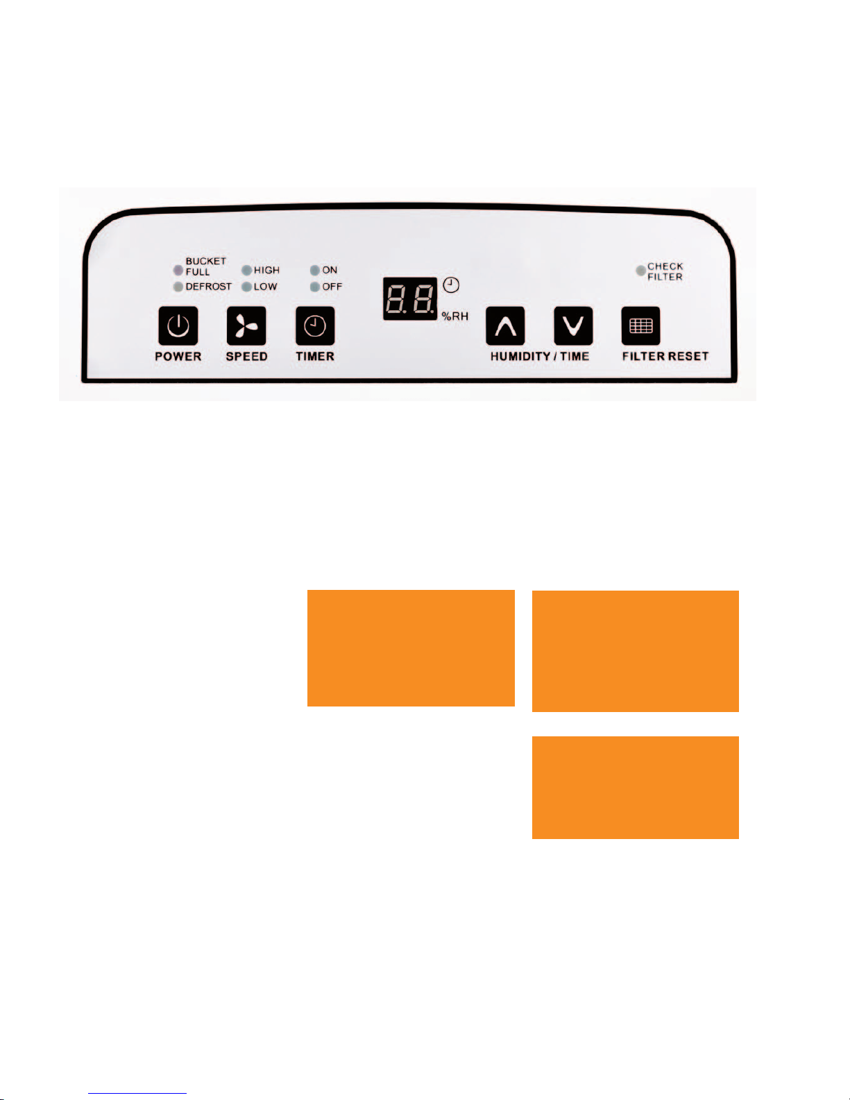
1. The power key switches the unit
on and o.
2. The speed key sets the fan stage.
The min/max fan stage indicator
lights indicate the fan stage at
which the unit is running.
3. If required, the unit can be
switched to manual timer mode
using the timer key.
4. Use the “Humidity/Time” arrow
keys to set the required air humidity
in the installation room or the
required air humidier operating
time.
5. After an operating time of
250hours, the “Check Filter”
indicator light illuminates and the
lter must be removed and cleaned
according to the instructions. The
unit can be reset using the lter
reset key after inserting the lter.
6. The display shows the current
air humidity or the required air
humidity during regulation, or the
required operating time. The display
shows the current air humidity
again 10 seconds after the setting is
made.
NOTE
In room temperatures below
10°C
and relative humidity
below
40%
, economical use
of the unit can no longer be
guaranteed.
NOTE
After setting the required air
humidity, the display shows
this for another 10 seconds
before displaying the current air
humidity again.
NOTE
Note that the compressor does
not switch on until a waiting
time of 3 minutes has elapsed.
Restart protection!
Control panel
The control panel contains various keys, indicator lights and a display.
7. The bucket full indicator light
indicates when the condensate
bucket is full and must be emptied.
8. The unit is in defrost mode while
the “Defrost” operating light is
illuminated.
Commissioning the units
1. Connect the unit's electrical
connection to a properly installed
mains socket.
2. Press the power key once to
switch on the unit.
3. Use the arrow keys to set the
required air humidity of the
installation room.
The air humidity can be set at
increments of 5 %.
The recommended approximate
setting values are listed in the
adjacent section.
Adjusting units/moisture
The unit’s dehumidication power
is entirely dependent on the
conditions inside the room, the
room temperature, the relative
humidity and observance of the
notes in the “Setting up” chapter.
Page 11

11
CTK 240 mobile air dehumidier
The following notes must also be
observed in full:
•
Ensure that the air can discharge
without hindrances
This is the only way to
guarantee optimum unit
operation!
•
Ensure that sensitive objects
such as house plants are not
placed directly in the air ow
emerging from the unit.
Automatic defrost system
The moisture contained in the
room air condenses when cooling
and coats the evaporator ns with
rime or ice depending on the
air temperature and the relative
humidity (% RH).
The automatic defrost system that is
integrated in the unit switches the
defrost cycle on if required.
The rime or ice that has
accumulated on the exchanger
surfaces is defrosted using
electronic circulation mode as
required.
This tried and tested defrosting
method guarantees high
dehumidication performance.
Dehumidication mode is paused
during the defrost phase.
The “Defrost mode” indicator light
indicates that the defrost cycle is
running.
The higher the room temperature
and relative air humidity, the higher
the dehumidication power.
A relative humidity of around
45to60% is sucient in living
rooms. The air humidity should not
exceed 40 to 45% in
warehouses, archives, etc.
Timer function
The units feature an integrated
timer function.
Pressing the timer key switches the
unit’s automatic mode on and o.
If automatic mode is switched o,
the arrow keys can be used to set
the required operating time.
The operating time can be set for a
maximum of 24 hours in increments
of an hour.
The unit will switch itself o
automatically after the set time has
elapsed.
NOTE
If the room temperature is
suciently high (>12 °C), the
surface of the ns will not be
cold enough for rime formation
to occur, rendering defrosting
unnecessary.
Therefore, the air dehumidier
works economically.
Emptying the condensate
container
The integrated condensate
container must be emptied from
time to time.
Dehumidication mode is switched
o if the condensate container is
full.
The “BUCKET FULL” indicator light
indicates that the unit has switched
o.
1. Pull the full container forwards
and out carefully.
2. Pour the water into a drain.
3. Re-insert the emptied container
carefully into the unit.
The “BUCKET FULL” indicator light
extinguishes and the unit continues
to run automatically.
NOTE
For economical and technical
reasons, the units must not
be operated at an ambient
temperature below 5 °C.
NOTE
After being emptied, the
condensate container incl. oat
must be checked for damage,
contamination etc.
NOTE
The unit can only be started once
the condensate container has
been inserted correctly.
NOTE
The devices can be switched ON
and OFF via an external timer or
a Smart Home socket if required.
Page 12

12
CLIMIA
Press the power key once to switch
on the unit.
If the units are inactive for long
periods, disconnect them from the
mains power supply.
Empty the condensate container
completely and dry with a clean
cloth.
Beware of dripping condensate!
The units must be cleaned and
dried completely before storing.
When storing the unit, cover with
a plastic sheet/foil if necessary
andstore in an upright position
inasheltered and dry location.
The units are only permitted to be
stored upright in a suitable storage
location that is protected against
dust and direct sunlight.
Continuous operation with
external condensate outlet
The units are equipped with a
special connection nozzle on the
rear.
A standard 1/2” water hose can be
connected to this.
1. The condensate hose connection
must be switched o rst for this
purpose. The rubber stopper can
then be removed.
2. Pull the condensate hose
connection over a suciently long
and suitable drain hose.
3. Connect the drain hose to the
connection nozzles and tighten the
condensate hose connection by
hand.
In unattended permanent operating
mode, the condensate should
preferably be drained into a lowerlevel drain.
If using an external collection
container (pan, bucket, etc.),
theunit must be placed at a correct
height.
10.0 Shutdown
The units are equipped with four
foot rollers and two additional
handles for easy and convenient
transport.
•
Before each change of location,
switch o the unit and remove
the power plug from the mains
socket
•
Empty the condensate bucket
completely.
•
If residual moisture remains on
the evaporator or water remains
in the condensate container, the
units must only be transported in
an upright position
•
The transport rollers are only
suitable for use on level and
smooth ground
•
The units must be carried when
transporting on rough terrain or
uneven surfaces
11.0 Unit transport
CAUTION!
There is no unit overow
protection in this variant.
CAUTION!
Ensure that the drainage hose is
placed at an incline to the drain
to allow the condensate to drain
without hindrance!
NOTE
Beware of dripping condensate.
After switching o the units, the
evaporator may continue to
defrost under the inuence of the
ambient temperature.
CAUTION!
The mains cable must never
be used as a pull cord or xing
device.
Page 13

13
CTK 240 mobile air dehumidier
All moving parts have a lowmaintenance permanent
coat of lubricant. The entire
refrigerant system is designed as
a maintenance-free, hermetically
sealed system and may only be
repaired by a specialist.
•
Observe the regular care and
maintenance intervals
•
In accordance with the operating
conditions, the units must be
checked as required but at least
yearly by a specialist to ensure
that they are in a condition that
is safe to use
•
Only clean the units with a dry or
damp cloth
Do not use a water jet!
•
Never use abrasive or solvent-
based cleaners
•
Even with heavy contamination,
use only suitable cleaners
•
Check the inlet and outlet grille
for contamination on a regular
basis
Clean or replace if required!
12.0 Care and maintenance
Cleaning the condenser and
evaporator
The unit housing must be opened
to allow the inside of the unit to be
cleaned and to provide access to
electrical components.
•
Clean the condenser and
the evaporator by blowing,
vacuuming or using a soft brush.
Do not use water jets!
•
Clean the interior surfaces on the
units, the condensate traps with
hose connection, the fan and the
fan housing carefully
•
Check all unit components for
damage and repair if necessary
•
Carefully ret all parts that were
removed in reverse order
NOTE
Regular care and maintenance
is fundamental to a long service
life and fault-free operation of
the unit.
CAUTION!
Before undertaking any work on
the units, the power plug must be
removed from the mains socket.
NOTE
Adjustment and maintenance
work may only be carried out
by authorised and qualied
technicians.
NOTE
When cleaning the exchanger,
particular care must be taken
because the ne aluminium ns
bend very easily.
CAUTION!
An electrical safety check must
be carried out in accordance with
VDE0701 after any work on the
units.
Filter cleaning
To prevent damage to the unit, it is
equipped with an intake grill with
integrated air lter.
In order to prevent power losses
or unit faults, the intake grill with
lter must be inspected as required,
but every 2 weeks at the latest,
andcleaned if necessary.
1. Use the “POWER" key to switch
the unit o.
2. Remove the power plug from the
mains socket.
3. Reach into the recessed grip and
remove the air lter.
4. Clean the air lter with lukewarm
water or a vacuum cleaner.
CAUTION!
The unit is not permitted to be
operated without the air lter
tted!
Page 14

14
CLIMIA
13. 0
Troubleshooting
The units are manufactured
using state-of-the-art production
methods and tested several times to
verify their correct function.
However, if a functional fault
should occur, the unit should rst
be checked in accordance with the
following list.
5. Heavier contamination may be
remedied by rinsing the lter
in a lukewarm (max. 40°C) soap
solution.
Finally, always rinse the lter
carefully with clear water and
allow to dry!
6. Also check the intake grill for
contamination and clean if
necessary.
7. Before retting grill and lter,
ensure that they are fully dry
and that no damage has been
sustained.
The unit runs but condensate is
not formed:
•
Check the room temperature.
The operating range of the unit is
between 5 °C and 32°C
•
Check the air humidity
min.30%RH required
•
Check the intake grill and air
lter for contamination
Clean or replace if required!
•
Have the heat exchanger ns
checked for contamination
This work requires the unit to
be opened and must therefore
only be carried out by an
authorised specialist company!
The unit is loud or condensate
runs out:
•
Check whether the unit is on
astable and even base
•
Check whether the unit is
standing upright and stably
•
Have the condensate trap or
the connection nozzles checked
to see whether there are dirt
deposits on them
This work requires the unit to
be opened and must therefore
only be carried out by an
authorised specialist company!
NOTE
Heavily contaminated or
damaged air lters must be
replaced with new parts.
Only original spare parts may be
used.
NOTE
Adjustment and maintenance
work may only be carried out
by authorised and qualied
technicians.
The unit does not start:
•
Check the hygrostat’s setting
The set value must be lower
than the relative humidity in the
installation room!
•
Check the power supply and
the power fuse provided by the
customer 230V/1~/50 Hz
•
Check the power plug and the
cable for damage
•
Check the condensate bucket’s ll
level and seating
The “Bucket full” indicator light
must not be illuminated!
•
Check that the microswitch [MS]
on the condensate bucket is
functioning
•
Check that the inlet and outlet
are free Overheating!
•
Check the fuse on the control
board
NOTE
The units work with
environmentally-friendly and
ozone-neutral R134a refrigerant.
The mixture of refrigerant and oil
within the unit must be disposed
of properly in accordance
with the statutory or locallyapplicable regulations.
NOTE
If the unit fails to function
correctly after the checks have
been carried out, contact an
authorised specialist.
CAUTION!
Work on the refrigerant system
and on the electrical equipment
must only be conducted by a
specially authorised specialist!
Page 15

15
CTK 240 mobile air dehumidier
15.0 Electrical wiring diagram
•
The units are operated with
230V / 50 Hz alternating current
•
The electrical connection is
established using a built-in
mains cable with earthed safety
plug
•
Extensions to the connection
cable may only be carried out by
authorised electricians, subject
to the length of the cable,
connected load of the unit and
taking into consideration how
the unit is used at its location
CAUTION!
All cable extensions must only be
used in fully unreeled or reeled
o condition.
NOTE
The electrical connection to the
units must be made at feedpoints
with residual current devices
in accordance with VDE 0100,
Section 704.
When installing the units in
extremely damp environments
such as laundry rooms, showers
etc., the unit must secured
with aresidual current device
provided by the customer in
accordance with the regulations.
14. 0 Electrical wiring
CN 1
NO
HUMIDITY SENSOR /
HYGROSTAT
COM.
CN 3
L
L
N
E
CN 4
CN 2
CN 1
POWER SUPPLY
T1A L 250V
H
COMPRESSOR
OL P
CN 7
N
N
P6
P3
P4
P5
TEMPERATURE PROBE
SWITCH
FAN
MOTOR
CONDENSER
CONDENSER
CONTROL BOARD
FUSE
BLUE
BLUE
BLUE
YELLOW / GREEN
BROWN
WHITE
RED
YELLOW
RED
BLUE
WHITE
BLACK
Page 16

16
CLIMIA
16.0 General view of unit
We reserve the right to modify the dimensions and design as part of the ongoing technical development process.
2
1
4
3
5
6
7
8
10
11
12
37
3
32
31
30
26
47
45
44
43
41
39
38
49
50
51
9
46
40
42
16
33
21
13
23
24
22
Page 17

17
CTK 240 mobile air dehumidier
17.0 Spare parts list
When ordering spare parts, please always state the EDP no. and unit number (see name plate)!
No. Designation EDP no.
1 Floor pan
2 Conveyor rollers
3 Compressor, cpl.
4 Vibration dampers
5 Suction pipe
6 Drain line
7 Centre wall
8 Condensate trap
9 Evaporator, complete.
10 Condenser, complete.
11 Capillary
12 Y-pipe
13 Condenser, (for compressor), complete)
16 Microswitch
21 Condensate trap cover
22 Fan housing
23 Fan wheel
24 Fan motor
26 Distribution block
30 Control board
31 Conductor board / board
32 Probe (evaporator/EVAP)
33 Hygrostat
34 Condenser (fan motor)
37 Mains cable with plug
38 Front wall
39 Back wall
40 Transport handle
41 Top cover
42 Intake grill
43 Air lter
44 Condensate bucket cover
45 Condensate container
46 Float, cpl.
47 Transport handle (condensate bucket)
49 Rubber stopper
50 Condensate hose connection
51 Control panel
Page 18

18
CLIMIA
18.0 Technical data
1)
Contains greenhouse gas according to Kyoto protocol
2)
Noise level measurement DIN 45635 - 01 - KL 3
Series CTK 240
Operating range, temperature °C 5 to 32
Operating range, humidity % RH 30 to 90
Dehumidication capacity max. l/day 30
At 27 °C/60 % RH l/day 18
Fan stages 2
Max. airow volume m3/h 240/186
Condensate container capacity Litres 6.3
Refrigerant
1)
--- R134A
Refrigerant quantity g 200
Power supply V/~/Hz 230/1/50
Max. rated current consumption A 4.1
Max. power consumption kW 0.57
Sound pressure level LpA 1m 2) dB (A) 46/41
Dimensions
Depth mm 272
Width mm 384
Height mm 610
Weight kg 17
We reserve the right to modify the dimensions and design as part of the ongoing technical development process.
Page 19
19
CTK 240 mobile air dehumidier
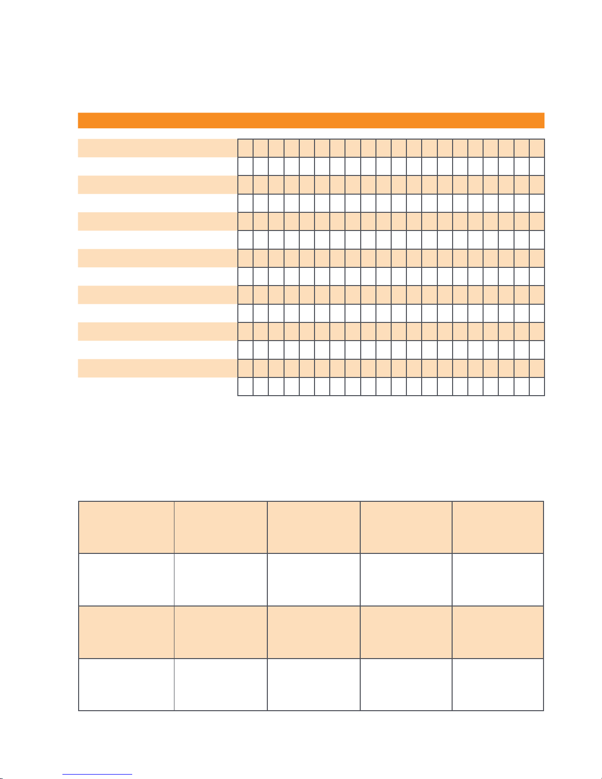
19.0 Maintenance log
Unit to be maintained only by authorised specialists in accordance with the statutory regulations.
✍
Unit type: .................................. Unit number: ...................................
1 2 3 4 5 6 7 8 9 10 11 12 13 14 15 16 17 18 19 20
Unit cleaned - outside -
Unit cleaned - inside -
Fan blade cleaned
Fan housing cleaned
Condenser cleaned
Evaporator cleaned
Fan function checked
Air-inlet grid with lter cleaned
Unit checked for damage
Safety devices checked
All fastening screws checked
Electrical safety check
Test run
1. Date: ..............
..............................
Signature
2. Date: ..............
..............................
Signature
3. Date: ..............
..............................
Signature
4. Date: ..............
..............................
Signature
5. Date: ..............
..............................
Signature
6. Date: ..............
..............................
Signature
7. Date: ..............
..............................
Signature
8. Date: ..............
..............................
Signature
9. Date: ..............
..............................
Signature
10. Date: ............
..............................
Signature
11. Date: ............
..............................
Signature
12. Date: ............
..............................
Signature
13. Date: ............
..............................
Signature
14. Date: ............
..............................
Signature
15. Date: ............
..............................
Signature
16. Date: ............
..............................
Signature
17. Date: ............
..............................
Signature
18. Date: ............
..............................
Signature
19. Date: ............
..............................
Signature
20. Date: ............
..............................
Signature
Comments: .....................................................................................................................................................
.............................................................................................................................................................................
.............................................................................................................................................................................
Page 20
20
CLIMIA
EC – Declaration of Conformity
Original Declaration of Conformity
We do hereby declare that the units named below, produced and sold by us, satisfy the relevant basic requirements
of the EC Directives, the EC safety standards and other product-specic EC standards.
Name of Manufacturer: Intakt GmbH
Climia - Air conditioning and heating technology
Niemeierstraße 13
D - 32758 Detmold, Germany
Name of the CE representative: Intakt GmbH
Climia - Air conditioning and heating technology
Niemeierstraße 13
D - 32758 Detmold, Germany
Unit (machinery) model: Air dehumidier
Series/ Class: CLIMIA CTK 240
Series/ Class Number: 1803...
Delegated regulations (EU): 2011/65/EU:2011
2014/30/EU:2014
2014/35/EU:2014
Applicable standards: DIN EN 12102-1:2018
DIN EN 55014-1:2017; DIN EN 55014-2:2015
DIN EN 60335-1:2012; DIN EN 60335-2-40:2014
DIN EN 61000-3-2:2015; DIN EN 61000-3-3:2014
DIN EN 62233:2008
Detmold, 19th June 2018 Intakt GmbH
................................................................
Managing Director’s signature
Page 21

21
CTK 240 mobile air dehumidier
Notes
Page 22

22
CLIMIA
Page 23

23
CTK 240 mobile air dehumidier
Page 24

Intakt GmbH
Climia - Klima- und Wärmetechnik
Niemeierstraße 13
D - 32758 Detmold
 Loading...