

ClimExel M.P.I.-100M, M.P.I.-190M, M.P.I.-160M, M.P.I.-80M, M.P.I.-240T Installation Instructions Manual
...
23/96
2016/03 - Indice de révision : E - Code : 0033340
SWIMMING POOL
HEAT PUMPS
MPI - 80M .MPI - 100M .MPI - 160M . MPI - 190M / MPI - 190T
MPI - 240M / MPI - 240T . MPI - 320T . MPI - 380T
INSTALLATION INSTRUCTIONS AND RECOMMENDATIONS
(To be read carefully and kept for future reference)
You have just purchased a CLIMEXEL heat pump, thank-you for placing your trust in us. This product is
one of the best available on the market. Before installing and using the product, please read the following
information carefully. It contains important recommendations concerning the various manipulations as well
as some useful advice. Keep this document in a safe place and show it to any other users.
FR
GB
DE
NL
p.1
p.23
p.45
p.69

24/96
2016/03 - Indice de révision : E - Code : 0033340
I. Operating principal and main component ................................... Page 25
II. Recommendations concerning safety and general operation .. Page 27
III. Siting and installation ................................................................. Page 28
IV. Hydraulic connections ................................................................ Page 32
V. Wiring ............................................................................................. Page 33
V.1 – connections on the electrical panel side ....................... Page 34
V.2 – connections on the heat pump side............................... Page 34
V.3 – Slaving filtration ............................................................. Page 35
VI. Start up and operation of the heat pump ....................................... Page 35
VI.1 – The IC 121 CX regulator .............................................. Page 35
VI.2 – Keypad functions ......................................................... Page 35
VI.3 – Display ......................................................................... Page 36
VI.4 – Start up of the machine................................................ Page 37
VI.5 – Shutting down the machine.......................................... Page 37
VI.6 – Viewing and regulating the set point ............................ Page 38
VI.7 – Switching between Eco or Confort mode ...................... Page 38
VI.8 – Controlling the flow rate through the by-pass loop ....... Page 39
VI.9 – Initial heating phase ..................................................... Page 39
VI.10 – Regulation phase ....................................................... Page 39
VI.11 – Thermodynamic defrosting cycles ............................. Page 40
VII. Periodic maintenance ................................................................... Page 40
VIII. Winterizing ................................................................................... Page 41
IX. Troubleshooting .............................................................................. Page 41
X. Alarms ............................................................................................ Page 42
XI. Wiring schematics ......................................................................... Page 42
XII. Guarantees ................................................................................... Page 44
Table of contents

25/96
2016/03 - Indice de révision : E - Code : 0033340
I. Operating principal and main components
This paragraph describes how Climexel heat pumps work. An understanding of the workings of the heat pump will help
you realise the importance of the preparation work that must be carried out before installing, using or maintaining your
heat pump.
A heat transfer fluid (R 410 A) travels in a continuous loop through a copper circuit. As it moves through the circuit it
experiences the following cycle:
1) captures calories from ambient air as it flows over the fin-type “evaporator”. The fan propels
ambient air over aluminium fins covering the copper tubes through which the liquid is flowing; the fluid
is heated by the ambient air which, in turn, is cooled down.
2) the fluid enters the “compressor”, here the fluid pressure is raised significantly thus further increasing its
temperature (all models except the MPI-160 are fitted with a Scroll type compressor)
3) the fluid passes into the “condenser” or plate type heat exchanger where calories are transferred from
the heat transfer fluid to the pool water, the fluid is cooled while the pool water is heated.
4) the fluid returns to its initial temperature and pressure in the expansion chamber and the cycle starts
again
The compressor and expansion chamber delimit two half-loops:
- the half-loop situated on the condenser side is referred to as the HP or High Pressure loop
- the half-loop situated on the expansion chamber side is referred to as the LP or Low Pressure loop
With an ambient air temperature of 15°C, CLIMEXEL heat pumps transfer 4 to 5 times more energy to the pool water
than they consume (90% of this energy is consumed by the compressor): these machines have a yield (or COP Coefficient of Performance) of between 4 and 6.
Heat is transferred to
the pool water from
the heat transfer fluid
within the plate-type
heat exchanger.
Pool water
The fan draws ambient air
in from the outside and
over the evaporator where
it heats up the heat transfer
fluid
The compressor increases
the pressure of the heat
transfer fluid and thus
raising its temperature
further
POWER INVERTER SYSTEM
On the contrary to the fixed speed (50 Hz) compressor equipping conventional On/Off hat pumps, the speed of the
inverter compressor can vary between 11 and 100 Hz.
Thus, when the ambient air temperature is low, or the heating demand is high, the inverter compressor runs at high
speeds (between 50 and 100 Hz). Inversely, when the heating demand is low, notably when the pool water
The expansion chamber
decreases the pressure of
the fluid thus lowering its
temperature

26/96
2016/03 - Indice de révision : E - Code : 0033340
As the ambient air temperature increases, more calories are transferred to the heat transfer fluid at the evaporator, and
then from the heat transfer fluid to the pool water in the condenser. Inversely, as the ambient air temperature falls, less
calories will be available for transfer to the pool water.
To provide a general idea, the following reduction coefficients should be applied to the power values quoted for an
ambient air temperature of 15°C if the machine is operated at lower temperatures.
To ensure correct operation and safety, CLIMEXEL heat pumps are fitted with several safety mechanisms:
- water flow controller, controls the flow of pool water entering into the condenser: shuts down the heat pump if
the water flow drops below a certain rate or stops completely (not enough calories being transferred from the
heat transfer fluid) ;
- LP pressure gauge, on the LP loop: stops the heat pump if the gas pressure is too low and allows the heat
pump to restart automatically when the pressure returns to normal, within the limit of 3 stop/start cycles per hour,
otherwise switches to fault mode (LP alarm)
- HP pressure gauge, on the HP loop: shuts down the heat pump if the gas pressure is too high, the machine
switches to fault mode;
- CLIMEXEL POWER INVERTER heat pumps feature numerous electronic safety mechanisms.
Start up of the compressor and evaporator is controlled by a regulator that allows:
- the user to choose a temperature (the set-point) to which the pool water should be heated;
- automatic start up of the machine if the pool water temperature drops below the set-point (unless filtration is
stopped and is not slaved to the heat pump) ;
- automatic shut down of the machine once the pool water reaches the set-point
- selection of the operating mode; Comfort or Eco
- selection of the configuration; heat or chill the pool water
temperature is around the set point, the Inverter compressor runs at low speed (between 11 and 50 Hz).
Operating at low speeds, the noise level is extremely low, the COP is optimised and the service life of the compressor
is extended.
Note: the actual operating range varies depending on the heat pump model.
The power levels or "STEPs" are managed automatically by the machine, they can be viewed from the thermostat
menu. STEPs range from 0 to 7, the higher the STEP the higher the machine's power level.
The machine features a safety mechanism that allows it to switch to a higher power level if it is taking too long for pool
water to reach the set point.
Note:
In Comfort mode, the machine will run at full power until the set point is reached.
In Eco mode, the machine will regulate its power as a function of the air and water temperatures in order to optimise
power consumption. In Eco mode it will take longer for the pool water to reach the set point than in Comfort mode.
*Values indicated under the following conditions: temperature of the ambient air temperature 15°C and water at 26°C
M.P.I.-80M M.P.I.-100M M.P.I.-160M M.P.I.-190M M.P.I.-190T M.P.I.-240M M.P.I.-240T M.P.I.-320T
M.P.I.-380T
Maximum heating power*
8 kW 10 kW 16 kW 19 kW 19 kW 24 kW 24 kW 32 kW 38 kW
Quantity of gas
2.1 Kg 2.1 Kg 3.2 Kg 4.6 Kg 4.6 Kg 4.6 Kg 4.6 Kg 7.1 Kg 7.7 Kg
M.P.I.-80M M.P.I.-100M M.P.I.-160M M.P.I.-190M M.P.I.-190T M.P.I.-240M M.P.I.-240T M.P.I.-320T
M.P.I.-380T
Low speed
STEP 1:
20 Hz
COP
7.5 7.6 7.26 6.86 6.86 6.42 6.42 5.03 4.48
Sound power
(dB(A))
52 52.8 57.9 55.8 55.8 58.7 58.7 62.9 62.9
Cruising
speed
STEP 4:
50 Hz
COP
6.2 6.3 5.04 5.47 5.47 6.18 6.18 5.3 4.73
Sound power
(dB(A))
55.6 56.5 61.9 57.8 57.8 62.8 62.8 67.3 67.3
High speed
STEP 7:
100 Hz
COP
4.9 5.1 3.75 4.37 4.37 5.34 5.34 4.32 3.87
Sound power
(dB(A))
62 63 69 68.6 68.6 72 72 76 76
outside temperature (°C) 15 12 7 -7 -10 -15
Maximum power
Climexel MPI (%)
100 % 94 % 82 % 58 % 52 % 44 %

27/96
2016/03 - Indice de révision : E - Code : 0033340
Thermodynamic defrosting:
If the ambient air is very humid (rain, fog, etc.) and the air temperature is relatively cool (below 15° C), frost can rapidly
accumulate on the evaporator fins and thus hinder recovery of calories by the heat transfer fluid.
The frost must be melted before this phenomenon becomes too pronounced.
All CLIMEXEL heat pumps are equipped with an automatic thermodynamic cycle inversion defrosting system:
When the temperature sensor located on the fluid circuit at the evaporator inlet detects an abnormal drop in
temperature, the regulator causes a 4-way valve to deviate the circulation of gas in the system as described below:
It should be noted that CLIMEXEL heat pumps will decrease the speed of rotation of the compressor and the fan in
order to decrease the frequency of defrosting phases.
The roles of the evaporator and condenser are reversed: The fluid brings calories to the fin heat exchanger to melt the
ice. The fan remains stopped while the system is defrosting. When the temperature detected by the sensor increases,
defrosting is finished and the 4-way valve switches back to the normal cycle.
II. Recommendations concerning safety and general operation
While the machine is running, some parts of the heat transfer fluid circuit can become very hot, and other
parts very cold. Access to the parts of the heat pump located behind the machine’s casing is reserved to qualified
professionals.
Never insert any object through the slots in the propeller grill.
Handling:
Handle the machine with care, never leave it lying on its side.
Electricity:
All wiring should be carried out by a qualified electrician in accordance with the rules of the art and, notably,
according to the standards in effect in the country of installation.
Echangeur à ailettes air-
R407C
EVAPORATEUR
Echangeur à plaque
eau-R407C
CONDENSEUR
compresseur
Détendeur
compresseur
Détendeur
Cycle normal
Cycle inversé
Echangeur à ailettes air-
R407C
CONDENSEUR
Echangeur à plaque
eau-R407C
EVAPORATEUR
R 410 A
R 410 A
R 410 A
Fin exchanger,
air - R 410 A
EVAPORATOR
Plate heat exchanger,
water - R 410 A
CONDENSER
Plate heat exchanger,
water - R 410 A
CONDENSER
Fin heat exchanger,
air - R 410 A
CONDENSER
Normal cycle Inverted cycle
Expansion
chamber
Expansion
chamber
Compressor
Compressor

28/96
2016/03 - Indice de révision : E - Code : 0033340
Before any intervention requiring removal of the access panel or involving manipulation of the hydraulic
connections, the heat pump must be disconnected from its power source: during installation, finish hydraulic
connections before wiring the machine in, disconnect the electricity before undoing the hydraulic connections.
Physical/ chemical properties of pool water :
Never start up the heat pump in winter if the pool water temperature has been allowed to fall to 5°C or
below (do not use the heat pump as a means to prevent the formation of ice on the surface of the pool).
Pool water treatment products currently available on the market are compatible with the materials used to
manufacture the heat pumps, it being assumed that the pool water's physical and chemical properties comply with
the following recommendations:
pH between 7 and 7.4
total hardness (TH) less than 190ppm
cyanuric acid content (stabiliser) less than 80 ppm
Concentration of free chlorine: 1.0 to 1.5 ppm
Concentration of free bromine: 1.0 to 1.5 ppm
These properties must be checked at the beginning of the season before allowing water to circulate through the
heat pump, and then at regular intervals throughout the season.
Caution:
Shock treatment (super chlorination) of the pool water: should it be necessary to carry out a shock treatment
of the pool water, isolate the hydraulic circuit (isolating valves) on which the heat pump is mounted before
beginning to increase the concentration of disinfectant, and wait until the concentration of disinfectant
returns to normal levels before re-opening these valves.
Minimising heat loss:
During the initial heating phase at the beginning of the season, cover the pool with an isothermal cover to limit heat
loss through water evaporation and thermal transfer between the pool water and the overlying air.
To render this phase as short as possible, the heat pump (and hence the filtration system) should be allowed to run
24 hours a day. After the initial heating phase, the pool should be left covered with an isothermal cover while the
pool is not in use, especially when the ambient temperature is cool (night, etc.).
III. Siting and installation
CLIMEXEL heat pumps must be installed outside at a distance of at least 3.5m from the pool in order to
comply with the standard C 15-100.
We recommend that the heat pump be installed on a support on the ground next to the pool plant room. The
installation site should meet the following criteria:
- easy accessibility around the machine to facilitate maintenance and cleaning;
- the heat pump is not directly exposed to prevailing winds, this is to limit splashing of the machine with water in the
event of precipitation. If necessary, install deflectors to protect the machine against this phenomenon taking care
not to obstruct the circulation of air into or out of the heat pump (minimum distances, see page 31).

29/96
2016/03 - Indice de révision : E - Code : 0033340
* Air flow rate at full fan power.
Each fan is fitted with a single phase 50 Hz 230 V fan.
Care should therefore be taken not to impede or restrict air circulation.
Respect the minimum distances (see the diagrams below) to be left between the various sides of the machine and
surrounding obstacles (walls, partitions, hedges, etc.).
The heat pump should be solidly fastened to a rigid support structure (concrete slab, etc.), the dimensions of which
should be at least equal to the machine's foot print.
CLIMEXEL heat pumps draw ambient air in through the evaporator and expel air out through the fan grill(s).
The nominal air flow rates are as follows:
Models / Dimensions
(in mm)
A B C D E F G H
1 fan
M.P.I. - 80M 455 500 330 222 975 235 205 600
M.P.I. - 100M 455 500 330 222 975 235 205 600
M.P.I. - 160M 330 600 370 240 1145 335 266 943
2 fans
M.P.I. - 190M 330 600 370 240 1245 335 412 1350
M.P.I. - 190T 330 600 370 240 1245 335 412 1350
M.P.I. - 240M 330 600 370 240 1245 420 327 1350
M.P.I. - 240T 330 600 370 240 1245 420 327 1350
M.P.I. - 320T 330 600 370 240 1245 420 327 1335
M.P.I. - 380T 330 600 370 240 1245 420 327 1335
M.P.I.-80M M.P.I.-100M M.P.I.-160M M.P.I.-190M M.P.I.-190T M.P.I.-240M M.P.I.-240T M.P.I.-320T M.P.I.-380T
Number of fans
1 1 1 2 2 2 2 2 2
Ait flow rate m³/h *
2100 2100 3300 6000 6000 8400 8400

30/96
2016/03 - Indice de révision : E - Code : 0033340
Over time, the volume of condensates generated can be considerable if the air is humid. Water should never be
allowed to accumulate around the machine: if the condensates will not be absorbed or evacuated by the terrain,
a drain must be created.
Similarly, precipitation (rain, snow) and piles of dead leaves should not be allowed to accumulate under the
machine to the point where there reach the base of the machine: choose the site carefully and ensure that
the support provides enough elevation off the ground to prevent this risk in most situations.
To prevent water from accumulating on the evaporator and freezing during cold, wet weather, an awning may be
erected over the machine, ensure that there is a gap of at least 50 cm between the top of the machine and the
canopy.
To attenuate any vibrations, “silent-blocks” can be inserted under the feet of the machine before is it fixed in
position. (must be purchased separately).
The support should be very slightly sloped (a slope of 1 to 2% will suffice) towards the corner where the
condensate drainage hole is situated.
The condensate drain union is enclosed with the heat pump. It comprises a set of 6 plugs one of which is
perforated.
Cap the unnecessary holes on the outdoor unit (bottom) and
centralize the drainage when using a drain pipe.
MXZ-8A140VA
MXZ-8A140/160VA
MXZ-8B140/160YA
PUHZ-RP35VHA4
PUHZ-RP50VHA4
PUHZ-RP60VHA4
PUHZ-RP71VHA4
PAC-SG61DS-E
PUHZ-RP100VKA/YKA
PUHZ-RP125VKA/YKA
PUHZ-RP140VKA/YKA
PUHZ-RP200/250YKA
PUHZ-HRP71/100/125VHA2
PUHZ-P100/125/140/200/250
Descriptions
Applicable Models
Cap the unnecessary holes on th e outdoor unit (bottom) and
centralize thedrainage when using a drainpipe.
Photo
MXZ-8A140VA
MXZ-8A140/160VA
MXZ-8B140/160YA
PUHZ-RP35VHA4
PUHZ-RP50VHA4
PUHZ-RP60VHA4
PUHZ-RP71VHA4
Drain Socket
PAC-SG61DS-E
PUHZ-RP100VKA/YKA
PUHZ-RP125VKA/YKA
PUHZ-RP140VKA/YKA
PUHZ-RP200/250YKA
PUHZ-HRP71/100/125VHA2
PUHZ-P100/125/140/200/250
Descriptions
Applicable Models
Dimensions
Unit:mm
EPTrubber
PVC VP-25or vinylh ose(ID: 25mm)
Drain pipe
Material
Component
Drain socketx 1,Drain cap x5
Heat insulatorx 3(1 for liquidpipe, 1 largeand
1 smallinsulator forgas pipe), Bandx 8
No freezingallowed (Neverto be usedin cold
climates)
Operating conditions
MXZ-8A140VA
MXZ-8A140/160VA
MXZ-8B140/160YA
PUHZ-RP35VHA4
PUHZ-RP50VHA4
PUHZ-RP60VHA4
PUHZ-RP71VHA4
PAC-SG61DS-E
PUHZ-RP100VKA/YKA
PUHZ-RP125VKA/YKA
PUHZ-RP140VKA/YKA
PUHZ-RP200/250YKA
PUHZ-HRP71/100/125VHA2
PUHZ-P100/125/140/200/250
EPT rubber
PVC VP-25or vinyl hose (ID:25mm)
Drain socketx 1, Draincap x 5
Heat insulatorx 3 (1for liquid pipe, 1large and
1 smallinsulator for gaspipe), Band x 8
No freezingallowed (Never tobe used in cold
climates)
Perforated plug, ref 1
Non perforated plug, ref 2
The plugs should be
inserted in the holes in
the base of the ma
chine, see the figure
opposite.
Note that the perforated
plug (ref 1) should be
located at the low
est point to allow the
condensates to drain
properly.

31/96
2016/03 - Indice de révision : E - Code : 0033340
M.P.I 160
Minimum clearance 500 mm
Minimum clearance
350 mm
Minimum clearance
1000 mm
Minimum clearance
1500 mm
To ensure correct operation and easy access to the machine, a minimum clearance must be left
between the machine and any surrounding obstacles, see the following diagrams.
M.P.I 190
M.P.I 240
M.P.I 320
M.P.I 380
Minimum clearance 500 mm
Minimum clearance
350 mm
Minimum clearance
1000 mm
Minimum clearance
1500 mm

32/96
2016/03 - Indice de révision : E - Code : 0033340
The pipes, valves and unions constituting the by-pass loop should be made of high pressure (10 bar) PVC, diameter 50, glued. Allow the glue to dry properly before running water through the system.
In order to minimise the build-up of impurities in the filter and to minimise the risks of heat exchanger corrosion,
the by-pass tapping connections must be situated downstream from the filter and upstream of any system
injecting disinfectants or pH regulation chemicals into the pool water. The plant room throughwall flanges
should not be a source of vibration (noise), the PVC tubes should be fixed solidly in the walls or cushioned in a
material that absorbs vibrations.
Leave at least 1.5m of pipe between the by-pass return tapping point and the point at which any chemicals
are injected. Injection of any chemicals must be slaved to filtration. Make sure that the system cannot
accidentally siphon chemicals from the chemical buffer tanks while filtration is not running.
Caution:
Be careful not to allow impurities (stones, earth, etc.) into the pipes. These could form obstructions in the
titanium heat exchanger on start-up. In all cases, purge the circuit between the filter and the heat pump before
connecting the machine and starting filtration.
IV. Hydraulic connections
The heat pump features two screw type unions to allow the entry and exit of the pool water. The water inlet and
outlet lines should be glued to these unions.
These unions should be connected to a filtration by-pass loop, equipped with two isolating valves (one on the
inlet and one on the outlet) to allow isolation of the machine should it need to be removed. A third valve should
be installed on the main line between the by-pass tapping points to allow regulation of the flow rate.

33/96
2016/03 - Indice de révision : E - Code : 0033340
Water inlet
Water outlet
Climexel heat pumps are fitted with
solvent unions, Ø 50mm.
Respect the connection direction
illustrated opposite
V. Wiring
The heat pump must be wired in by a qualified professional and at a distance from the pool in accordance with the rules of the art in
the country of installation (NF C15-100 in France).
1,50 m
2,00 m
VOLUME 2
2,50 m
VOLUME 1
VOLUME 2
1,50 m
2,00 m
1,50 m
1,50 m
VOLUME 0
Volume 0: Safety extra-low voltage* (SELV) < 12 V alternating or 30 V direct + the equipment must be IPX8 rated
(dust-free, waterproof).
Volume 1: Safety extra-low voltage* (SELV) or equipment placed inside an IK07 rated cabinet that when opened cuts
the power supply to the equipment + equipment rated IPX5.

34/96
2016/03 - Indice de révision : E - Code : 0033340
Volume 2: Safety extra-low voltage* (SELV)* or dedicated 30mA differential circuit breaker on the line or separation by
an isolating transformer + equipment rated IPX2.
* transformer must be located outside volumes 0, 1, 2.
The heat pump must be wired in by a qualified professional in accordance with the rules of the art.
The power supply must comply with the following table:
V.1 - Electrical panel side:
The line supplying the heat pump must be configured and fitted with one or more devices for:
- proper earthing of the machine
- protection of people by means of a 30 mA residual current device (interrupter or circuit breaker) dedicated to the
pool electric panel or specific to the heat pump line (unless the house is already equipped with one)
- protection of the machine against “overloads” and short-circuits by means of a thermal magnetic circuit-breaker
To avoid the untimely tripping of the circuit breakers on starting up the machine, use D curve circuit breakers.
V.2 - Heat pump side
The machine is wired in by means of the white connection box beside the information plate.
• Remove the protective casing from the heat exchanger.
• Withdraw the 4 plastic screws from the lid of the connection box to release and remove the lid.
• Feed the power cable into the box, pushing them up through the cable glands located in the bottom.
• Strip the 1 cm of each wire, and connect these to the domino, taking care to respect the live, neutral and earth
phases.
• Tighten the cable gland nuts to immobilise the cable and ensure that the seal around the cable is leak tight.
• Replace the lid and screws, then replace the heat exchanger casing.
Single phase
Black wire = live
Blue wire = neutral
Yellow/green wire = earth
Three phase
Black wire = live 1
Brown wire = live 2
Grey wire = live 3
Blue wire = neutral
Yellow/green wire = earth
M.P.I.-80M M.P.I.-100M M.P.I.-160M M.P.I.-190M M.P.I.-190T M.P.I.-240M M.P.I.-240T M.P.I.-320T
M.P.I.-380T
Voltage
230 V 1ph 230 V 1ph 230 V 1ph 230 V 1ph 400 V 3ph 230 V 1ph 400 V 3ph 400 V 3ph 400 V 3ph
Power cable cross section
3 x 2.5 mm² 3 x 2.5 mm² 3 x 4 mm² 3 x 6 mm² 5 x 2.5 mm² 3 x 6 mm² 5 x 2.5 mm² 5 x 4 mm² 5 x 4 mm²
max electric current requirement
13 A 13 A 19 A 28 A 13 A 29.5 A 13 A 19 A 21 A
Electrical protection
16 A 16 A 25 A 32 A 16 A 40 A 16 A 32 A 32 A

35/96
2016/03 - Indice de révision : E - Code : 0033340
VI. Start up and operation of the heat pump
Once the previous steps have been carried out correctly and filtration is running, the heat pump may be switch on.
VI-1 The IC 121 CX regulator
The purpose of the regulator is to maintain the pool water temperature.
It's functions are as follows:
• Start/ stop the machine
• Maintain the pool water temperature as a function of the temperature difference (or T delta) between the
machine's inlet and outlet and the ambient temperature.
• Display the water temperature at the inlet and outlet, and the ambient temperature
• Display alarms/ indicate a defrosting cycle
V.3 - Slaving the heat pump to filtration:
Heat pump operation may be slaved to filtration, this will require installation of the "filtration slaving kit".
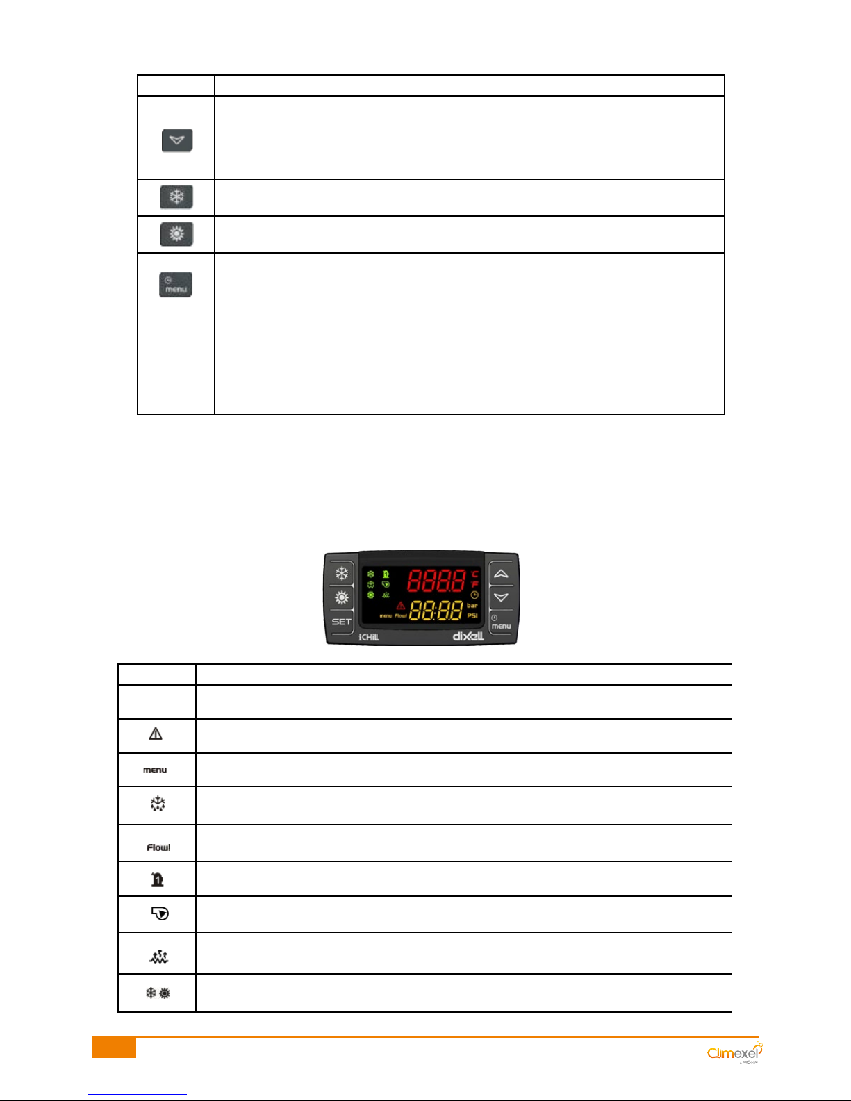
VI-2 Keypad functions
Key Function
Press and release:
Displays the chill set point (code SetC) or the heat set point (code SetH).
Press and hold down for 3 seconds:
Displays the chill or heat set point
Press and release in programming mode:
Allows access to parameter modification
Allows validation of new settings
Press and release:
Displays the sensor readings
Press and release in programming mode:
Scrolls through all parameters.
During modification, changes the value of a parameter.
36/96
2016/03 - Indice de révision : E - Code : 0033340
Key Function
Press and release:
Displays the sensor readings
Press and release in programming mode:
Scrolls through all parameters.
During modification, changes the value of a parameter.
Press and release:
Starts/ stops the machine in chill mode
Press and release:
Starts/ stops the machine in heat mode
Press and release:
Enters/exits the function menu, allows access to the following parameters:
- Eco / Confort mode
- Display and reset active alarms
- Parameter "Pout", displays the power level "Step"
- Activates / Deactivates the filtration slaving function "Ser" (option)
- Parameter "UPL" factory setting
- Parameter "ALOG" factory setting
Press and release in programming mode:
Returns to the previous programming mode level
VI-3 Display
Icon Definition
°C - °F
Appears when the temperature is displayed
Appears when an alarm is detected
Appears when the Menu key is pressed
Appears when defrosting is active
Appears when the water flow rate through the exchangeur is too low or absent
Appears when the compressor is running
Appears when filtration is slaved to the heat pump (optional)
Appears when defrost is activated while the temperature is less than 5°C (optional)
Appears when the machine is in heat or chill mode
 Loading...